EP4163533B1 - Elektromagnetisch betätigtes druckregelventil für ein aufblassystem - Google Patents
Elektromagnetisch betätigtes druckregelventil für ein aufblassystem Download PDFInfo
- Publication number
- EP4163533B1 EP4163533B1 EP22196114.7A EP22196114A EP4163533B1 EP 4163533 B1 EP4163533 B1 EP 4163533B1 EP 22196114 A EP22196114 A EP 22196114A EP 4163533 B1 EP4163533 B1 EP 4163533B1
- Authority
- EP
- European Patent Office
- Prior art keywords
- valve
- spool
- piston
- solenoid
- fluid
- Prior art date
- Legal status (The legal status is an assumption and is not a legal conclusion. Google has not performed a legal analysis and makes no representation as to the accuracy of the status listed.)
- Active
Links
Images



Classifications
-
- F—MECHANICAL ENGINEERING; LIGHTING; HEATING; WEAPONS; BLASTING
- F17—STORING OR DISTRIBUTING GASES OR LIQUIDS
- F17C—VESSELS FOR CONTAINING OR STORING COMPRESSED, LIQUEFIED OR SOLIDIFIED GASES; FIXED-CAPACITY GAS-HOLDERS; FILLING VESSELS WITH, OR DISCHARGING FROM VESSELS, COMPRESSED, LIQUEFIED, OR SOLIDIFIED GASES
- F17C7/00—Methods or apparatus for discharging liquefied, solidified, or compressed gases from pressure vessels, not covered by another subclass
-
- F—MECHANICAL ENGINEERING; LIGHTING; HEATING; WEAPONS; BLASTING
- F16—ENGINEERING ELEMENTS AND UNITS; GENERAL MEASURES FOR PRODUCING AND MAINTAINING EFFECTIVE FUNCTIONING OF MACHINES OR INSTALLATIONS; THERMAL INSULATION IN GENERAL
- F16K—VALVES; TAPS; COCKS; ACTUATING-FLOATS; DEVICES FOR VENTING OR AERATING
- F16K31/00—Actuating devices; Operating means; Releasing devices
- F16K31/003—Actuating devices; Operating means; Releasing devices operated without a stable intermediate position, e.g. with snap action
-
- F—MECHANICAL ENGINEERING; LIGHTING; HEATING; WEAPONS; BLASTING
- F16—ENGINEERING ELEMENTS AND UNITS; GENERAL MEASURES FOR PRODUCING AND MAINTAINING EFFECTIVE FUNCTIONING OF MACHINES OR INSTALLATIONS; THERMAL INSULATION IN GENERAL
- F16K—VALVES; TAPS; COCKS; ACTUATING-FLOATS; DEVICES FOR VENTING OR AERATING
- F16K31/00—Actuating devices; Operating means; Releasing devices
- F16K31/02—Actuating devices; Operating means; Releasing devices electric; magnetic
- F16K31/06—Actuating devices; Operating means; Releasing devices electric; magnetic using a magnet, e.g. diaphragm valves, cutting off by means of a liquid
- F16K31/0675—Electromagnet aspects, e.g. electric supply therefor
- F16K31/0679—Electromagnet aspects, e.g. electric supply therefor with more than one energising coil
-
- F—MECHANICAL ENGINEERING; LIGHTING; HEATING; WEAPONS; BLASTING
- F16—ENGINEERING ELEMENTS AND UNITS; GENERAL MEASURES FOR PRODUCING AND MAINTAINING EFFECTIVE FUNCTIONING OF MACHINES OR INSTALLATIONS; THERMAL INSULATION IN GENERAL
- F16K—VALVES; TAPS; COCKS; ACTUATING-FLOATS; DEVICES FOR VENTING OR AERATING
- F16K31/00—Actuating devices; Operating means; Releasing devices
- F16K31/12—Actuating devices; Operating means; Releasing devices actuated by fluid
- F16K31/122—Actuating devices; Operating means; Releasing devices actuated by fluid the fluid acting on a piston
- F16K31/1223—Actuating devices; Operating means; Releasing devices actuated by fluid the fluid acting on a piston one side of the piston being acted upon by the circulating fluid
-
- F—MECHANICAL ENGINEERING; LIGHTING; HEATING; WEAPONS; BLASTING
- F16—ENGINEERING ELEMENTS AND UNITS; GENERAL MEASURES FOR PRODUCING AND MAINTAINING EFFECTIVE FUNCTIONING OF MACHINES OR INSTALLATIONS; THERMAL INSULATION IN GENERAL
- F16K—VALVES; TAPS; COCKS; ACTUATING-FLOATS; DEVICES FOR VENTING OR AERATING
- F16K31/00—Actuating devices; Operating means; Releasing devices
- F16K31/12—Actuating devices; Operating means; Releasing devices actuated by fluid
- F16K31/122—Actuating devices; Operating means; Releasing devices actuated by fluid the fluid acting on a piston
- F16K31/124—Actuating devices; Operating means; Releasing devices actuated by fluid the fluid acting on a piston servo actuated
-
- F—MECHANICAL ENGINEERING; LIGHTING; HEATING; WEAPONS; BLASTING
- F17—STORING OR DISTRIBUTING GASES OR LIQUIDS
- F17C—VESSELS FOR CONTAINING OR STORING COMPRESSED, LIQUEFIED OR SOLIDIFIED GASES; FIXED-CAPACITY GAS-HOLDERS; FILLING VESSELS WITH, OR DISCHARGING FROM VESSELS, COMPRESSED, LIQUEFIED, OR SOLIDIFIED GASES
- F17C13/00—Details of vessels or of the filling or discharging of vessels
- F17C13/04—Arrangement or mounting of valves
-
- F—MECHANICAL ENGINEERING; LIGHTING; HEATING; WEAPONS; BLASTING
- F17—STORING OR DISTRIBUTING GASES OR LIQUIDS
- F17C—VESSELS FOR CONTAINING OR STORING COMPRESSED, LIQUEFIED OR SOLIDIFIED GASES; FIXED-CAPACITY GAS-HOLDERS; FILLING VESSELS WITH, OR DISCHARGING FROM VESSELS, COMPRESSED, LIQUEFIED, OR SOLIDIFIED GASES
- F17C2205/00—Vessel construction, in particular mounting arrangements, attachments or identifications means
- F17C2205/03—Fluid connections, filters, valves, closure means or other attachments
- F17C2205/0302—Fittings, valves, filters, or components in connection with the gas storage device
- F17C2205/0323—Valves
-
- F—MECHANICAL ENGINEERING; LIGHTING; HEATING; WEAPONS; BLASTING
- F17—STORING OR DISTRIBUTING GASES OR LIQUIDS
- F17C—VESSELS FOR CONTAINING OR STORING COMPRESSED, LIQUEFIED OR SOLIDIFIED GASES; FIXED-CAPACITY GAS-HOLDERS; FILLING VESSELS WITH, OR DISCHARGING FROM VESSELS, COMPRESSED, LIQUEFIED, OR SOLIDIFIED GASES
- F17C2205/00—Vessel construction, in particular mounting arrangements, attachments or identifications means
- F17C2205/03—Fluid connections, filters, valves, closure means or other attachments
- F17C2205/0302—Fittings, valves, filters, or components in connection with the gas storage device
- F17C2205/0323—Valves
- F17C2205/0326—Valves electrically actuated
-
- F—MECHANICAL ENGINEERING; LIGHTING; HEATING; WEAPONS; BLASTING
- F17—STORING OR DISTRIBUTING GASES OR LIQUIDS
- F17C—VESSELS FOR CONTAINING OR STORING COMPRESSED, LIQUEFIED OR SOLIDIFIED GASES; FIXED-CAPACITY GAS-HOLDERS; FILLING VESSELS WITH, OR DISCHARGING FROM VESSELS, COMPRESSED, LIQUEFIED, OR SOLIDIFIED GASES
- F17C2205/00—Vessel construction, in particular mounting arrangements, attachments or identifications means
- F17C2205/03—Fluid connections, filters, valves, closure means or other attachments
- F17C2205/0302—Fittings, valves, filters, or components in connection with the gas storage device
- F17C2205/0338—Pressure regulators
-
- F—MECHANICAL ENGINEERING; LIGHTING; HEATING; WEAPONS; BLASTING
- F17—STORING OR DISTRIBUTING GASES OR LIQUIDS
- F17C—VESSELS FOR CONTAINING OR STORING COMPRESSED, LIQUEFIED OR SOLIDIFIED GASES; FIXED-CAPACITY GAS-HOLDERS; FILLING VESSELS WITH, OR DISCHARGING FROM VESSELS, COMPRESSED, LIQUEFIED, OR SOLIDIFIED GASES
- F17C2205/00—Vessel construction, in particular mounting arrangements, attachments or identifications means
- F17C2205/03—Fluid connections, filters, valves, closure means or other attachments
- F17C2205/0388—Arrangement of valves, regulators, filters
- F17C2205/0394—Arrangement of valves, regulators, filters in direct contact with the pressure vessel
-
- F—MECHANICAL ENGINEERING; LIGHTING; HEATING; WEAPONS; BLASTING
- F17—STORING OR DISTRIBUTING GASES OR LIQUIDS
- F17C—VESSELS FOR CONTAINING OR STORING COMPRESSED, LIQUEFIED OR SOLIDIFIED GASES; FIXED-CAPACITY GAS-HOLDERS; FILLING VESSELS WITH, OR DISCHARGING FROM VESSELS, COMPRESSED, LIQUEFIED, OR SOLIDIFIED GASES
- F17C2225/00—Handled fluid after transfer, i.e. state of fluid after transfer from the vessel
- F17C2225/01—Handled fluid after transfer, i.e. state of fluid after transfer from the vessel characterised by the phase
- F17C2225/0107—Single phase
- F17C2225/0123—Single phase gaseous, e.g. CNG, GNC
-
- F—MECHANICAL ENGINEERING; LIGHTING; HEATING; WEAPONS; BLASTING
- F17—STORING OR DISTRIBUTING GASES OR LIQUIDS
- F17C—VESSELS FOR CONTAINING OR STORING COMPRESSED, LIQUEFIED OR SOLIDIFIED GASES; FIXED-CAPACITY GAS-HOLDERS; FILLING VESSELS WITH, OR DISCHARGING FROM VESSELS, COMPRESSED, LIQUEFIED, OR SOLIDIFIED GASES
- F17C2225/00—Handled fluid after transfer, i.e. state of fluid after transfer from the vessel
- F17C2225/03—Handled fluid after transfer, i.e. state of fluid after transfer from the vessel characterised by the pressure level
- F17C2225/036—Very high pressure, i.e. above 80 bars
-
- F—MECHANICAL ENGINEERING; LIGHTING; HEATING; WEAPONS; BLASTING
- F17—STORING OR DISTRIBUTING GASES OR LIQUIDS
- F17C—VESSELS FOR CONTAINING OR STORING COMPRESSED, LIQUEFIED OR SOLIDIFIED GASES; FIXED-CAPACITY GAS-HOLDERS; FILLING VESSELS WITH, OR DISCHARGING FROM VESSELS, COMPRESSED, LIQUEFIED, OR SOLIDIFIED GASES
- F17C2270/00—Applications
- F17C2270/01—Applications for fluid transport or storage
- F17C2270/0186—Applications for fluid transport or storage in the air or in space
- F17C2270/0189—Planes
-
- F—MECHANICAL ENGINEERING; LIGHTING; HEATING; WEAPONS; BLASTING
- F17—STORING OR DISTRIBUTING GASES OR LIQUIDS
- F17C—VESSELS FOR CONTAINING OR STORING COMPRESSED, LIQUEFIED OR SOLIDIFIED GASES; FIXED-CAPACITY GAS-HOLDERS; FILLING VESSELS WITH, OR DISCHARGING FROM VESSELS, COMPRESSED, LIQUEFIED, OR SOLIDIFIED GASES
- F17C2270/00—Applications
- F17C2270/07—Applications for household use
- F17C2270/0772—Inflation devices, e.g. for rescue vests or tyres
Definitions
- the present disclosure relates generally to inflatable fluid sources and, more particularly, to a valve arrangement for a pressurized fluid source of an evacuation assembly.
- Inflatable evacuation systems may be found on various structures, including aircraft, boats, offshore drilling platforms and the like.
- the systems are typically equipped with an inflatable or an inflatable device, such as, for example, an inflatable slide or an inflatable raft, configured to facilitate rapid evacuation of persons in the event of an emergency.
- inflatables are typically stored in an uninflated condition on the structure in a location readily accessible for deployment.
- an evacuation slide for a commercial aircraft is stored in an uninflated condition in a case or compartment located proximate an emergency exit.
- a valve arrangement for a pressurized fluid source is claimed as claimed in claim 1.
- the valve arrangement comprises a valve housing comprising an inlet, an outlet, and a main fluid channel extending along a longitudinal axis of the valve housing, a spool located in the main fluid channel, the spool configured to translate along the longitudinal axis of the valve housing, and a poppet valve located around the spool, the poppet valve configured to translate along the longitudinal axis of the valve housing.
- the spool comprises a first piston, a second piston, and a third piston.
- valve arrangement further comprises a first spring adjacent the first piston.
- the poppet valve is disposed between the first piston and the second piston.
- conduit 132 may be connected to a valve outlet 138 of a valve assembly 140 (also referred to herein as a pressure regulator shutoff valve or a solenoid operated pressure regulator cum shut off valve) fluidly coupled to pressurized fluid source 130.
- valve assembly 140 is fluidly coupled between pressurized fluid source 130 and conduit 132.
- valve assembly 140 is configured to regulate the flow of pressurized fluid from pressurized fluid source 130 to evacuation slide 120.
- evacuation slide 120 is in a stowed (or deflated) state
- valve assembly 140 is in a closed position.
- valve assembly 140 In response to deployment of evacuation assembly 106, valve assembly 140 translates to an open position, thereby allowing fluid to flow from pressurized fluid source 130 to evacuation slide 120.
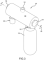
- valve assembly 140 includes a valve housing 150 (sometime referred to as a valve manifold).
- valve housing 150 may comprise an elongate cylindrical geometry extending along longitudinal axis 190.
- Valve housing 150 may be cylindrical shaped and provided with minimal numbers of internal flow passages.
- Valve housing 150 may be additively manufactured.
- Valve housing 150 may be manufactured using conventional machining methods. In this case, the internally provided flow passages may be drilled from the extreme side faces and the relevant openings plugged afterwards.
- Valve housing 150 may define valve outlet 138 and a valve inlet 152 of valve assembly 140.
- Valve assembly 140 receives fluid from pressurized fluid source 130 through valve inlet 152.
- a first cap 154 may form a fluid tight seal with valve housing 150.
- a second cap 156 may form a fluid tight seal with valve housing 150.
- First cap 154 may be disposed opposite valve housing 150 from second cap 156.
- first cap 154 and second cap 156 are coaxial with axis 190.
- Valve assembly 140 includes a solenoid initiator valve 200.
- Solenoid initiator valve 200 may be a dual solenoid valve. Solenoid initiator valve 200 may operate to place valve outlet 138 in fluid communication with valve inlet 152, as described herein.
- pressurized fluid source 130 may also be coupled to valve housing 150.
- a pressure gauge configured to measure a pressure of pressurized fluid source 130, may be operatively coupled to pressurized fluid source 130 via valve assembly 140.
- valve housing 150 may define valve inlet 152 and valve outlet 138 of valve assembly 140.
- Valve housing 150 may further define a main fluid channel 164 through valve housing 150.
- Main fluid channel 164 may be coaxial with longitudinal axis 190.
- Main fluid channel 164 may be fluidly connected with valve inlet 152 and valve outlet 138.
- a spool 165 is located in main fluid channel 164.
- spool 165 blocks, or otherwise prevents, the flow of pressurized fluid from pressurized fluid source 130 to valve outlet 138.
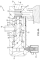
- a spring 201 biases the spool 165 in a first direction (i.e., to the left in FIG. 4A ) towards second cap 156 to secure spool 165 in the closed position.
- spring 201 biases the spool 165 to abut second cap 156 in the closed position.
- fluid pressure from pressurized fluid source 130 biases the spool 165 towards second cap 156 to secure spool 165 in the closed position.
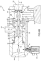
- fluid pressure from pressurized fluid source 130 and spring force from first spring 201 generates an interference with spool 165 that blocks spool 165 from translating in a second direction (i.e., to the right in FIG. 4B ) along longitudinal axis 190 toward cap 154-i.e., that blocks spool 165 from translating to/toward an open position.
- Spool 165 may comprise a spool stem 166.
- Spool stem 166 may comprise an elongate rod.
- Spool 165 may be coaxial with longitudinal axis 190.
- Spool 165 may comprise a piston 167 (also referred to herein as a first piston) extending from a first end (i.e., the right end of spool stem 166 in FIG. 4B ) of spool stem 166. Piston 167 may abut and seal against valve housing 150.
- Spool 165 may comprise a piston 168 (also referred to herein as a second piston) extending from a second end (i.e., the left end of spool stem 166 in FIG. 4B ) of spool stem 166.
- Piston 168 may abut and seal against a guide bushing 158.
- Spool 165 may comprise a piston 169 (also referred to herein as a third piston) extending from piston 168. Piston 169 may abut and seal against valve housing 150.
- Valve assembly 140 may further comprise the guide bushing 158 located in main fluid channel 164.
- Guide bushing 158 may be fixed to valve housing 150.
- Guide bushing 158 may be disposed between outlet 138 and second cap 156.
- Guide bushing 158 may be disposed between outlet 138 and solenoid initiator valve 200.
- Spool 165 may be disposed at least partially within guide bushing 158.
- Spool 165 may extend through guide bushing 158.
- Guide bushing 158 may guide translation of spool 165 along longitudinal axis 190 within main fluid channel 164.
- Valve assembly 140 may further comprise a poppet valve 160 (also referred to herein as a regulator valve) located in main fluid channel 164.
- Poppet valve 160 may be disposed at least partially within guide bushing 158.
- a first end of poppet valve 160 may extend into guide bushing 158.
- a second end of poppet valve 160 may abut a second spring 202 (also referred to herein as a regulator spring).
- Valve housing 150 may comprise a wall or flange 151 extending inward toward longitudinal axis 190 into main fluid channel 164.
- Regulator spring 202 may be disposed between flange 151 and poppet valve 160.
- Regulator spring 202 may abut flange 151.
- Regulator spring 202 may be disposed opposite flange 151 from piston 167.
- Guide bushing 158 may comprise a wall or flange 159 extending inward toward longitudinal axis 190 into main fluid channel 164.
- Poppet valve 160 may be disposed between flange 159 and regulator spring 202. Poppet valve 160 may abut flange 159.
- Regulator spring 202 may bias poppet valve 160 along longitudinal axis 190 in the first direction (i.e., to the left in FIG. 4A ) to/toward an open position.
- Poppet valve 160 may be disposed about spool 165. Stated differently, poppet valve 160 may surround a portion of spool stem 166. Spool 165 may extend through poppet valve 160. More specifically, spool stem 166 may extend through poppet valve 160. Spool 165 may extend through flange 159 and flange 151. More specifically, spool stem 166 may extend through flange 159 and flange 151. Spool 165, poppet valve 160, and guide bushing 158 may be coaxial with longitudinal axis 190. Spool 165 may guide translation of poppet valve 160 along longitudinal axis 190 within main fluid channel 164. Flange 151 may guide translation of spool 165 along longitudinal axis 190 within main fluid channel 164.
- Poppet valve 160 may comprise a piston 161 (also referred to herein as a first piston or a regulator piston). Poppet valve 160 may comprise a piston 162 (also referred to herein as a second piston or a regulator piston). Valve assembly 140 may further comprise a channel 136 (also referred to herein as a fluid feed channel) whereby valve outlet 138 is configured to receive a flow of pressurized fluid from valve inlet 152 in response to spool 165 moving to an open position. Channel 136 may be configured to feed the flow of pressurized fluid from valve inlet 152 to a location of main fluid channel 164 between piston 161 and piston 162. In the closed position, piston 167 may hermetically seal valve inlet 152 from channel 136 and valve outlet 138. Moreover, in the closed position, solenoid initiator valve 200 may hermetically seal valve inlet 152 from fluid communication with piston 169.
- Valve assembly 140 may further comprise a channel 134 (also referred to herein as a pilot feed channel) whereby a flow of pressurized fluid from pressurized fluid source 130 may be routed to solenoid initiator valve 200.
- Channel 134 may bypass main fluid channel 164 and route the flow of pressurized fluid directly to solenoid initiator valve 200.
- pressurized fluid 192 from pressurized fluid source 130 may flow through channel 134 into solenoid initiator valve 200, and from solenoid initiator valve 200 into main fluid channel 164.
- a force from said pressurized fluid 192 may act on piston 169 and overcome the bias of spring 201 to move spool 165 along longitudinal axis 190 toward first cap 154 with respect to valve housing 150.
- the spool 165 may begin to translate along longitudinal axis 190 in the second direction (i.e., to the right in FIG.
- the diameter of piston 169 may be greater than the diameter of piston 167 such that the surface area of piston 169 is greater than that of piston 167.
- the force of pressurized fluid 192 acting on piston 169 will be greater than the force of pressurized fluid acting on piston 167, even though the pressure of the pressurized fluid acting on both pistons 167, 169 may be the same.
- the pressurized fluid 193 applies a force (also referred to herein as a throttling down force) to piston 161 which tends to cause poppet valve 160 to translate in the second direction (i.e., to the right in FIG. 4B ) along longitudinal axis 190 against the bias of regulator spring 202.
- the pressurized fluid 193 also applies a force (also referred to herein as a throttling up force) to piston 162 which tends to cause poppet valve 160 to translate in the first direction (i.e., to the left in FIG. 4B ) along longitudinal axis 190, thereby providing more .
- Poppet valve 160 may occupy an intermediate position controlled by the force balancing between the above-mentioned opening and closing forces.
- Piston 161 may include a seal 163, such as a dynamic O-ring for example.
- the friction force of seal 163 may be considered as a resistance force to regulator opening when designing for force balancing of poppet valve 160.
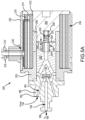
- Dual solenoid valve 200 is in the closed position.
- Dual solenoid valve 200 includes a core 203 and a bobbin 204.
- Core 203 may engage fluid fitting 186.
- Bobbin 204 may engage core fitting 206.
- Core fitting 206 is formed of a non-magnetic material.
- Core 203 and bobbin 204 are made of a magnetic material, such as a ferrous metal.
- a first (or inner) solenoid coil 210 is wrapped helically around core 203, bobbin 204, and core fitting 206.
- a first set of lead wires 212 e.g., a positive lead wire and a ground lead wire
- An insulating layer 214 is formed over an outer diameter of first solenoid coil 210. Stated differently, insulating layer 214 is radially outward of first solenoid coil 210.
- a second (or outer) solenoid coil 216 is wrapped helically around insulating layer 214.
- a second set of lead wires 218 is electrically coupled to second solenoid coil 216.
- Second solenoid coil 216 is radially outward of first solenoid coil 210 and insulating layer 214. Insulating layer 214 is located radially between second solenoid coil 216 and first solenoid coil 210.
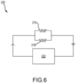
- first solenoid coil 210 and second solenoid coil 216 When both first solenoid coil 210 and second solenoid coil 216 are functioning and generating magnetic flux (i.e., when neither first solenoid coil 210 nor second solenoid coil 216 is broken or otherwise not generating magnetic flux), the current passing through each of first solenoid coil 210 and second solenoid coil 216 will be proportionate to the respective coil resistance values. In accordance with various embodiments, the magnetic field generated by first solenoid coil 210 and second solenoid coil 216 together will be additive.
- first solenoid coil 210 is equal to the solenoid resistance coil value of second solenoid coil 216
- the current passing through each of first solenoid coil 210 and second solenoid coil 216 is equal, or approximately equal, to one-half of the current output by power source 222.
- first solenoid coil 210 or second solenoid coil 216 fail (e.g., break or otherwise stop current flow through the solenoid coil)
- the total current output by power source 222 will pass through the fault-free solenoid coil.
- the total magnetic flux, or ampere-turns, generated by the dual solenoid valve 200 with momentary reference to FIG.
- first solenoid coil 210 and second solenoid coil 216 will be same when both first solenoid coil 210 and second solenoid coil 216 are working properly and when one of first solenoid coil 210 or second solenoid coil 216 is working properly and the other of first solenoid coil 210 and second solenoid coil 216 is faulty.
- a cover 230 may be located around second solenoid coil 216.
- Cover 230 may be coupled, via adhesive, welding, fasteners, or any other suitable attachment to bobbin 204 and/or to core 203.
- Cover 230 may define a lead wire opening 232 through which the first set of lead wires 212 and the second set of lead wires 218 are located.
- Cover 230, bobbin 204, core 203, and core fitting 206 define a cavity 234 in which first solenoid coil 210, insulating layer 214, and second solenoid coil 216 are located.
- Dual solenoid valve 200 further includes a plunger 240.
- Plunger 240 comprises a ferrous metal. Plunger 240 is configured such that plunger 240 will translate in the magnetic flux direction generated by first and second solenoid coils 210, 216. In this regard, the magnetic field generated by first and second solenoid coils 210, 216 forces plunger 240 away from fluid fitting 186.
- Valve seal 194 is coupled to plunger 240 such that valve seal 194 translates with plunger 240 relative to fluid fitting 186.
- Plunger 240 is biased toward fluid fitting 186.
- a coil spring 242 may bias plunger 240 toward fluid fitting 186.
- Coil spring 242 may be located between a spacer 244 of plunger 240 and a spacer 246 of bobbin 204.
- Spacer 244 may be located in a spacer cavity 248 defined by plunger 240.
- Spacer 246 may be located in spacer cavity 250 defined by bobbin 204.
- the biasing load generated by coil spring 242 may be applied to plunger 240 via spacer 244.
- spacer 244 comprises a non-magnetic material.
- the biasing load applied by coil spring 242 to plunger 240 creates a gap 252 between a surface 254 of plunger 240 and a surface 256 of bobbin 204.
- the biasing load applied by coil spring 242 to plunger 240 maintains a fluid tight seal between fluid fitting 186 and valve seal 194.
- dual solenoid valve 200 is illustrated in the open position.
- first solenoid coil 210 and/or second solenoid coil 216 In response to receiving a current via first set of lead wires 212 and/or second set of lead wires 218, first solenoid coil 210 and/or second solenoid coil 216 generate a magnetic field.
- current begins to flow to first solenoid coil 210 and/or second solenoid coil 216 in response to activation of power source 222.
- Power source 222 may be activated in response to deployment of evacuation assembly 106 ( FIG. 1 ). For example, opening exit door 104 ( FIG. 1 ) may activate power source 222 ( FIG.
- first solenoid coil 210 and/or close a circuit to electrically couple power source 222 to first and second solenoid coils 210, 216, and/or otherwise cause current to flow from power source 222 to first and second solenoid coils 210, 216.
- the electromagnetic force due to the magnetic flux value, or ampere-turns, generated by first solenoid coil 210 and/or by second solenoid coil 216 is greater than the biasing load applied by coil spring 242.
- the electromagnetic force being greater than the biasing load applied by coil spring 242, causes plunger 240 and valve seal 194 to translate away from fluid fitting 186, thereby creating a gap 260 between valve seal 194 and fluid fitting 186.
- the gap 260 between valve seal 194 and fluid fitting 186 fluidly connects inlet 182 and outlet 188 of fluid fitting 186, thereby allowably fluid from pressurized fluid source 130 to flow from channel 134 to the main fluid channel 164 at the location of piston 169.
- fluid from pressurized fluid source 130 may flow from valve inlet 152, through channel 134 in valve housing 150 and fluid path 184 in fluid fitting 186, and into the main fluid channel 164 at the location of piston 169.
- the increase in fluid volume in main fluid channel 164 at the location of piston 169 increases a pressure within main fluid channel 164 at the location of piston 169.
- spool 165 translates toward the open position in response to the pressure force acting on piston 169 exceeding the biasing force applied by spring 201 and the pressure force acting on piston 167.
- channel 136 is exposed to valve inlet 152.
- piston 167 moving from the closed position wherein piston 167 is located at a first side of valve inlet 152 (see FIG. 4A ) to an open position wherein piston 167 is located at a second side of valve inlet 152 (see FIG.
Landscapes
- Engineering & Computer Science (AREA)
- General Engineering & Computer Science (AREA)
- Mechanical Engineering (AREA)
- Physics & Mathematics (AREA)
- Electromagnetism (AREA)
- Magnetically Actuated Valves (AREA)
Claims (11)
- Ventilanordnung (140) für eine Druckfluidquelle (130), wobei die Ventilanordnung Folgendes umfasst:ein Ventilgehäuse (150), das einen Einlass (152), einen Auslass (138) und einen Hauptfluidkanal (164) umfasst, der sich entlang einer Längsachse (190) des Ventilgehäuses erstreckt;einen Schieber (165), der in dem Hauptfluidkanal liegt, wobei der Schieber dazu konfiguriert ist, sich entlang der Längsachse des Ventilgehäuses zu verschieben;ein Tellerventil (160), das um den Schieber herum liegt, wobei das Tellerventil dazu konfiguriert ist, sich entlang der Längsachse des Ventilgehäuses zu verschieben; undeinen Fluidzufuhrkanal (136), dadurch gekennzeichnet, dassder Fluidzufuhrkanal fluidisch von dem Einlass (152) des Ventilgehäuses getrennt ist, wenn sich der Schieber in einer geschlossenen Position befindet,der Fluidzufuhrkanal fluidisch mit dem Einlass des Ventilgehäuses verbunden ist, wenn sich der Schieber (165) in einer offenen Position befindet,der Auslass (138) durch den Fluidzufuhrkanal fluidisch mit dem Einlass des Ventilgehäuses verbunden ist, wenn sich der Schieber in der offenen Position befindet, unddas Tellerventil (160) einen Durchfluss eines Fluids von dem Einlass zu dem Auslass regelt, wenn sich der Schieber in der offenen Position befindet.
- Ventilanordnung nach Anspruch 1, wobei das Tellerventil (160) dazu konfiguriert ist, sich unabhängig von dem Schieber (165) entlang der Längsachse (190) des Ventilgehäuses zu verschieben.
- Ventilanordnung nach Anspruch 1 oder 2, wobei der Schieber (165) einen ersten Kolben (161), einen zweiten Kolben (162) und einen dritten Kolben (169) umfasst.
- Ventilanordnung nach Anspruch 3, ferner umfassend eine erste Feder (201) benachbart zu dem ersten Kolben (161).
- Ventilanordnung nach Anspruch 4, ferner umfassend eine zweite Feder (202) benachbart zu dem Tellerventil (160).
- Ventilanordnung nach einem der Ansprüche 3 bis 5, wobei das Tellerventil (160) zwischen dem ersten Kolben (161) und dem zweiten Kolben (162) angeordnet ist.
- Ventilanordnung nach Anspruch 6, wobei das Tellerventil (160) einen ersten Regelkolben und einen zweiten Regelkolben umfasst.
- Ventilanordnung nach Anspruch 6, ferner umfassend:ein Elektromagnetventil (200), das dazu konfiguriert ist, die Ventilanordnung zu öffnen und zu schließen; undeinen Pilotzufuhrkanal (134), durch den das Elektromagnetventil in Fluidverbindung mit dem Ventileinlass (152) steht.
- Evakuierungsbaugruppe (106), die Folgendes umfasst:eine Druckfluidquelle (130); unddie Ventilanordnung nach einem der vorhergehenden Ansprüche, wobei die Ventilanordnung dazu konfiguriert ist, einen Durchfluss von Druckfluid aus der Druckfluidquelle zu steuern.
- Evakuierungsbaugruppe nach Anspruch 9, ferner umfassend ein Doppel-Elektromagnetventil, das dazu konfiguriert ist, und die Ventilbaugruppe zu öffnen und zu schließen, wobei das Doppel-Elektromagnetventil eine erste Elektromagnetspule und eine zweite Elektromagnetspule beinhaltet, die parallel zur ersten Elektromagnetspule angeordnet ist.
- Evakuierungsbaugruppe nach Anspruch 9 oder 10, ferner umfassend einen Evakuierungsschieber (120), der fluidisch an den Ventilauslass gekoppelt ist.
Applications Claiming Priority (2)
| Application Number | Priority Date | Filing Date | Title |
|---|---|---|---|
| IN202141045668 | 2021-10-07 | ||
| US17/833,725 US11879562B2 (en) | 2021-10-07 | 2022-06-06 | Solenoid operated pressure regulator cum shut off valve for inflation system |
Publications (2)
| Publication Number | Publication Date |
|---|---|
| EP4163533A1 EP4163533A1 (de) | 2023-04-12 |
| EP4163533B1 true EP4163533B1 (de) | 2025-07-02 |
Family
ID=84044256
Family Applications (1)
| Application Number | Title | Priority Date | Filing Date |
|---|---|---|---|
| EP22196114.7A Active EP4163533B1 (de) | 2021-10-07 | 2022-09-16 | Elektromagnetisch betätigtes druckregelventil für ein aufblassystem |
Country Status (1)
| Country | Link |
|---|---|
| EP (1) | EP4163533B1 (de) |
Family Cites Families (6)
| Publication number | Priority date | Publication date | Assignee | Title |
|---|---|---|---|---|
| US3362424A (en) * | 1965-05-05 | 1968-01-09 | Vapor Corp | Fluid pressure regulating system |
| US20090250021A1 (en) * | 2007-10-02 | 2009-10-08 | Artificial Muscle, Inc. | Fluid control systems employing compliant electroactive materials |
| TWI780232B (zh) * | 2017-10-02 | 2022-10-11 | 美商沃辛頓工業股份有限公司 | 高壓減壓傾斜噴嘴 |
| US20190353263A1 (en) * | 2018-05-17 | 2019-11-21 | Goodrich Corporation | Poppet type pneumatic valve for inflation system |
| US10969034B2 (en) * | 2019-03-22 | 2021-04-06 | Goodrich Corporation | Inflation electric valve with manual override |
| US11119516B2 (en) * | 2019-12-11 | 2021-09-14 | Goodrich Coproration | Solenoid-operated pressure-regulator modules for inflation systems and methods thereof |
-
2022
- 2022-09-16 EP EP22196114.7A patent/EP4163533B1/de active Active
Also Published As
| Publication number | Publication date |
|---|---|
| EP4163533A1 (de) | 2023-04-12 |
Similar Documents
| Publication | Publication Date | Title |
|---|---|---|
| EP3835211B1 (de) | Elektromagnetisch betätigte module für aufblassysteme und deren montageverfahren | |
| KR100848059B1 (ko) | 공기 보조 복귀로가 마련된 직동형 공압 밸브 조립체 | |
| US11169552B2 (en) | Solenoid initiator with a manual override for inflation system | |
| US8656941B1 (en) | Flow control valve | |
| US11879562B2 (en) | Solenoid operated pressure regulator cum shut off valve for inflation system | |
| EP1463890B1 (de) | Vorgesteuertes druckluftventil | |
| US7401751B2 (en) | Fluid flow regulator with overpressure relief function | |
| US9404513B2 (en) | Servo valve | |
| US6540204B1 (en) | High pressure solenoid pilot valve | |
| CN114517856A (zh) | 高压直接先导致动的阀 | |
| US8359851B2 (en) | Trim actuator actuating system for a hydraulically actuatable trimmable horizontal stabilizer actuator | |
| EP4163533A1 (de) | Elektromagnetisch betätigtes druckregelventil für ein aufblassystem | |
| US20220196179A1 (en) | Dual solenoid initiator valve for compressed fluid sources | |
| WO2016175661A1 (en) | Dual parallel hydraulic actuator | |
| US20170241450A1 (en) | Proportional pressure controller with isolation valve assembly | |
| US12066847B2 (en) | Solenoid initiator for compressed fluid source regulator valve assembly | |
| EP4027050B1 (de) | Doppelmagnetinitiatorventil für druckfluidquellen | |
| EP4279781B1 (de) | Elektromagnetisch betätigter druckregler für ein aufblassystem | |
| US12085964B2 (en) | Smart pressure regulator for emergency evacuation inflation system | |
| US5623968A (en) | Valve assembly with manually actuated valve override | |
| US11802629B1 (en) | Solenoid actuated pressure regulator for inflation system | |
| EP4166452A1 (de) | Solenoidzünder für eine steuerventilanordnung einer druckmittelquelle | |
| US12297926B2 (en) | Solenoid operated pressure cartridge for inflation system | |
| EP4279389A1 (de) | Solenoidbetätigte druckpatrone für ein aufblassystem | |
| US11384850B2 (en) | Hydraulic control valves for ram air turbine stow actuators |
Legal Events
| Date | Code | Title | Description |
|---|---|---|---|
| PUAI | Public reference made under article 153(3) epc to a published international application that has entered the european phase |
Free format text: ORIGINAL CODE: 0009012 |
|
| STAA | Information on the status of an ep patent application or granted ep patent |
Free format text: STATUS: THE APPLICATION HAS BEEN PUBLISHED |
|
| AK | Designated contracting states |
Kind code of ref document: A1 Designated state(s): AL AT BE BG CH CY CZ DE DK EE ES FI FR GB GR HR HU IE IS IT LI LT LU LV MC MK MT NL NO PL PT RO RS SE SI SK SM TR |
|
| STAA | Information on the status of an ep patent application or granted ep patent |
Free format text: STATUS: REQUEST FOR EXAMINATION WAS MADE |
|
| P01 | Opt-out of the competence of the unified patent court (upc) registered |
Effective date: 20230922 |
|
| 17P | Request for examination filed |
Effective date: 20231006 |
|
| RBV | Designated contracting states (corrected) |
Designated state(s): AL AT BE BG CH CY CZ DE DK EE ES FI FR GB GR HR HU IE IS IT LI LT LU LV MC MK MT NL NO PL PT RO RS SE SI SK SM TR |
|
| GRAP | Despatch of communication of intention to grant a patent |
Free format text: ORIGINAL CODE: EPIDOSNIGR1 |
|
| STAA | Information on the status of an ep patent application or granted ep patent |
Free format text: STATUS: GRANT OF PATENT IS INTENDED |
|
| RIC1 | Information provided on ipc code assigned before grant |
Ipc: F17C 13/04 20060101ALI20250107BHEP Ipc: F17C 7/00 20060101AFI20250107BHEP |
|
| INTG | Intention to grant announced |
Effective date: 20250129 |
|
| GRAS | Grant fee paid |
Free format text: ORIGINAL CODE: EPIDOSNIGR3 |
|
| GRAA | (expected) grant |
Free format text: ORIGINAL CODE: 0009210 |
|
| STAA | Information on the status of an ep patent application or granted ep patent |
Free format text: STATUS: THE PATENT HAS BEEN GRANTED |
|
| AK | Designated contracting states |
Kind code of ref document: B1 Designated state(s): AL AT BE BG CH CY CZ DE DK EE ES FI FR GB GR HR HU IE IS IT LI LT LU LV MC MK MT NL NO PL PT RO RS SE SI SK SM TR |
|
| REG | Reference to a national code |
Ref country code: GB Ref legal event code: FG4D |
|
| REG | Reference to a national code |
Ref country code: CH Ref legal event code: EP |
|
| REG | Reference to a national code |
Ref country code: DE Ref legal event code: R096 Ref document number: 602022016770 Country of ref document: DE |
|
| REG | Reference to a national code |
Ref country code: IE Ref legal event code: FG4D |
|
| PGFP | Annual fee paid to national office [announced via postgrant information from national office to epo] |
Ref country code: DE Payment date: 20250820 Year of fee payment: 4 |
|
| PGFP | Annual fee paid to national office [announced via postgrant information from national office to epo] |
Ref country code: AT Payment date: 20251020 Year of fee payment: 4 Ref country code: FR Payment date: 20250821 Year of fee payment: 4 |
|
| REG | Reference to a national code |
Ref country code: NL Ref legal event code: MP Effective date: 20250702 |
|
| PG25 | Lapsed in a contracting state [announced via postgrant information from national office to epo] |
Ref country code: PT Free format text: LAPSE BECAUSE OF FAILURE TO SUBMIT A TRANSLATION OF THE DESCRIPTION OR TO PAY THE FEE WITHIN THE PRESCRIBED TIME-LIMIT Effective date: 20251103 |
|
| PG25 | Lapsed in a contracting state [announced via postgrant information from national office to epo] |
Ref country code: NL Free format text: LAPSE BECAUSE OF FAILURE TO SUBMIT A TRANSLATION OF THE DESCRIPTION OR TO PAY THE FEE WITHIN THE PRESCRIBED TIME-LIMIT Effective date: 20250702 |
|
| REG | Reference to a national code |
Ref country code: AT Ref legal event code: MK05 Ref document number: 1809578 Country of ref document: AT Kind code of ref document: T Effective date: 20250702 |
|
| PG25 | Lapsed in a contracting state [announced via postgrant information from national office to epo] |
Ref country code: IS Free format text: LAPSE BECAUSE OF FAILURE TO SUBMIT A TRANSLATION OF THE DESCRIPTION OR TO PAY THE FEE WITHIN THE PRESCRIBED TIME-LIMIT Effective date: 20251102 |
|
| PG25 | Lapsed in a contracting state [announced via postgrant information from national office to epo] |
Ref country code: NO Free format text: LAPSE BECAUSE OF FAILURE TO SUBMIT A TRANSLATION OF THE DESCRIPTION OR TO PAY THE FEE WITHIN THE PRESCRIBED TIME-LIMIT Effective date: 20251002 |
|
| REG | Reference to a national code |
Ref country code: LT Ref legal event code: MG9D |
|
| PG25 | Lapsed in a contracting state [announced via postgrant information from national office to epo] |
Ref country code: AT Free format text: LAPSE BECAUSE OF FAILURE TO SUBMIT A TRANSLATION OF THE DESCRIPTION OR TO PAY THE FEE WITHIN THE PRESCRIBED TIME-LIMIT Effective date: 20250702 |
|
| PG25 | Lapsed in a contracting state [announced via postgrant information from national office to epo] |
Ref country code: FI Free format text: LAPSE BECAUSE OF FAILURE TO SUBMIT A TRANSLATION OF THE DESCRIPTION OR TO PAY THE FEE WITHIN THE PRESCRIBED TIME-LIMIT Effective date: 20250702 |
|
| PG25 | Lapsed in a contracting state [announced via postgrant information from national office to epo] |
Ref country code: HR Free format text: LAPSE BECAUSE OF FAILURE TO SUBMIT A TRANSLATION OF THE DESCRIPTION OR TO PAY THE FEE WITHIN THE PRESCRIBED TIME-LIMIT Effective date: 20250702 |
|
| PG25 | Lapsed in a contracting state [announced via postgrant information from national office to epo] |
Ref country code: GR Free format text: LAPSE BECAUSE OF FAILURE TO SUBMIT A TRANSLATION OF THE DESCRIPTION OR TO PAY THE FEE WITHIN THE PRESCRIBED TIME-LIMIT Effective date: 20251003 |
|
| PG25 | Lapsed in a contracting state [announced via postgrant information from national office to epo] |
Ref country code: CZ Free format text: LAPSE BECAUSE OF FAILURE TO SUBMIT A TRANSLATION OF THE DESCRIPTION OR TO PAY THE FEE WITHIN THE PRESCRIBED TIME-LIMIT Effective date: 20250702 Ref country code: SE Free format text: LAPSE BECAUSE OF FAILURE TO SUBMIT A TRANSLATION OF THE DESCRIPTION OR TO PAY THE FEE WITHIN THE PRESCRIBED TIME-LIMIT Effective date: 20250702 |
|
| PG25 | Lapsed in a contracting state [announced via postgrant information from national office to epo] |
Ref country code: LV Free format text: LAPSE BECAUSE OF FAILURE TO SUBMIT A TRANSLATION OF THE DESCRIPTION OR TO PAY THE FEE WITHIN THE PRESCRIBED TIME-LIMIT Effective date: 20250702 |
|
| PG25 | Lapsed in a contracting state [announced via postgrant information from national office to epo] |
Ref country code: BG Free format text: LAPSE BECAUSE OF FAILURE TO SUBMIT A TRANSLATION OF THE DESCRIPTION OR TO PAY THE FEE WITHIN THE PRESCRIBED TIME-LIMIT Effective date: 20250702 Ref country code: PL Free format text: LAPSE BECAUSE OF FAILURE TO SUBMIT A TRANSLATION OF THE DESCRIPTION OR TO PAY THE FEE WITHIN THE PRESCRIBED TIME-LIMIT Effective date: 20250702 |
|
| PG25 | Lapsed in a contracting state [announced via postgrant information from national office to epo] |
Ref country code: RS Free format text: LAPSE BECAUSE OF FAILURE TO SUBMIT A TRANSLATION OF THE DESCRIPTION OR TO PAY THE FEE WITHIN THE PRESCRIBED TIME-LIMIT Effective date: 20251002 |
|
| PG25 | Lapsed in a contracting state [announced via postgrant information from national office to epo] |
Ref country code: ES Free format text: LAPSE BECAUSE OF FAILURE TO SUBMIT A TRANSLATION OF THE DESCRIPTION OR TO PAY THE FEE WITHIN THE PRESCRIBED TIME-LIMIT Effective date: 20250702 |
|
| PG25 | Lapsed in a contracting state [announced via postgrant information from national office to epo] |
Ref country code: RO Free format text: LAPSE BECAUSE OF FAILURE TO SUBMIT A TRANSLATION OF THE DESCRIPTION OR TO PAY THE FEE WITHIN THE PRESCRIBED TIME-LIMIT Effective date: 20250702 |
|
| PG25 | Lapsed in a contracting state [announced via postgrant information from national office to epo] |
Ref country code: SM Free format text: LAPSE BECAUSE OF FAILURE TO SUBMIT A TRANSLATION OF THE DESCRIPTION OR TO PAY THE FEE WITHIN THE PRESCRIBED TIME-LIMIT Effective date: 20250702 |
|
| REG | Reference to a national code |
Ref country code: DE Ref legal event code: R097 Ref document number: 602022016770 Country of ref document: DE |
|
| PG25 | Lapsed in a contracting state [announced via postgrant information from national office to epo] |
Ref country code: DK Free format text: LAPSE BECAUSE OF FAILURE TO SUBMIT A TRANSLATION OF THE DESCRIPTION OR TO PAY THE FEE WITHIN THE PRESCRIBED TIME-LIMIT Effective date: 20250702 |
|
| PG25 | Lapsed in a contracting state [announced via postgrant information from national office to epo] |
Ref country code: IT Free format text: LAPSE BECAUSE OF FAILURE TO SUBMIT A TRANSLATION OF THE DESCRIPTION OR TO PAY THE FEE WITHIN THE PRESCRIBED TIME-LIMIT Effective date: 20250702 |
|
| PG25 | Lapsed in a contracting state [announced via postgrant information from national office to epo] |
Ref country code: SK Free format text: LAPSE BECAUSE OF FAILURE TO SUBMIT A TRANSLATION OF THE DESCRIPTION OR TO PAY THE FEE WITHIN THE PRESCRIBED TIME-LIMIT Effective date: 20250702 Ref country code: EE Free format text: LAPSE BECAUSE OF FAILURE TO SUBMIT A TRANSLATION OF THE DESCRIPTION OR TO PAY THE FEE WITHIN THE PRESCRIBED TIME-LIMIT Effective date: 20250702 |
|
| REG | Reference to a national code |
Ref country code: CH Ref legal event code: H13 Free format text: ST27 STATUS EVENT CODE: U-0-0-H10-H13 (AS PROVIDED BY THE NATIONAL OFFICE) Effective date: 20260504 |
|
| PLBE | No opposition filed within time limit |
Free format text: ORIGINAL CODE: 0009261 |
|
| STAA | Information on the status of an ep patent application or granted ep patent |
Free format text: STATUS: NO OPPOSITION FILED WITHIN TIME LIMIT |
|
| PG25 | Lapsed in a contracting state [announced via postgrant information from national office to epo] |
Ref country code: LU Free format text: LAPSE BECAUSE OF NON-PAYMENT OF DUE FEES Effective date: 20250916 |
|
| REG | Reference to a national code |
Ref country code: CH Ref legal event code: L10 Free format text: ST27 STATUS EVENT CODE: U-0-0-L10-L00 (AS PROVIDED BY THE NATIONAL OFFICE) Effective date: 20260518 |
|
| REG | Reference to a national code |
Ref country code: BE Ref legal event code: MM Effective date: 20250930 |
|
| 26N | No opposition filed |
Effective date: 20260407 |
|
| PG25 | Lapsed in a contracting state [announced via postgrant information from national office to epo] |
Ref country code: LT Free format text: LAPSE BECAUSE OF FAILURE TO SUBMIT A TRANSLATION OF THE DESCRIPTION OR TO PAY THE FEE WITHIN THE PRESCRIBED TIME-LIMIT Effective date: 20250702 Ref country code: MC Free format text: LAPSE BECAUSE OF FAILURE TO SUBMIT A TRANSLATION OF THE DESCRIPTION OR TO PAY THE FEE WITHIN THE PRESCRIBED TIME-LIMIT Effective date: 20250702 |
|
| PG25 | Lapsed in a contracting state [announced via postgrant information from national office to epo] |
Ref country code: CH Free format text: LAPSE BECAUSE OF NON-PAYMENT OF DUE FEES Effective date: 20250930 Ref country code: BE Free format text: LAPSE BECAUSE OF NON-PAYMENT OF DUE FEES Effective date: 20250930 Ref country code: IE Free format text: LAPSE BECAUSE OF NON-PAYMENT OF DUE FEES Effective date: 20250916 |