EP4163548A2 - Materialabscheidung für fluidinjektoren - Google Patents
Materialabscheidung für fluidinjektoren Download PDFInfo
- Publication number
- EP4163548A2 EP4163548A2 EP22199618.4A EP22199618A EP4163548A2 EP 4163548 A2 EP4163548 A2 EP 4163548A2 EP 22199618 A EP22199618 A EP 22199618A EP 4163548 A2 EP4163548 A2 EP 4163548A2
- Authority
- EP
- European Patent Office
- Prior art keywords
- piece
- braze
- prefilmer
- fluid injector
- tube stock
- Prior art date
- Legal status (The legal status is an assumption and is not a legal conclusion. Google has not performed a legal analysis and makes no representation as to the accuracy of the status listed.)
- Granted
Links
Images



Classifications
-
- B—PERFORMING OPERATIONS; TRANSPORTING
- B23—MACHINE TOOLS; METAL-WORKING NOT OTHERWISE PROVIDED FOR
- B23K—SOLDERING OR UNSOLDERING; WELDING; CLADDING OR PLATING BY SOLDERING OR WELDING; CUTTING BY APPLYING HEAT LOCALLY, e.g. FLAME CUTTING; WORKING BY LASER BEAM
- B23K1/00—Soldering, e.g. brazing, or unsoldering
- B23K1/0008—Soldering, e.g. brazing, or unsoldering specially adapted for particular articles or work
- B23K1/0018—Brazing of turbine parts
-
- F—MECHANICAL ENGINEERING; LIGHTING; HEATING; WEAPONS; BLASTING
- F23—COMBUSTION APPARATUS; COMBUSTION PROCESSES
- F23R—GENERATING COMBUSTION PRODUCTS OF HIGH PRESSURE OR HIGH VELOCITY, e.g. GAS-TURBINE COMBUSTION CHAMBERS
- F23R3/00—Continuous combustion chambers using liquid or gaseous fuel
- F23R3/28—Continuous combustion chambers using liquid or gaseous fuel characterised by the fuel supply
-
- B—PERFORMING OPERATIONS; TRANSPORTING
- B23—MACHINE TOOLS; METAL-WORKING NOT OTHERWISE PROVIDED FOR
- B23K—SOLDERING OR UNSOLDERING; WELDING; CLADDING OR PLATING BY SOLDERING OR WELDING; CUTTING BY APPLYING HEAT LOCALLY, e.g. FLAME CUTTING; WORKING BY LASER BEAM
- B23K26/00—Working by laser beam, e.g. welding, cutting or boring
- B23K26/34—Laser welding for purposes other than joining
- B23K26/342—Build-up welding
-
- F—MECHANICAL ENGINEERING; LIGHTING; HEATING; WEAPONS; BLASTING
- F02—COMBUSTION ENGINES; HOT-GAS OR COMBUSTION-PRODUCT ENGINE PLANTS
- F02M—SUPPLYING COMBUSTION ENGINES IN GENERAL WITH COMBUSTIBLE MIXTURES OR CONSTITUENTS THEREOF
- F02M61/00—Fuel-injectors not provided for in groups F02M39/00 - F02M57/00 or F02M67/00
- F02M61/16—Details not provided for in, or of interest apart from, the apparatus of groups F02M61/02 - F02M61/14
- F02M61/168—Assembling; Disassembling; Manufacturing; Adjusting
-
- F—MECHANICAL ENGINEERING; LIGHTING; HEATING; WEAPONS; BLASTING
- F23—COMBUSTION APPARATUS; COMBUSTION PROCESSES
- F23R—GENERATING COMBUSTION PRODUCTS OF HIGH PRESSURE OR HIGH VELOCITY, e.g. GAS-TURBINE COMBUSTION CHAMBERS
- F23R3/00—Continuous combustion chambers using liquid or gaseous fuel
- F23R3/02—Continuous combustion chambers using liquid or gaseous fuel characterised by the air-flow or gas-flow configuration
- F23R3/04—Air inlet arrangements
- F23R3/10—Air inlet arrangements for primary air
- F23R3/12—Air inlet arrangements for primary air inducing a vortex
- F23R3/14—Air inlet arrangements for primary air inducing a vortex by using swirl vanes
-
- B—PERFORMING OPERATIONS; TRANSPORTING
- B23—MACHINE TOOLS; METAL-WORKING NOT OTHERWISE PROVIDED FOR
- B23K—SOLDERING OR UNSOLDERING; WELDING; CLADDING OR PLATING BY SOLDERING OR WELDING; CUTTING BY APPLYING HEAT LOCALLY, e.g. FLAME CUTTING; WORKING BY LASER BEAM
- B23K2101/00—Articles made by soldering, welding or cutting
- B23K2101/001—Turbines
-
- B—PERFORMING OPERATIONS; TRANSPORTING
- B23—MACHINE TOOLS; METAL-WORKING NOT OTHERWISE PROVIDED FOR
- B23K—SOLDERING OR UNSOLDERING; WELDING; CLADDING OR PLATING BY SOLDERING OR WELDING; CUTTING BY APPLYING HEAT LOCALLY, e.g. FLAME CUTTING; WORKING BY LASER BEAM
- B23K26/00—Working by laser beam, e.g. welding, cutting or boring
- B23K26/0093—Working by laser beam, e.g. welding, cutting or boring combined with mechanical machining or metal-working covered by other subclasses than B23K
-
- B—PERFORMING OPERATIONS; TRANSPORTING
- B23—MACHINE TOOLS; METAL-WORKING NOT OTHERWISE PROVIDED FOR
- B23P—METAL-WORKING NOT OTHERWISE PROVIDED FOR; COMBINED OPERATIONS; UNIVERSAL MACHINE TOOLS
- B23P15/00—Making specific metal objects by operations not covered by a single other subclass or a group in this subclass
-
- B—PERFORMING OPERATIONS; TRANSPORTING
- B23—MACHINE TOOLS; METAL-WORKING NOT OTHERWISE PROVIDED FOR
- B23P—METAL-WORKING NOT OTHERWISE PROVIDED FOR; COMBINED OPERATIONS; UNIVERSAL MACHINE TOOLS
- B23P2700/00—Indexing scheme relating to the articles being treated, e.g. manufactured, repaired, assembled, connected or other operations covered in the subgroups
- B23P2700/13—Parts of turbine combustion chambers
-
- F—MECHANICAL ENGINEERING; LIGHTING; HEATING; WEAPONS; BLASTING
- F02—COMBUSTION ENGINES; HOT-GAS OR COMBUSTION-PRODUCT ENGINE PLANTS
- F02M—SUPPLYING COMBUSTION ENGINES IN GENERAL WITH COMBUSTIBLE MIXTURES OR CONSTITUENTS THEREOF
- F02M2200/00—Details of fuel-injection apparatus, not otherwise provided for
- F02M2200/80—Fuel injection apparatus manufacture, repair or assembly
-
- F—MECHANICAL ENGINEERING; LIGHTING; HEATING; WEAPONS; BLASTING
- F02—COMBUSTION ENGINES; HOT-GAS OR COMBUSTION-PRODUCT ENGINE PLANTS
- F02M—SUPPLYING COMBUSTION ENGINES IN GENERAL WITH COMBUSTIBLE MIXTURES OR CONSTITUENTS THEREOF
- F02M2200/00—Details of fuel-injection apparatus, not otherwise provided for
- F02M2200/80—Fuel injection apparatus manufacture, repair or assembly
- F02M2200/8069—Fuel injection apparatus manufacture, repair or assembly involving removal of material from the fuel apparatus, e.g. by punching, hydro-erosion or mechanical operation
-
- F—MECHANICAL ENGINEERING; LIGHTING; HEATING; WEAPONS; BLASTING
- F02—COMBUSTION ENGINES; HOT-GAS OR COMBUSTION-PRODUCT ENGINE PLANTS
- F02M—SUPPLYING COMBUSTION ENGINES IN GENERAL WITH COMBUSTIBLE MIXTURES OR CONSTITUENTS THEREOF
- F02M2200/00—Details of fuel-injection apparatus, not otherwise provided for
- F02M2200/80—Fuel injection apparatus manufacture, repair or assembly
- F02M2200/8084—Fuel injection apparatus manufacture, repair or assembly involving welding or soldering
-
- F—MECHANICAL ENGINEERING; LIGHTING; HEATING; WEAPONS; BLASTING
- F23—COMBUSTION APPARATUS; COMBUSTION PROCESSES
- F23D—BURNERS
- F23D2900/00—Special features of, or arrangements for burners using fluid fuels or solid fuels suspended in a carrier gas
- F23D2900/11101—Pulverising gas flow impinging on fuel from pre-filming surface, e.g. lip atomizers
-
- F—MECHANICAL ENGINEERING; LIGHTING; HEATING; WEAPONS; BLASTING
- F23—COMBUSTION APPARATUS; COMBUSTION PROCESSES
- F23R—GENERATING COMBUSTION PRODUCTS OF HIGH PRESSURE OR HIGH VELOCITY, e.g. GAS-TURBINE COMBUSTION CHAMBERS
- F23R2900/00—Special features of, or arrangements for continuous combustion chambers; Combustion processes therefor
- F23R2900/00018—Manufacturing combustion chamber liners or subparts
-
- F—MECHANICAL ENGINEERING; LIGHTING; HEATING; WEAPONS; BLASTING
- F23—COMBUSTION APPARATUS; COMBUSTION PROCESSES
- F23R—GENERATING COMBUSTION PRODUCTS OF HIGH PRESSURE OR HIGH VELOCITY, e.g. GAS-TURBINE COMBUSTION CHAMBERS
- F23R3/00—Continuous combustion chambers using liquid or gaseous fuel
- F23R3/28—Continuous combustion chambers using liquid or gaseous fuel characterised by the fuel supply
- F23R3/30—Continuous combustion chambers using liquid or gaseous fuel characterised by the fuel supply comprising fuel prevapourising devices
- F23R3/32—Continuous combustion chambers using liquid or gaseous fuel characterised by the fuel supply comprising fuel prevapourising devices being tubular
Definitions
- the present disclosure relates to fluid injectors, and more particularly to fluid injectors for gas turbine engines.
- the fuel circuit In pure air-blast fuel injectors, the fuel circuit must be attached to the fuel tube. In order to have a suitable braze length, the fuel prefilmer component must often be made from a large single piece of material and then a large percentage of the material must be removed through machining.
- the fuel circuit in an air-blast injector requires a good surface for the liquid to film across. In many applications, this surface extends conically inwards along the interior of a prefilmer. In the usual method of manufacturing prefilmers, a piece of bar stock is often turned down to form this final surface.
- the fuel distributer requires features like spin slots which are usually machined into this component. There are often braze joint surfaces which connect to the prefilmer component or other components. In the usual method of manufacturing fuel distributers, a piece of bar stock is often turned down to a final surface.
- outer air swirlers In pure air-blast fuel injectors and pressure atomizer fuel injectors, there are often integral outer air swirlers. These components often require a slender, tube-like portion which acts as a heat shield along the fuel distributer, but also larger diameter material for the air swirler component.
- the outer air swirler is often made from a large piece of material stock and turned down to its final shape.
- a method of making a fluid injector for a gas turbine engine includes depositing material onto a piece of tube stock. The method includes machining the deposited material into a fluid injector component.
- Depositing can include laser cladding, electron beam cladding, cold spaying, and/or plasma spraying the material onto the piece of tube stock.
- the piece of tube stock can be a prefilmer.
- Depositing material can include depositing material on only a portion of a circumference of an outer surface of the piece of tube stock. Machining can include forming a joint surface into the deposited material.
- the method can include forming a passage through the deposited material and through the piece of tube stock to form a passage through the added material and into an interior of the piece of tube stock.
- the method can include placing or flowing braze into a braze joint location between the deposited material and a fluid injector feed arm and forming the braze into a braze joint in the braze joint location to join the feed arm to the prefilmer.
- Depositing material can include depositing material on an axial end of the piece of tube stock around a full circumference of the axial end. Machining can include forming a prefilming surface on an inside portion of the deposited material. Machining can include forming the deposited material into a frustoconical surface that converges in a direction away from the piece of tube stock material.
- Depositing material can include depositing material about a full circumference of an outer surface of the piece of tube stock at one axial end of the piece of tube stock. Machining can include forming the deposited material into an outer air swirler. Machining can include forming air passages through the deposited material. Machining can include forming an outer air cap outboard of air passages in the deposited material. Machining can include forming a braze surface in the deposited material and brazing an outer air cap and/or fluid distributor to the braze surface.
- the piece of tube stock can be a fluid distributor.
- Depositing material can include depositing a raised feature extending fully circumferentially around the piece of tube stock. Machining can include forming fluid slots in the raised feature. Machining can include forming a braze joint surface on an outward facing aspect of the raised feature.
- the method can include placing or flowing braze into a braze joint location between the braze joint surface and an inner surface of a prefilmer and forming the braze into a braze joint in the braze joint location to join the fluid distributor to the prefilmer.
- a fluid injector includes a first fluid injector component, a second fluid injector component, and a metallurgical joint joining the first fluid injector component to the second fluid injector component.
- the metallurgical joint includes a metallurgical crystal structure having a first crystal structure boundary between the first fluid injector component and a deposited material, a second crystal structure boundary between the deposited material and a braze material, and a third crystal structure boundary between the braze material and the second fluid injector component.
- the first fluid injector component can include a prefilmer and the second fluid injector component includes a feed arm.
- the first fluid injector component can include a fluid distributor and the second fluid injector component includes a prefilmer.
- the first fluid injector component can include a prefilmer and the second fluid injector component includes an outer air cap.
- FIG. 1 a partial view of an embodiment of a fluid injector in accordance with the disclosure is shown in Fig. 1 and is designated generally by reference character 100.
- FIGs. 2-16 Other embodiments of systems in accordance with the disclosure, or aspects thereof, are provided in Figs. 2-16 , as will be described.
- the systems and methods described herein can be used to construct fluid injectors such as used in gas turbine engines.
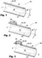
- a method of making a fluid injector 100 includes starting with a piece of tube stock 102 as shown in Fig. 1 , then depositing material 104 onto a piece of tube stock 102, as shown in Fig. 2 .
- the material 104 can be deposited using laser cladding, which in the case of Figs. 1-3 only includes depositing the material 104 on a portion of the circumference C of the outer surface 110 of the piece of tube stock 102. While laser cladding is discussed herein, those skilled in the art will readily appreciate that any other suitable deposition process can be used such as (but not limited to) electron beam cladding, cold spaying, or plasma spraying.
- the method includes machining the deposited material 104 into a fluid injector component 106, as shown in Fig. 3 .
- the piece of tube stock 102 is a prefilmer 103, and the injector component 106 includes a joint surface 108, which is machined into the material 104.
- a passage 112 is formed, e.g. by machining, through the deposited material 104 and through the piece of tube stock 102 into an interior 114 of the piece of tube stock 102.
- the method includes placing or flowing braze into a braze joint location 116 between the deposited material 104 and a feed arm 118 of the fluid injector 100.
- the braze joint is formed in the braze joint location 116 when the braze is cooled to join the feed arm 118 to the prefilmer 103.
- the feed arm could instead be fitted over and joined to an outward facing surface of the deposited material 104.
- any other suitable joining technique besides brazing can be used, such as welding.
- a piece of tube stock 102 as shown in Fig. 5 can be formed into a prefilmer 103 as shown in Fig. 7 .
- the method includes depositing material 120 using laser cladding on an axial end 122 of the piece of tube stock around a full circumference C of the axial end 122, relative to the central axis A of the piece of tube stock 102.
- a frustoconical prefilming surface 124 is formed on an inside portion of the deposited material 120 by machining.
- the frustoconical prefilming surface 124 converges in a direction away from the piece of tube stock material 102 so that fluid such as liquid fuel, gas fuel, air, or the like flowing through the prefilmer 103 flows into the surface 124 and forms a converting film of fluid flow, e.g. for air blast atomization.
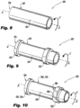
- a fluid distributor 126 as shown in Fig. 10 can be formed starting from a piece of tube stock 128 shown in Fig. 8 .
- two raised features 130, 132 of material are deposited by laser cladding about the full circumference of C of an outer surface 134 of the piece of tube stock 128.
- the method includes machining the deposited material of the first raised feature 130 to form a braze joint surface 136 on an outward facing aspect of the raised feature 130, as indicated in Fig. 10 .
- Fig. 9 two raised features 130, 132 of material are deposited by laser cladding about the full circumference of C of an outer surface 134 of the piece of tube stock 128.
- the method includes machining the deposited material of the first raised feature 130 to form a braze joint surface 136 on an outward facing aspect of the raised feature 130, as indicated in Fig. 10 .
- Fig. 10 As also shown in Fig.
- machining includes forming fluid slots 138 in the raised feature 132, which can also optionally have its outer surface machine into a braze joint surface 140, or be machined to the final diameter needed for a tight press fit or interference fit to form a good sealing surface with a mating surface located outboard of the surface 140 (i.e. prefilmer 103 of Fig. 7 ).
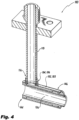
- the method includes placing or flowing braze into respective braze joint locations 144, 146 (identified in Fig. 4 ) between the braze joint surfaces 136, 140 and an inner surface 142 of a prefilmer 103 (labeled in Figs. 1-3 ) and forming the braze into a braze joint in the braze joint locations 144, 146 to join the fluid distributor 126 to the prefilmer 103 as shown in Fig. 4 .
- an outer air swirler 148 can be formed on a heat shield 105 as shown in Fig. 13 .
- the first raised feature 150 is deposited at or proximate the axial end 122 of the piece of tube stock 102. Machining includes forming the deposited material of the raised feature 150 into an outer air swirler 148 as shown in Fig. 13 . This can include forming air passages 152 through the deposited material 150.
- an outer air cap 154 is machined outboard of air passages 152.
- Fig. 12 the first raised feature 150 is deposited at or proximate the axial end 122 of the piece of tube stock 102. Machining includes forming the deposited material of the raised feature 150 into an outer air swirler 148 as shown in Fig. 13 . This can include forming air passages 152 through the deposited material 150.
- an outer air cap 154 is machined outboard of air passages 152.
- air passages 152 can be machined out of the deposited material, leaving vanes 158 between the air passages 152.
- Braze surfaces 156 are machined on the outward facing surfaces of vanes 158.
- An outer air cap 154 can be brazed to the braze surfaces 156.
- the fluid injector 100 includes a prefilmer 103 having an outer air swirler 148 (on the heat shield 105) and prefilming surface 124 formed thereon, with the feed arm 118 and fluid distributor 126 brazed in place as shown and described above.
- a prefilmer 103 having an outer air swirler 148 (on the heat shield 105) and prefilming surface 124 formed thereon, with the feed arm 118 and fluid distributor 126 brazed in place as shown and described above.
- additional fluid injector components can be added to the fluid injector 100 of Fig. 15 , such as heat shields, inlet fittings, strainers, inner air swirlers without departing from the scope of this disclosure.
- each braze joints are formed where the feed arm 118 is brazed to the prefilmer 103, where the fluid distributor 126 is brazed to the prefilmer 103, and optionally where an outer air cap 154 is brazed to vanes 158 as shown in Fig. 14 , a metallurgical joint 160 is formed.
- the metallurgical crystal structure of the joint 160 includes a first crystal structure boundary 162 between the first fluid injector component 164 (e.g. prefilmer 103, fluid distributor 126, or vanes 158) and a laser clad material 166.
- a second crystal structure boundary 168 is between the laser clad material 166 and a braze material 170 (e.g.
- a third crystal structure boundary 172 is between the braze material 170 and the second fluid injector component 174 (e.g. feed arm 118, prefilmer 103, or air cap 154).
- the second fluid injector component 174 e.g. feed arm 118, prefilmer 103, or air cap 154.
- Processes as disclosed herein allow for inexpensive tube materials to be used with more expensive materials such as high temperature materials for the air swirler side of the component, or very hard materials for the wear surfaces which interact with burner seals, for example.
- An additional potential advantage is that inexpensive material can be used for the tube body while specialized materials can be clad onto it.
- a high temperature material can be used for the tip of the injector 100.
Landscapes
- Engineering & Computer Science (AREA)
- Mechanical Engineering (AREA)
- Chemical & Material Sciences (AREA)
- Combustion & Propulsion (AREA)
- General Engineering & Computer Science (AREA)
- Physics & Mathematics (AREA)
- Optics & Photonics (AREA)
- Plasma & Fusion (AREA)
- Manufacturing & Machinery (AREA)
- Laser Beam Processing (AREA)
- Fuel-Injection Apparatus (AREA)
- Chemical Vapour Deposition (AREA)
Applications Claiming Priority (1)
| Application Number | Priority Date | Filing Date | Title |
|---|---|---|---|
| US17/494,544 US11701726B2 (en) | 2021-10-05 | 2021-10-05 | Material deposition for fluid injectors |
Publications (3)
| Publication Number | Publication Date |
|---|---|
| EP4163548A2 true EP4163548A2 (de) | 2023-04-12 |
| EP4163548A3 EP4163548A3 (de) | 2023-06-21 |
| EP4163548B1 EP4163548B1 (de) | 2025-11-26 |
Family
ID=83594241
Family Applications (1)
| Application Number | Title | Priority Date | Filing Date |
|---|---|---|---|
| EP22199618.4A Active EP4163548B1 (de) | 2021-10-05 | 2022-10-04 | Verfahren zur herstellung eines fluidinjektors |
Country Status (2)
| Country | Link |
|---|---|
| US (2) | US11701726B2 (de) |
| EP (1) | EP4163548B1 (de) |
Family Cites Families (12)
| Publication number | Priority date | Publication date | Assignee | Title |
|---|---|---|---|---|
| US6622488B2 (en) * | 2001-03-21 | 2003-09-23 | Parker-Hannifin Corporation | Pure airblast nozzle |
| US7506510B2 (en) | 2006-01-17 | 2009-03-24 | Delavan Inc | System and method for cooling a staged airblast fuel injector |
| DE102007050276A1 (de) | 2007-10-18 | 2009-04-23 | Rolls-Royce Deutschland Ltd & Co Kg | Magervormischbrenner für ein Gasturbinentriebwerk |
| US9228498B2 (en) * | 2012-03-01 | 2016-01-05 | Solar Turbines Incorporated | Laser clad fuel injector premix barrel |
| US9310081B2 (en) * | 2012-05-14 | 2016-04-12 | Delavan Inc. | Methods of fabricating fuel injectors using laser additive deposition |
| GB201315008D0 (en) | 2013-08-22 | 2013-10-02 | Rolls Royce Plc | Airblast fuel injector |
| US9657899B2 (en) | 2013-08-26 | 2017-05-23 | General Electric Company | Replacement oil cartridge tip and method |
| US20160361766A1 (en) * | 2013-12-20 | 2016-12-15 | Sandvik Intellectual Property Ab | Method for manufacturing a fuel nozzle blank with a metallic cladding |
| US20160325369A1 (en) | 2015-05-05 | 2016-11-10 | Delavan Inc | Braze cladding |
| US11261757B2 (en) | 2019-12-05 | 2022-03-01 | Pratt & Whitney Canada Corp. | Boss for gas turbine engine |
| CN112663051B (zh) | 2020-12-18 | 2022-11-04 | 国营四达机械制造公司 | 一种飞机起落架轮轴外螺纹局部损伤激光熔覆修复方法 |
| JP7636227B2 (ja) * | 2021-03-26 | 2025-02-26 | 本田技研工業株式会社 | ガスタービン用燃料ノズル装置 |
-
2021
- 2021-10-05 US US17/494,544 patent/US11701726B2/en active Active
-
2022
- 2022-10-04 EP EP22199618.4A patent/EP4163548B1/de active Active
-
2023
- 2023-02-23 US US18/113,286 patent/US12157178B2/en active Active
Also Published As
| Publication number | Publication date |
|---|---|
| US12157178B2 (en) | 2024-12-03 |
| US20230201943A1 (en) | 2023-06-29 |
| EP4163548B1 (de) | 2025-11-26 |
| EP4163548A3 (de) | 2023-06-21 |
| US11701726B2 (en) | 2023-07-18 |
| US20230105416A1 (en) | 2023-04-06 |
Similar Documents
| Publication | Publication Date | Title |
|---|---|---|
| US5423178A (en) | Multiple passage cooling circuit method and device for gas turbine engine fuel nozzle | |
| US7926178B2 (en) | Method of fuel nozzle construction | |
| US10488047B2 (en) | Thermally compliant additively manufactured fuel injector | |
| US5761907A (en) | Thermal gradient dispersing heatshield assembly | |
| US9989259B2 (en) | Laser clad fuel injector premix barrel | |
| CN102162398A (zh) | 控制燃气轮机的燃烧器的方法 | |
| US7513116B2 (en) | Gas turbine engine fuel injector having a fuel swirler | |
| EP4163548B1 (de) | Verfahren zur herstellung eines fluidinjektors | |
| CN102162640A (zh) | 燃料喷射器喷嘴 | |
| EP4339515B1 (de) | Brennstoffdüse | |
| EP4163550B1 (de) | Materialbeschichtung für fluiddüsenverbindungen | |
| EP4703644A1 (de) | Mittels generativer fertigung hergestellte monolithische brennstoffdüsenanordnung | |
| JP2005321157A (ja) | 燃焼器ノズル構造 | |
| EP4223443B1 (de) | Verfahren zum verbinden von kraftstoffeinspritzkomponenten mit einem kraftstoffverteiler | |
| US20230108259A1 (en) | Threaded joints for fluid injection components | |
| US11221135B2 (en) | Desuperheater and spray nozzles therefor | |
| CN113375188B (zh) | 套筒组件及其制造方法 | |
| US20190376684A1 (en) | Desuperheater and spray nozzles therefor |
Legal Events
| Date | Code | Title | Description |
|---|---|---|---|
| PUAI | Public reference made under article 153(3) epc to a published international application that has entered the european phase |
Free format text: ORIGINAL CODE: 0009012 |
|
| STAA | Information on the status of an ep patent application or granted ep patent |
Free format text: STATUS: THE APPLICATION HAS BEEN PUBLISHED |
|
| AK | Designated contracting states |
Kind code of ref document: A2 Designated state(s): AL AT BE BG CH CY CZ DE DK EE ES FI FR GB GR HR HU IE IS IT LI LT LU LV MC ME MK MT NL NO PL PT RO RS SE SI SK SM TR |
|
| PUAL | Search report despatched |
Free format text: ORIGINAL CODE: 0009013 |
|
| AK | Designated contracting states |
Kind code of ref document: A3 Designated state(s): AL AT BE BG CH CY CZ DE DK EE ES FI FR GB GR HR HU IE IS IT LI LT LU LV MC ME MK MT NL NO PL PT RO RS SE SI SK SM TR |
|
| RIC1 | Information provided on ipc code assigned before grant |
Ipc: F23R 3/28 20060101ALI20230516BHEP Ipc: B23P 17/00 20060101ALI20230516BHEP Ipc: F23R 3/14 20060101AFI20230516BHEP |
|
| P01 | Opt-out of the competence of the unified patent court (upc) registered |
Effective date: 20230922 |
|
| STAA | Information on the status of an ep patent application or granted ep patent |
Free format text: STATUS: REQUEST FOR EXAMINATION WAS MADE |
|
| 17P | Request for examination filed |
Effective date: 20231221 |
|
| RBV | Designated contracting states (corrected) |
Designated state(s): AL AT BE BG CH CY CZ DE DK EE ES FI FR GB GR HR HU IE IS IT LI LT LU LV MC ME MK MT NL NO PL PT RO RS SE SI SK SM TR |
|
| GRAP | Despatch of communication of intention to grant a patent |
Free format text: ORIGINAL CODE: EPIDOSNIGR1 |
|
| STAA | Information on the status of an ep patent application or granted ep patent |
Free format text: STATUS: GRANT OF PATENT IS INTENDED |
|
| INTG | Intention to grant announced |
Effective date: 20250519 |
|
| GRAS | Grant fee paid |
Free format text: ORIGINAL CODE: EPIDOSNIGR3 |
|
| GRAA | (expected) grant |
Free format text: ORIGINAL CODE: 0009210 |
|
| STAA | Information on the status of an ep patent application or granted ep patent |
Free format text: STATUS: THE PATENT HAS BEEN GRANTED |
|
| AK | Designated contracting states |
Kind code of ref document: B1 Designated state(s): AL AT BE BG CH CY CZ DE DK EE ES FI FR GB GR HR HU IE IS IT LI LT LU LV MC ME MK MT NL NO PL PT RO RS SE SI SK SM TR |
|
| REG | Reference to a national code |
Ref country code: CH Ref legal event code: F10 Free format text: ST27 STATUS EVENT CODE: U-0-0-F10-F00 (AS PROVIDED BY THE NATIONAL OFFICE) Effective date: 20251126 Ref country code: GB Ref legal event code: FG4D |
|
| REG | Reference to a national code |
Ref country code: IE Ref legal event code: FG4D |
|
| REG | Reference to a national code |
Ref country code: DE Ref legal event code: R096 Ref document number: 602022025539 Country of ref document: DE |
|
| REG | Reference to a national code |
Ref country code: NL Ref legal event code: MP Effective date: 20251126 |
|
| PG25 | Lapsed in a contracting state [announced via postgrant information from national office to epo] |
Ref country code: ES Free format text: LAPSE BECAUSE OF FAILURE TO SUBMIT A TRANSLATION OF THE DESCRIPTION OR TO PAY THE FEE WITHIN THE PRESCRIBED TIME-LIMIT Effective date: 20251126 |
|
| REG | Reference to a national code |
Ref country code: LT Ref legal event code: MG9D |
|
| PG25 | Lapsed in a contracting state [announced via postgrant information from national office to epo] |
Ref country code: NO Free format text: LAPSE BECAUSE OF FAILURE TO SUBMIT A TRANSLATION OF THE DESCRIPTION OR TO PAY THE FEE WITHIN THE PRESCRIBED TIME-LIMIT Effective date: 20260226 |
|
| PG25 | Lapsed in a contracting state [announced via postgrant information from national office to epo] |
Ref country code: FI Free format text: LAPSE BECAUSE OF FAILURE TO SUBMIT A TRANSLATION OF THE DESCRIPTION OR TO PAY THE FEE WITHIN THE PRESCRIBED TIME-LIMIT Effective date: 20251126 Ref country code: HR Free format text: LAPSE BECAUSE OF FAILURE TO SUBMIT A TRANSLATION OF THE DESCRIPTION OR TO PAY THE FEE WITHIN THE PRESCRIBED TIME-LIMIT Effective date: 20251126 Ref country code: AT Free format text: LAPSE BECAUSE OF FAILURE TO SUBMIT A TRANSLATION OF THE DESCRIPTION OR TO PAY THE FEE WITHIN THE PRESCRIBED TIME-LIMIT Effective date: 20251126 |
|
| REG | Reference to a national code |
Ref country code: AT Ref legal event code: MK05 Ref document number: 1861387 Country of ref document: AT Kind code of ref document: T Effective date: 20251126 |
|
| PG25 | Lapsed in a contracting state [announced via postgrant information from national office to epo] |
Ref country code: NL Free format text: LAPSE BECAUSE OF FAILURE TO SUBMIT A TRANSLATION OF THE DESCRIPTION OR TO PAY THE FEE WITHIN THE PRESCRIBED TIME-LIMIT Effective date: 20251126 |
|
| PG25 | Lapsed in a contracting state [announced via postgrant information from national office to epo] |
Ref country code: RS Free format text: LAPSE BECAUSE OF FAILURE TO SUBMIT A TRANSLATION OF THE DESCRIPTION OR TO PAY THE FEE WITHIN THE PRESCRIBED TIME-LIMIT Effective date: 20260226 |
|
| PG25 | Lapsed in a contracting state [announced via postgrant information from national office to epo] |
Ref country code: IS Free format text: LAPSE BECAUSE OF FAILURE TO SUBMIT A TRANSLATION OF THE DESCRIPTION OR TO PAY THE FEE WITHIN THE PRESCRIBED TIME-LIMIT Effective date: 20260326 |
|
| PG25 | Lapsed in a contracting state [announced via postgrant information from national office to epo] |
Ref country code: PT Free format text: LAPSE BECAUSE OF FAILURE TO SUBMIT A TRANSLATION OF THE DESCRIPTION OR TO PAY THE FEE WITHIN THE PRESCRIBED TIME-LIMIT Effective date: 20260326 |
|
| PG25 | Lapsed in a contracting state [announced via postgrant information from national office to epo] |
Ref country code: PL Free format text: LAPSE BECAUSE OF FAILURE TO SUBMIT A TRANSLATION OF THE DESCRIPTION OR TO PAY THE FEE WITHIN THE PRESCRIBED TIME-LIMIT Effective date: 20251126 |
|
| PG25 | Lapsed in a contracting state [announced via postgrant information from national office to epo] |
Ref country code: LV Free format text: LAPSE BECAUSE OF FAILURE TO SUBMIT A TRANSLATION OF THE DESCRIPTION OR TO PAY THE FEE WITHIN THE PRESCRIBED TIME-LIMIT Effective date: 20251126 |
|
| PG25 | Lapsed in a contracting state [announced via postgrant information from national office to epo] |
Ref country code: BG Free format text: LAPSE BECAUSE OF FAILURE TO SUBMIT A TRANSLATION OF THE DESCRIPTION OR TO PAY THE FEE WITHIN THE PRESCRIBED TIME-LIMIT Effective date: 20251126 |
|
| PG25 | Lapsed in a contracting state [announced via postgrant information from national office to epo] |
Ref country code: LT Free format text: LAPSE BECAUSE OF FAILURE TO SUBMIT A TRANSLATION OF THE DESCRIPTION OR TO PAY THE FEE WITHIN THE PRESCRIBED TIME-LIMIT Effective date: 20251126 |
|
| PG25 | Lapsed in a contracting state [announced via postgrant information from national office to epo] |
Ref country code: SM Free format text: LAPSE BECAUSE OF FAILURE TO SUBMIT A TRANSLATION OF THE DESCRIPTION OR TO PAY THE FEE WITHIN THE PRESCRIBED TIME-LIMIT Effective date: 20251126 |
|
| PG25 | Lapsed in a contracting state [announced via postgrant information from national office to epo] |
Ref country code: DK Free format text: LAPSE BECAUSE OF FAILURE TO SUBMIT A TRANSLATION OF THE DESCRIPTION OR TO PAY THE FEE WITHIN THE PRESCRIBED TIME-LIMIT Effective date: 20251126 |
|
| PG25 | Lapsed in a contracting state [announced via postgrant information from national office to epo] |
Ref country code: IT Free format text: LAPSE BECAUSE OF FAILURE TO SUBMIT A TRANSLATION OF THE DESCRIPTION OR TO PAY THE FEE WITHIN THE PRESCRIBED TIME-LIMIT Effective date: 20251126 |
|
| PG25 | Lapsed in a contracting state [announced via postgrant information from national office to epo] |
Ref country code: EE Free format text: LAPSE BECAUSE OF FAILURE TO SUBMIT A TRANSLATION OF THE DESCRIPTION OR TO PAY THE FEE WITHIN THE PRESCRIBED TIME-LIMIT Effective date: 20251126 |
|
| PG25 | Lapsed in a contracting state [announced via postgrant information from national office to epo] |
Ref country code: CZ Free format text: LAPSE BECAUSE OF FAILURE TO SUBMIT A TRANSLATION OF THE DESCRIPTION OR TO PAY THE FEE WITHIN THE PRESCRIBED TIME-LIMIT Effective date: 20251126 |
|
| PG25 | Lapsed in a contracting state [announced via postgrant information from national office to epo] |
Ref country code: SK Free format text: LAPSE BECAUSE OF FAILURE TO SUBMIT A TRANSLATION OF THE DESCRIPTION OR TO PAY THE FEE WITHIN THE PRESCRIBED TIME-LIMIT Effective date: 20251126 |
|
| PG25 | Lapsed in a contracting state [announced via postgrant information from national office to epo] |
Ref country code: SE Free format text: LAPSE BECAUSE OF FAILURE TO SUBMIT A TRANSLATION OF THE DESCRIPTION OR TO PAY THE FEE WITHIN THE PRESCRIBED TIME-LIMIT Effective date: 20251126 |