EP4163664B1 - Raumblock-codemultiplexing (cdm) für mimo-wellenformen - Google Patents
Raumblock-codemultiplexing (cdm) für mimo-wellenformen Download PDFInfo
- Publication number
- EP4163664B1 EP4163664B1 EP22196046.1A EP22196046A EP4163664B1 EP 4163664 B1 EP4163664 B1 EP 4163664B1 EP 22196046 A EP22196046 A EP 22196046A EP 4163664 B1 EP4163664 B1 EP 4163664B1
- Authority
- EP
- European Patent Office
- Prior art keywords
- doppler
- slots
- phase
- radar
- channels
- Prior art date
- Legal status (The legal status is an assumption and is not a legal conclusion. Google has not performed a legal analysis and makes no representation as to the accuracy of the status listed.)
- Active
Links
Images


Classifications
-
- G—PHYSICS
- G01—MEASURING; TESTING
- G01S—RADIO DIRECTION-FINDING; RADIO NAVIGATION; DETERMINING DISTANCE OR VELOCITY BY USE OF RADIO WAVES; LOCATING OR PRESENCE-DETECTING BY USE OF THE REFLECTION OR RERADIATION OF RADIO WAVES; ANALOGOUS ARRANGEMENTS USING OTHER WAVES
- G01S7/00—Details of systems according to groups G01S13/00, G01S15/00, G01S17/00
- G01S7/02—Details of systems according to groups G01S13/00, G01S15/00, G01S17/00 of systems according to group G01S13/00
- G01S7/35—Details of non-pulse systems
- G01S7/352—Receivers
- G01S7/354—Extracting wanted echo-signals
-
- G—PHYSICS
- G01—MEASURING; TESTING
- G01S—RADIO DIRECTION-FINDING; RADIO NAVIGATION; DETERMINING DISTANCE OR VELOCITY BY USE OF RADIO WAVES; LOCATING OR PRESENCE-DETECTING BY USE OF THE REFLECTION OR RERADIATION OF RADIO WAVES; ANALOGOUS ARRANGEMENTS USING OTHER WAVES
- G01S7/00—Details of systems according to groups G01S13/00, G01S15/00, G01S17/00
- G01S7/02—Details of systems according to groups G01S13/00, G01S15/00, G01S17/00 of systems according to group G01S13/00
- G01S7/023—Interference mitigation, e.g. reducing or avoiding non-intentional interference with other HF-transmitters, base station transmitters for mobile communication or other radar systems, e.g. using electro-magnetic interference [EMI] reduction techniques
- G01S7/0236—Avoidance by space multiplex
-
- G—PHYSICS
- G01—MEASURING; TESTING
- G01S—RADIO DIRECTION-FINDING; RADIO NAVIGATION; DETERMINING DISTANCE OR VELOCITY BY USE OF RADIO WAVES; LOCATING OR PRESENCE-DETECTING BY USE OF THE REFLECTION OR RERADIATION OF RADIO WAVES; ANALOGOUS ARRANGEMENTS USING OTHER WAVES
- G01S13/00—Systems using the reflection or reradiation of radio waves, e.g. radar systems; Analogous systems using reflection or reradiation of waves whose nature or wavelength is irrelevant or unspecified
- G01S13/003—Bistatic radar systems; Multistatic radar systems
-
- G—PHYSICS
- G01—MEASURING; TESTING
- G01S—RADIO DIRECTION-FINDING; RADIO NAVIGATION; DETERMINING DISTANCE OR VELOCITY BY USE OF RADIO WAVES; LOCATING OR PRESENCE-DETECTING BY USE OF THE REFLECTION OR RERADIATION OF RADIO WAVES; ANALOGOUS ARRANGEMENTS USING OTHER WAVES
- G01S13/00—Systems using the reflection or reradiation of radio waves, e.g. radar systems; Analogous systems using reflection or reradiation of waves whose nature or wavelength is irrelevant or unspecified
- G01S13/02—Systems using reflection of radio waves, e.g. primary radar systems; Analogous systems
- G01S13/06—Systems determining position data of a target
- G01S13/08—Systems for measuring distance only
- G01S13/10—Systems for measuring distance only using transmission of interrupted, pulse modulated waves
- G01S13/26—Systems for measuring distance only using transmission of interrupted, pulse modulated waves wherein the transmitted pulses use a frequency- or phase-modulated carrier wave
-
- G—PHYSICS
- G01—MEASURING; TESTING
- G01S—RADIO DIRECTION-FINDING; RADIO NAVIGATION; DETERMINING DISTANCE OR VELOCITY BY USE OF RADIO WAVES; LOCATING OR PRESENCE-DETECTING BY USE OF THE REFLECTION OR RERADIATION OF RADIO WAVES; ANALOGOUS ARRANGEMENTS USING OTHER WAVES
- G01S13/00—Systems using the reflection or reradiation of radio waves, e.g. radar systems; Analogous systems using reflection or reradiation of waves whose nature or wavelength is irrelevant or unspecified
- G01S13/02—Systems using reflection of radio waves, e.g. primary radar systems; Analogous systems
- G01S13/06—Systems determining position data of a target
- G01S13/08—Systems for measuring distance only
- G01S13/32—Systems for measuring distance only using transmission of continuous waves, whether amplitude-, frequency-, or phase-modulated, or unmodulated
- G01S13/34—Systems for measuring distance only using transmission of continuous waves, whether amplitude-, frequency-, or phase-modulated, or unmodulated using transmission of continuous, frequency-modulated waves while heterodyning the received signal, or a signal derived therefrom, with a locally-generated signal related to the contemporaneously transmitted signal
- G01S13/343—Systems for measuring distance only using transmission of continuous waves, whether amplitude-, frequency-, or phase-modulated, or unmodulated using transmission of continuous, frequency-modulated waves while heterodyning the received signal, or a signal derived therefrom, with a locally-generated signal related to the contemporaneously transmitted signal using sawtooth modulation
-
- G—PHYSICS
- G01—MEASURING; TESTING
- G01S—RADIO DIRECTION-FINDING; RADIO NAVIGATION; DETERMINING DISTANCE OR VELOCITY BY USE OF RADIO WAVES; LOCATING OR PRESENCE-DETECTING BY USE OF THE REFLECTION OR RERADIATION OF RADIO WAVES; ANALOGOUS ARRANGEMENTS USING OTHER WAVES
- G01S13/00—Systems using the reflection or reradiation of radio waves, e.g. radar systems; Analogous systems using reflection or reradiation of waves whose nature or wavelength is irrelevant or unspecified
- G01S13/02—Systems using reflection of radio waves, e.g. primary radar systems; Analogous systems
- G01S13/06—Systems determining position data of a target
- G01S13/42—Simultaneous measurement of distance and other co-ordinates
-
- G—PHYSICS
- G01—MEASURING; TESTING
- G01S—RADIO DIRECTION-FINDING; RADIO NAVIGATION; DETERMINING DISTANCE OR VELOCITY BY USE OF RADIO WAVES; LOCATING OR PRESENCE-DETECTING BY USE OF THE REFLECTION OR RERADIATION OF RADIO WAVES; ANALOGOUS ARRANGEMENTS USING OTHER WAVES
- G01S13/00—Systems using the reflection or reradiation of radio waves, e.g. radar systems; Analogous systems using reflection or reradiation of waves whose nature or wavelength is irrelevant or unspecified
- G01S13/02—Systems using reflection of radio waves, e.g. primary radar systems; Analogous systems
- G01S13/50—Systems of measurement based on relative movement of target
- G01S13/58—Velocity or trajectory determination systems; Sense-of-movement determination systems
- G01S13/583—Velocity or trajectory determination systems; Sense-of-movement determination systems using transmission of continuous unmodulated waves, amplitude-, frequency-, or phase-modulated waves and based upon the Doppler effect resulting from movement of targets
- G01S13/584—Velocity or trajectory determination systems; Sense-of-movement determination systems using transmission of continuous unmodulated waves, amplitude-, frequency-, or phase-modulated waves and based upon the Doppler effect resulting from movement of targets adapted for simultaneous range and velocity measurements
-
- G—PHYSICS
- G01—MEASURING; TESTING
- G01S—RADIO DIRECTION-FINDING; RADIO NAVIGATION; DETERMINING DISTANCE OR VELOCITY BY USE OF RADIO WAVES; LOCATING OR PRESENCE-DETECTING BY USE OF THE REFLECTION OR RERADIATION OF RADIO WAVES; ANALOGOUS ARRANGEMENTS USING OTHER WAVES
- G01S7/00—Details of systems according to groups G01S13/00, G01S15/00, G01S17/00
- G01S7/02—Details of systems according to groups G01S13/00, G01S15/00, G01S17/00 of systems according to group G01S13/00
- G01S7/023—Interference mitigation, e.g. reducing or avoiding non-intentional interference with other HF-transmitters, base station transmitters for mobile communication or other radar systems, e.g. using electro-magnetic interference [EMI] reduction techniques
- G01S7/0233—Avoidance by phase multiplex
-
- G—PHYSICS
- G01—MEASURING; TESTING
- G01S—RADIO DIRECTION-FINDING; RADIO NAVIGATION; DETERMINING DISTANCE OR VELOCITY BY USE OF RADIO WAVES; LOCATING OR PRESENCE-DETECTING BY USE OF THE REFLECTION OR RERADIATION OF RADIO WAVES; ANALOGOUS ARRANGEMENTS USING OTHER WAVES
- G01S7/00—Details of systems according to groups G01S13/00, G01S15/00, G01S17/00
- G01S7/02—Details of systems according to groups G01S13/00, G01S15/00, G01S17/00 of systems according to group G01S13/00
- G01S7/35—Details of non-pulse systems
- G01S7/352—Receivers
- G01S7/356—Receivers involving particularities of FFT processing
-
- G—PHYSICS
- G01—MEASURING; TESTING
- G01S—RADIO DIRECTION-FINDING; RADIO NAVIGATION; DETERMINING DISTANCE OR VELOCITY BY USE OF RADIO WAVES; LOCATING OR PRESENCE-DETECTING BY USE OF THE REFLECTION OR RERADIATION OF RADIO WAVES; ANALOGOUS ARRANGEMENTS USING OTHER WAVES
- G01S13/00—Systems using the reflection or reradiation of radio waves, e.g. radar systems; Analogous systems using reflection or reradiation of waves whose nature or wavelength is irrelevant or unspecified
- G01S13/88—Radar or analogous systems specially adapted for specific applications
- G01S13/93—Radar or analogous systems specially adapted for specific applications for anti-collision purposes
- G01S13/931—Radar or analogous systems specially adapted for specific applications for anti-collision purposes of land vehicles
-
- G—PHYSICS
- G01—MEASURING; TESTING
- G01S—RADIO DIRECTION-FINDING; RADIO NAVIGATION; DETERMINING DISTANCE OR VELOCITY BY USE OF RADIO WAVES; LOCATING OR PRESENCE-DETECTING BY USE OF THE REFLECTION OR RERADIATION OF RADIO WAVES; ANALOGOUS ARRANGEMENTS USING OTHER WAVES
- G01S13/00—Systems using the reflection or reradiation of radio waves, e.g. radar systems; Analogous systems using reflection or reradiation of waves whose nature or wavelength is irrelevant or unspecified
- G01S13/02—Systems using reflection of radio waves, e.g. primary radar systems; Analogous systems
- G01S2013/0236—Special technical features
- G01S2013/0245—Radar with phased array antenna
-
- G—PHYSICS
- G01—MEASURING; TESTING
- G01S—RADIO DIRECTION-FINDING; RADIO NAVIGATION; DETERMINING DISTANCE OR VELOCITY BY USE OF RADIO WAVES; LOCATING OR PRESENCE-DETECTING BY USE OF THE REFLECTION OR RERADIATION OF RADIO WAVES; ANALOGOUS ARRANGEMENTS USING OTHER WAVES
- G01S13/00—Systems using the reflection or reradiation of radio waves, e.g. radar systems; Analogous systems using reflection or reradiation of waves whose nature or wavelength is irrelevant or unspecified
- G01S13/88—Radar or analogous systems specially adapted for specific applications
- G01S13/93—Radar or analogous systems specially adapted for specific applications for anti-collision purposes
- G01S13/931—Radar or analogous systems specially adapted for specific applications for anti-collision purposes of land vehicles
- G01S2013/9327—Sensor installation details
- G01S2013/93271—Sensor installation details in the front of the vehicles
Definitions
- Radar systems transmit and receive electromagnetic (EM) signals for detecting and tracking objects.
- EM electromagnetic
- radar systems provide information about the vehicle's environment and can play an essential role in Advanced Driver Assistance Systems (ADAS).
- ADAS Advanced Driver Assistance Systems
- Highly automated systems generally require radar data with high resolution in range, Doppler, and angular dimensions.
- Popular approaches to achieving improved angular dimensions include adopting multiple-input and multiple-output (MIMO) radar techniques.
- MIMO techniques can provide relatively large virtual arrays with reduced angular ambiguity. Virtual arrays may be formed that are larger than a physical aperture.
- existing MIMO techniques can lead to various issues including Doppler aliasing, as well as inadequate coverage.
- US 2020/182991 A1 discloses a method for operating a Multiple Input-Multiple Output (MIMO) radar system.
- the method determines during a MIMO measurement a relative speed of a radar object within a short measuring time and with high accuracy and a large uniqueness range in that an encoding of the transmission signals of different transmitting antennas takes place.
- a Doppler compensation and subsequent decoding take place, using a quality criterion for the decoding for selecting the applicable ambiguity hypothesis.
- US 2020/081110 A1 discloses a method for detecting a target using a radar system.
- the radar system includes a waveform generator, a plurality of phase shifters, at least one mixer, an analog-to-digital converter, a fast Fourier transform (FFT) processor, and a processor.
- the waveform generator generates a frequency-modulated continuous wave (FMCW) signal including a set of chirps repeated for a predetermined number of times.
- the phase shifters shift a phase of each chirp on a transmit branch.
- the phases transmitted via first and second transmit branches are shifted in accordance with first and second sets of regularly spaced phases, respectively.
- the first and second sets of regularly spaced phases have first and second phase differences, respectively, that are different from each other.
- the FFT processor performs FFT processing and the processor determines an angle of direction of the target based on range Doppler map bins.
- EP 3 611538 A1 discloses a Multiple Input-Multiple Output (MIMO) radar system to resolving a velocity ambiguity of a reflector by coding MIMO radar transmitter frequencies.
- MIMO Multiple Input-Multiple Output
- a MIMO radar system can adopt Spatial-Block Code Division Multiplexing (CDM) for MIMO waveforms.
- a MIMO radar system can adopt Spatial-Block CDM to resolve all MIMO channels, detect mixed Doppler intervals, resolve velocities in these situations, and/or perform analog beamforming (e.g., to achieve higher sensitivity at angles of interest).
- a system includes multiple transmitters configured to simultaneously emit multiple electromagnetic (EM) signals across multiple channels.
- the system further includes multiple receivers configured to obtain reflections of the EM signals from one or more objects, in addition to multiple phase shifters configured to introduce at least one phase shift in the EM signals or the reflections.
- Further included in the system is at least one processor.
- the processor is configured to cause the transmitters to emit the EM signals as sequential spatial blocks.
- Each spatial block has multiple slots outnumbering the channels. Each slot corresponding to a specific code of phase shifts applied by the phase shifters across the channels during that slot.
- the processor is further configured to apply a respective Fast-Fourier Transformation to the reflections to generate complex observations at each of the channels during each of the slots, and determine, based on the complex observations, whether a Doppler phase shift between two of the slots has multiple possible values.
- the processor is configured to output an indication of a mixed Doppler interval detected in that spatial block in response to determining that the Doppler phase shift between two of the slots has multiple possible values.
- This document also describes methods performed by the above-summarized system and other configurations of a radar system set forth herein, including means for performing these methods.
- This Summary introduces simplified concepts related to enabling Spatial-Block CDM in a MIMO radar system, which are further described in the Detailed Description and Drawings. This Summary is not intended to identify essential features of the claimed subject matter, nor is it intended for use in determining the scope of the claimed subject matter.
- Radar systems can be configured as an important sensing technology that vehicle-based systems use to acquire information about a surrounding environment.
- vehicle-based systems can use radar systems to detect objects in or near a roadway and, if necessary, take actions (e.g., reduce speed, change lanes) to avoid a collision.
- Radar systems generally include at least two antennas to transmit and receive radar (e.g., EM) signals.
- EM radar
- Many vehicle-based systems require high resolution in range, Doppler frequency, and angle. These systems also require accurate discrimination between multiple targets with similar Doppler frequencies.
- a MIMO radar system with three transmit channels and four receive channels can form a virtual array (also referred to as a "synthetic array") of twelve channels.
- a MIMO radar system can operate with an improved angular resolution, relying on a flexible physical layout of inexpensive and possibly fewer hardware components than non-MIMO radar systems.
- MIMO radar systems use orthogonal waveforms to transmit and receive independent, orthogonal EM signals, from which, the different channels are separately identified.
- Radar systems can implement orthogonal waveforms in various ways, including using time-division multiplexing (TDM), frequency-division multiplexing (FDM), and code-division multiplexing (CDM) techniques.
- TDM time-division multiplexing
- FDM frequency-division multiplexing
- CDM code-division multiplexing
- TDM techniques generally place signals from transmit channels in different sequential time slots assigned to the transmit signals.
- TDM is commonly used in automotive applications, due to its straightforward implementation and near perfect orthogonality that results among MIMO channels as channels are transmitting and/or receiving in a sequential manner.
- range range-dependent phase offset
- TDM techniques can lead to reduced sensitivity and issues in angle estimation because of a phase offset introduced by Doppler effects when targets are moving.
- TDM techniques can require a higher sampling rate due to increased intermediate time or frequency bandwidth. This causes an increase in processing complexity and/or power consumption, when compared to operating at lower sampling rates.
- FDM and CDM techniques can improve upon TDM.
- signals from different transmit channels are assigned to different frequency bands by adding unique frequency offsets to each transmit signal, which causes each channel to support radar transmissions occupying different (e.g., non-overlapping) frequency bands.
- CDM can enhance FDM by introducing a modulated code sequence into the radar transmissions that occupy the changing frequency bands.
- a return signal can be recovered by matching a coded signal within the return signal to a current transmission code, e.g., after suppressing energy from other coded signals.
- TDM, FDM, and CDM can each effectively operate in both fast-time domains (e.g., within a chirp, range domain) and slow-time domains (e.g., chirp to chirp, Doppler domain).
- fast-time domains e.g., within a chirp, range domain
- slow-time domains e.g., chirp to chirp, Doppler domain.
- both FDM and CDM systems support simultaneous transmit and receive operations, but both require a frequency shift or coding to be applied to the channels, which is achieved by phase shifters in transmit and/or receive channels.
- a MIMO system can have phase shifters in transmit channels only, phase shifters in receive channels only, or a combination of phase shifters in both transmit and receive channels.
- phase shifters in transmit channels only, phase shifters in receive channels only, or a combination of phase shifters in both transmit and receive channels.
- two or more phase stages can be achieved.
- one-bit phase shifters are known as binary phase shifters that form two individual phase stages; one phase stage alters a phase of a signal whereas the other stage does not alter the phase.
- phase shifters with more than one bit are known as polyphase phase shifters and can support more than two phase stages to alter a phase of a signal by more amounts, and/or by no alteration at all.
- a Frequency Modulated Continuous Waveform is an example waveform adopted by MIMO radars for automotive applications of FDM and CDM.
- MIMO coding for an FMCW radar system may be implemented in an intra-chirp manner (e.g., within a single chirp) and/or inter-chirp manner (e.g., across multiple chirps).
- Intra-chirp coding also referred to as fast time coding
- inter-chirp coding also referred to as slow time coding
- spatially encoded MIMO techniques can be applied.
- Spatially encoded MIMO techniques build upon inter chirp coding techniques.
- a spatially encoded MIMO waveform enables simultaneous activation of multiple transmit channels such that each carries a transmit signal, which is uniquely coded into multiple spatially defined blocks.
- the radar system is configured to implement a traditional spatially encoded waveform. This means that during each frame, the radar system utilizes the two channels TX1 and TX2 to simultaneously output two different signals S1 and S2 , respectively.
- a sum of the signals S1 and S2 may form an analog beam pointed at zero degrees in a field of view.
- a difference between the signals S1 and S2 may form a null beam at zero degrees.
- Each of the signals S1 and S2 is coded during the course of their transmissions into spatially defined blocks, each of which include multiple chirp periods.
- the blocks are separated into slots. Each slot captures one chirp period.
- the blocks for the signals S1 and S2 can include two slots.
- a first slot includes a first chirp from each of the signals S1 and S2, and a second slot includes a second chirp from each of the signals S1 and S2. With two slots defined, the two signals S1 and S2 can be resolved for the entire block.
- respective Fast-Fourier Transformation (FFT) associated with each of the slots is applied to the radar returns for the signals S1 and S2.
- FFT Fast-Fourier Transformation
- a first FFT is applied to radar returns from the signals S1 and S2 included in a first slot of the block. This generates a combined signal Sa for the first slot, which is equal to a sum of the signal S1 and the signal S2 during that first slot.
- a second FFT is applied to radar returns from the signals S1 and S2 included in a second slot of the block. This generates a combined signal Sb for the second slot, which is equal to a difference between the signal S2 and the signal S1 , during that second slot.
- the individual signals S1 and S2 can be derived for the entire block.
- Equation 2 provides a solution for the signal S2 , which includes halving a difference between the signals Sa and Sb.
- S 2 Sa ⁇ Sb / 2
- Existing spatially encoded MIMO waveform techniques such as this are limited to binary phase modulation (BPM) code implementations, which restricts their application to radar configurations with few channels.
- BPM binary phase modulation
- a Hadamard coding scheme can be used within the slots of each block.
- the solutions provided by these techniques may only work when there are zero possible Doppler effects (e.g., Eq. 1 and 2 are only valid when measured velocity is 0).
- Existing spatially encoded MIMO waveforms may cause a radar system to fail to account for phase differences that can arise from one slot to the next when targets are moving. Such a failure can be detrimental for an automotive application because this unique phase offset, can cause mixed Doppler intervals, which can cause aliasing in Doppler measurements. For the previous and other examples, this can lead to parity issues in velocity measurements derived from the signals S1 and S2.
- Existing spatially encoded MIMO waveforms are unreliable for many vehicle applications involving common driving situations when targets are moving.
- this document describes techniques and systems to provide spatially encoded MIMO waveforms through adopting a Spatial-Block CDM scheme.
- This scheme is specifically adapted for MIMO waveforms, including for detecting mixed-Doppler intervals, resolving velocities in such cases, and implementing analog beamforming.
- Doppler effects when targets are moving are considered using a signal model that can account for Doppler shifts among complex observations sampled at different times.
- a first slot can be used to derive the signal Sa
- a second slot can be used to derive the signal Sb.
- at least one third slot is used to obtain more information and account for possible Doppler effects from one slot to the next.
- Sb S 1 ⁇ S 2 ⁇ e j 2 ⁇ f d ⁇ ⁇ t
- f d from Equation 3 is a Doppler frequency for a slot j.
- a sampling time difference ⁇ t represents a time period T P until a start of a next occurrence of that same slot j (e.g., a duration of the block). For example, each occurrence of a slot j coincides with a time period T S . When two slots are used, the time period T P equals two times the time period T S .
- each occurrence of a slot j coincides with a time period T S (which is smaller than time period T P ), needed is a way to compute a measured velocity v s , which can then be used to solve Equation 3 including computing a compensation to apply to the terms S1 and S2 for computing the signal Sb.
- the measured velocity v s for each slot may be aliased with respect to a measured velocity v p , which is measured over time period T P (e.g., across all slots of the block).
- Ambiguity in velocity estimates from simultaneous transmissions may be unavoidable when targets move, which severely limits usefulness of radar in common driving situations.
- an example Spatial-Block CDM scheme described herein uses more slots than channels.
- the Spatial-Block CDM scheme described herein can be used to detect mixed-Doppler intervals where ambiguity can arise.
- An example radar system can adopt the described techniques to provide a more accurate way to resolve returns from simultaneous transmissions, including accounting for Doppler effects between different slots.
- At least one processor of the radar system may cause multiple transmitters to emit EM signals as sequential spatial blocks.
- Each spatial block has a quantity of N channels, and a quantity of M slots outnumbering the channels. That is, unlike other waveform techniques, M slots are used to define each spatial block instead of using just one slot per channel.
- Each slot corresponds to a specific code of phase shifts applied by the phase shifters across the channels during that slot.
- the specific code of phase shifts corresponding to at least two of the slots is a same code of phase shifts.
- the specific code of phase shifts corresponding to at least two other of the slots is a unique code of phase shifts.
- All N channels can be activated with different initial phases at each of the M slots.
- AMIMO waveform is described that can transmit each spatial block of information to include more than just N slots, thereby enabling more information to be obtained during each spatial block. This additional information enables detection and/or compensation of possible errors caused by Doppler effects from moving targets.
- the processor can apply a corresponding FFT across the N channels at each of the M slots. Applying a respective FFT to the reflections can generate complex observations at each of the N channels during each of the M slots. Based on the complex observations, the processor can determine whether a Doppler phase shift between two of the slots has multiple possible values.
- the processor may be configured to detect a mixed Doppler interval within a spatial block in response to determining that a Doppler phase shift between two slots in that spatial block has more than just one possible value.
- Detecting a mixed Doppler interval can be handled in various ways. For example, an indication of a mixed Doppler interval can be output as a flag or associated with the complex observations in that spatial block to warn that its use may introduce ambiguity. In some cases where a mixed Doppler interval is detected, ambiguity that may otherwise appear in measurements (e.g., velocities) can be derived for each of the M slots. Deriving the ambiguity, e.g., using a process based on application of a least square estimate, can allow the signals on all N channels to be accurately resolved, including by removing Doppler ambiguity otherwise introduced.
- the MIMO waveform described herein can be used to provide a focused analog beam (e.g., performing beamforming) within each M slots to achieve higher gain at angles of interests.
- the proposed Spatial-Block CDM scheme can work with binary phase shifters or polyphase phase shifters. With binary phase shifters, focused beams can be formed at boresight. With polyphase phase shifters, multiple focused beams pointing at different angles of interest may be formed to get higher sensitivity.
- the described techniques and systems support MIMO radar systems to accurately recover reflections for developing radar data, such as a range and/or Doppler representation of detections to objects in a field of view.
- This example is just one example of the described techniques and systems of a radar system using Spatial-Block CDM. This document describes other examples and implementations.
- FIG. 1 illustrates an example environment 100 in which a radar system 104 can use Spatial-Block CDM for MIMO waveforms, in accordance with the techniques of this disclosure.
- a vehicle 102 Depicted in the environment 100, a vehicle 102 is equipped with an onboard radar system 104.
- the depicted environment 100 includes the vehicle 102 traveling on a roadway.
- the vehicle 102 can represent other types of motorized vehicles (e.g., an automobile, a limousine, a car, a truck, a motorcycle, a bus, a tractor, a semi-trailer truck, a utility or all-terrain vehicle), non-motorized vehicles (e.g., a bicycle), railed vehicles (e.g., a train), watercraft (e.g., a boat), aircraft (e.g., an airplane), spacecraft (e.g., satellite), and the like.
- motorized vehicles e.g., an automobile, a limousine, a car, a truck, a motorcycle, a bus, a tractor, a semi-trailer truck, a utility or all-terrain vehicle
- non-motorized vehicles e.g., a bicycle
- railed vehicles e.g., a train
- watercraft e.g., a boat
- aircraft e.g., an airplane
- spacecraft e.g., satellite
- the radar system 104 enables other systems of the vehicle 102 (not shown for simplicity in the drawings) to detect at least one object 106 within vicinity of the vehicle 102, and which may impact how or whether the vehicle 102 can continue to travel. These other systems may be operatively and/or communicatively coupled to the radar system 104 using wired and/or wireless links that act as interconnections, paths, or busses for vehicle inter-component communications. Outputs from the radar system 104 enable their vehicle-based functions, some non-limiting examples of which include a system for autonomous control, a system for safety, a system for localization, a system for vehicle-to-vehicle communication, a system for an occupant interface, and a system for a radar or multi-sensor tracker.
- the radar system 104 illuminates a region of interest in the environment 100, which at least partially surrounds the vehicle 102.
- This region of interest is referred to as a field of view 108, which can also be referred to as an instrumented field of view 108.
- Careful selection and/or positioning of components of the radar system 104 may cause the field of view 108 to have a particular shape or size.
- Components of the radar system 104 can be installed on, mounted to, or integrated with any part of the vehicle 102, such as in a front, back, top, bottom, or side portion of the vehicle 102, a bumper, a side mirror, part of a headlight and/or taillight, or at any other interior or exterior location where the object 106 requires detection.
- the radar system 104 can emit EM radiation via antenna elements by transmitting waveforms or radar signals 110-1 into the field of view 108.
- EM radiation that reflects back from the environment 100 can be processed into radar returns 110-2 to determine the position, angle, range-rate, or other characteristics of objects in the environment 100, relative a position and orientation of the vehicle 102.
- the radar system 104 can detect and track the object 106 by transmitting the radar signals 110-1 and receiving the radar returns 110-2.
- the radar system 104 transmits the radar signals 110-1 between one hundred and four hundred gigahertz (GHz), between four and one hundred GHz, or between approximately seventy and eighty GHz.
- GHz gigahertz
- the radar system 104 includes a MMIC 112, a processor 114 (e.g., an energy processing unit), a computer-readable media (CRM) 116, and phase shifters 118.
- Other radar components e.g., an antenna array
- the processor 114 is operatively coupled to an interface to an antenna array, such as a MIMO array capable of transmitting multiple chirps across a range of frequencies, on multiple transmit and/or receive channels.
- the MMIC 112, the processor 114, the CRM 116, and/or the polyphase shifters may be operatively and/or communicatively coupled via wired or wireless links (not shown), and may be part of a radar chip, which may be referred to as a system on chip.
- the MMIC 112 accumulates radar data from the MIMO array on behalf of the processor 114.
- the radar data includes information about the position and movement of objects in the field of view 108, such as positions and range-rates of radar detections that reflect off the object 106.
- the MMIC 112 receives instructions from the processor 114 to indicate a waveform or signal characteristics (e.g., timing, phase, frequency range, channels) of the radar signals 110-1 and their corresponding reflections, i.e., the radar returns 110-2.
- the MMIC 112 causes the radar signals 110-1 to be transmitted via the MIMO array and into the environment 100 and then, causes the radar returns 110-2 to be detected and received.
- the phase shifters 118 are associated with and operably connected to transceiver components of the MMIC 112.
- the phase shifters 118 can apply a phase shift to one or more signal pulses of the radar signals 110-1 being transmitted in some applications. In other implementations, the phase shifters 118 can apply a phase shift to one or more signal pulses of the radar returns 110-2 being received.
- the phase shifters 118 can be binary phase shifters supporting two phase-stages (e.g., to support two transmit channels).
- the phase shifters 118 can be polyphase shifters that enable the radar system 104 to support more than two phase-stages, for instance, to provide three or more transmit channels.
- the processor 114 may include a hardware accelerator, a controller, a control circuit, a microprocessor, its own chip, its own system, its own system-on-chip, a device, a processing unit, a digital signal processing unit, a graphics processing unit, or a central processing unit.
- the processor 114 may include multiple processors or cores, embedded memory storing executable software or firmware, internal/dedicated/secure cache or any other computer element that enables the processor 114 to execute machine-readable instructions for generating radar outputs.
- the processor 114 processes the radar data generated by the MMIC 112 in conjunction with the phase shifters 118.
- the processed radar data is output in a data structure (e.g., one or multiple-dimension array, data cube, detection list, track list), which is usable to perform various radar based functions (e.g., object classification, object tracking).
- a data structure e.g., one or multiple-dimension array, data cube, detection list, track list
- various radar based functions e.g., object classification, object tracking
- the processor 114 can output the radar data based on processed EM energy to enable an autonomous or semi-autonomous driving system to safety control the vehicle 102 by relying on accurate reporting of objects and their classifications as they move in and out of the vicinity of vehicle 102.
- At least a portion of the CRM 116 is configured as a dedicated storage for the processor 114.
- the CRM 116 may include regions of storage (e.g., memory) reserved by the processor 114 to maintain executable instructions and/or the radar data produced during radar processing.
- the processor 114 can execute instructions stored in the CRM 116 for executing radar operations.
- the CRM 116 stores instructions for executing radar functions performed by a waveform generator 120 and a mixed-Doppler interval module 122.
- the processor 114 and at least a portion of the CRM 116 are a single component, such as an embedded system or system on chip. Wen executed, the instructions stored by the CRM 116 configure the processor 114 to analyze EM energy received by the MMIC 112 to determine radar data indicative of a location and/or direction of the object 106 relative the radar system 104. Access to the CRM 116 may be shared by other components of the radar system 104. For example, upon execution by the processor 114 or another processor of the radar system 104, various features (e.g., range, target angle, range rate, velocity) of the object 106 may be detected, and/orthe object 106 may be classified as one of various different object types (e.g., truck, pedestrian, animal, car, sign, building).
- various features e.g., range, target angle, range rate, velocity
- the processor 114 may command the MMIC 112 to effect transmit and receive operations of the MMIC 112. Similarly, the processor 114 may execute operations to control the phase shifters 118. That is, the processor 114 can control the MMIC 112, the phase shifters 118, and/or other components of the radar system 104 to configure the radar system 104 to adopt a particular waveform or radar signaling scheme.
- the radar system 104 can implement the waveform generator 120 and/or the mixed-Doppler interval module 122 as machine-executable instructions stored in the CRM 116, programmed in the MMIC 112 or the processor 114, including using hardware, software, or a combination thereof.
- the described radar system 104 can facilitate the simultaneous transmission of multiple transmitter channels using a MIMO waveform generated from applying the described Spatial-Block CDM techniques. This enables multiple transmit channels to be simultaneously supported while providing radar signals with without Doppler ambiguity. Doppler ambiguity can be resolved to generate correct measurements.
- the waveform generator 120 enables the radar system 104 to control characteristics of the radar signals 110-1 being transmitted into the field of view 108. This imparts similar characteristics in the radar returns 110-2 being received as reflections from the field of view 108.
- the waveform generator 120 can control a phase shift applied or introduced at each channel. The phase shift may be different from one slot to the next. The phase shift can be the same from one slot to the next.
- the waveform generator 120 can operate the radar system 104 and control the phase shifters 118 to cause a desired pattern in the radar signals 110-1 including causing a unique pattern of phase shifts across slots of each spatial block. In this way, the waveform generator 120 can operate components of the radar system 104 to perform Spatial-Block CDM transmission techniques.
- the mixed-Doppler interval module 122 allows for ambiguity in the received radar returns 110-2 to be resolved among multiple receive channels.
- the mixed-Doppler interval module 122 can resolve reflections of EM signals transmitted using Spatial-Block CDM techniques. This enables the mixed-Doppler interval module 122 to detect when a situation is likely to cause ambiguity among two or more channels due to Doppler effects from sampling slots of each spatial block at different times when targets are moving.
- the mixed-Doppler interval module 122 flags radar data obtained by the radar system 104 to indicate that a mixed-Doppler interval condition exists and that the radar data is not reliable for velocity estimations.
- possible errors or ambiguity that is caused by Doppler effects from moving targets can be compensated by the mixed-Doppler interval module 122. In this way, more accurate radar data that is free from errors due to Doppler effects is provided by the radar system 104.
- FIG. 2 illustrates an example vehicle configuration 200 using a radar system that executes Spatial-Block CDM for MIMO waveforms, in accordance with techniques of this disclosure.
- a vehicle 102-1 which is an example of the vehicle 102, relies on the radar system 104 to generate radar data.
- the vehicle 102-1 includes other sensors 202, communication devices 204, and driving systems 206, which include an autonomous driving system 208 or semi-autonomous driving system 210.
- the radar data from the radar system 104 can be used by the sensors 202, the communication devices 204, and/or the driving systems 206, to control operations of the vehicle 102-1.
- the vehicle 102-1 can include many other systems that interface with the radar system 104 to perform radar based vehicle functions.
- the sensors 202 can include a location sensor, a camera, a lidar system, or a combination thereof.
- the location sensor for example, can include a positioning system that can determine the position of the vehicle 102-1.
- the camera system can be mounted on or near the front of the vehicle 102-1.
- the camera system can take photographic images or video of a roadway.
- a portion of the camera system can be mounted into a rear-view mirror of the vehicle 102-1 to have the field-of-view 108 of the roadway.
- the camera system can project the field-of-view 108 from any exterior surface of the vehicle 102-1.
- vehicle manufacturers can integrate at least a part of the camera system into a side mirror, bumper, roof, or any other interior or exterior location where the field-of-view 108 includes a roadway.
- the lidar system can use electromagnetic signals to detect the object 106 (e.g., other vehicles) on the roadway. Data from the lidar system can provide an input to the radar system 104.
- the lidar system can determine the traveling speed of a vehicle in front of the vehicle 102-1 or nearby vehicles traveling in the same direction as the vehicle 102-1, which can be used by the radar system 104 to generate more accurate radar data for the objects 106 detected in the field of view 108.
- the communication devices 204 can be radio frequency (RF) transceivers to transmit and receive RF signals.
- the transceivers can include one or more transmitters and receivers incorporated together on the same integrated circuit (e.g., a transceiver integrated circuit) or separately on different integrated circuits.
- the communication devices 204 can be used to communicate with remote computing devices (e.g., a server or computing system providing navigation information or regional speed limit information), nearby structures (e.g., construction zone traffic signs, traffic lights, school zone traffic signs), or nearby vehicles.
- the vehicle 102-1 can use the communication devices 204 to wirelessly exchange information with nearby vehicles using vehicle-to-vehicle (V2V) communication.
- V2V vehicle-to-vehicle
- the vehicle 102-1 can use V2V communication to obtain the speed, location, and heading of nearby vehicles.
- the vehicle 102-1 can use the communication devices 204 to wirelessly receive information from nearby traffic signs or structures to indicate a temporary speed limit, traffic congestion, or other traffic-related information.
- the communication devices 204 can include a sensor interface and a driving system interface.
- the sensor interface and the driving system interface can transmit data over a communication bus 212 of the vehicle 102-1, for example, between the radar system 104 and the driving systems 206.
- the automotive systems use radar data provided by the radar system 104 to perform a function.
- the driver-assistance system can provide blind-spot monitoring and generate an alert that indicates a potential collision with the objects 106 that is detected by the radar system 104.
- the radar data from the radar system 104 indicates when it is safe or unsafe to change lanes in such an implementation.
- the autonomous-driving system may move the vehicle 102 to a particular location on a roadway while avoiding collisions with the objects 106 detected by the radar system 104.
- the radar data provided by the radar system 104 can provide information about the distance to and the location of the objects 106 to enable the autonomous-driving system to perform emergency braking, perform a lane change, or adjust the speed of the vehicle 102.
- the vehicle 102 can also include at least one automotive system that relies on data from the radar system 104, such as a driver-assistance system, an autonomous-driving system, or a semi-autonomous-driving system.
- the driving system 206 is an example of such an automotive system.
- the radar system 104 can include an interface to an automotive system that relies on the data. For example, via the interface, the processor 114 outputs a signal based on EM energy from the radar returns 110-2.
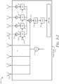
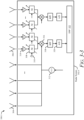
- FIGS. 3-1 , 3-2 , and 3-3 illustrate example conceptual diagrams of a radar system that uses Spatial-Block CDM for MIMO waveforms, in accordance with techniques of this disclosure.
- FIGS. 3-1 to 3-3 illustrate example conceptual diagrams 300-1, 300-2, and 300-3 of, respectively, radar systems 302-1, 302-2, and 302-3 (collectively radar systems 302).
- the radar systems 302 are each configured to apply Spatial-Block CDM for MIMO waveforms using different hardware configurations.
- the radar systems 302 are examples of the radar system 104.
- the conceptual diagrams 300-1, 300-2, and 300-3 each illustrate distinct components of the radar systems 302, but some or all of these components may be combined into a different (e.g., larger, smaller) set of distinct components.
- the radar system 302-1 includes multiple transmitters 304, which are illustrated as antenna elements in this example, configured to transmit respective EM signals.
- the radar system 302-1 uses the transmitted EM signals to detect any objects 106 in the vicinity of the vehicle 102, and which are within the field-of-view 108.
- the transmitters 304 can transmit a linear frequency-modulated signal (e.g., chirping signal) in some implementations. In other implementations, the transmitters 304 can transmit a phase-modulated continuous wave (PMCW) signal or a pulse signal (e.g., unmodulated signal).
- the transmitted EM signals can be any viable signal used for radar.
- the radar system 302-1 also includes multiple receivers 306, which are illustrated as antenna elements in this example, configured to receive reflected EM signals reflecting by the objects 106.
- the radar system 302-1 includes a processor and CRM, which can be the processor 114 and the CRM 116 of FIG. 1 .
- the CRM of the radar system 302-1 can maintain instructions that, when executed by the processor of the radar system 302-1, cause that processor to control the transmitters 304 or phase shifters 308.
- the processor of the radar system 302-1 can use the waveform generator 120 to control the phase shift applied or introduced to the transmitted EM signals.
- the polyphase shifters 308 are an example of the phase shifters 118. A phase shift applied or introduced to one or more EM signal pulses transmitted by the transmitters 304 can be controlled using these polyphase shifters 308. Each of the polyphase shifters 308 has multiple potential output stages (e.g., 4, 8, 16, 32, 64, 128, or 256 stages).
- the processor of the radar system 302-1 can provide a polyphase control signal 310 to the polyphase shifters 308 to control or set the phase stage of each polyphase shifter 308.
- the polyphase control signal 310 can be a multiple-bit signal (e.g., 6-bit, 8-bit, 12-bit, 16-bit, 24-bit, or 32-bit), allowing the polyphase shifters 308 to have more than two phase stages.
- a six-bit polyphase shifter 308 has up to 64 potential phase stages.
- the increased number of potential phase stages provides more flexibility (e.g., than binary phase shifters can provide) in Spatial-Block CDM schemes applied by the radar system 302-1.
- the radar system 302-1 passes the respective received EM signals through band-pass filters (BPFs) 318 and analog-to-digital converters (ADCs) 320 before analyzing them with a digital signal processor (DSP) 322.
- the DSP 322 can make one or more determinations regarding the objects 106, including resolving Doppler ambiguities.
- the BPFs 318 can pass frequencies in the received EM signals within a specific range and reject or attenuate frequencies outside this range. In other implementations, the radar system 302-1 can use additional or different filters, including low-pass filters or high-pass filters.
- the ADCs 320 converts the analog EM signals into a digital signal.
- the radar systems 302-2 and 302-3 can include similar components as depicted for the radar system 302-1.
- the radar systems 302-2 and 302-3 include the transmitters 304, receivers 306, a processor, CRM, polyphase shifters 308, VCO 312, LNAs 314, the mixer 316, the BPF 318, the ADC 320, and the DSP 322.
- the polyphase shifters 308 are operatively coupled to the LNAs 314 and the mixer 316 in the receiver paths of the radar systems 302-2 and 302-3 to asymmetrically shift the frequency or Doppler frequency of the reflected EM signals.
- the polyphase shifters 308 are operatively coupled to each receive channel and then operatively coupled to a single down-conversion or analog-to-digital conversion channel.
- the polyphase shifters 308 are operatively coupled to each receive channel and a subset of the receive channels or polyphase shifters 308 are then operatively coupled to a down-conversion or analog-to-digital conversion channel.
- the radar system 302-3 includes two polyphase shifters 308 or receive channels per down-conversion or analog-to-digital conversion channel.
- the radar system 302-3 can include another number of polyphase shifters 308 or receive channels per down-conversion or analog-to-digital conversion channel, resulting in N receive groups with M receive channels per receive group.
- the polyphase shifters 308 can also be operatively coupled in between other components in the receiver paths, including between the receivers 306 and the LNAs 314.
- the polyphase shifters 308 are not operatively coupled to the transmitters 304 but instead respectively associated with the receivers 306.
- the polyphase shifters 308 can introduce or apply an asymmetrical phase shift to the received EM signals.
- the radar system 302-2 or 302-3 can combine (e.g., superimpose) the signals received by one or more of the receivers 306 prior to analog-to-digital conversion by the ADC 320.
- each polyphase shifter 308 has multiple potential output stages (e.g., 4, 8, 16, 32, 64, 128, or 256 stages).
- the processor of the radar systems 302-2 or 302-3 can provide the polyphase control signal 310 to the polyphase shifters 308 to control or set the phase stage of each polyphase shifter 308.
- the polyphase control signal 310 can be a multiple-bit signal (e.g., 6-bit, 8-bit, 12-bit, 16-bit, 24-bit, or 32-bit), giving the polyphase shifters 308 more than two phase stages.
- the increased number of potential phase stages provides more flexibility in an FDM coding scheme applied by the radar system 302-2 to the received EM signals than binary phase shifters can provide.
- FIGS. 4 , 5 , 6 , and 7 each illustrate graphical representations of example MIMO waveforms for a radar system using Spatial-Block CDM, in accordance with techniques of this disclosure.
- the radar system 104 and/or the radar systems 302 can adopt any of the waveforms, or adaptions thereof, to detect mixed-Doppler intervals, resolve ambiguity, and/or perform analog beamforming.
- These example waveforms may be modified and/or used as basis for more complex waveforms.
- the example waveforms enable transmission and/or reception of EM signals for implementing different variations of Spatial-Block CDM.
- FIG. 4 illustrates a graphical representation of a MIMO waveform 400 that can generally be used for mixed-Doppler interval detection and resolving velocities using Spatial-Block CDM techniques.
- the waveform 400 supports a MIMO radar system having a quantity N of channels. Each of the channels simultaneously transmits a corresponding radar signal s 1 , ..., s N .
- FIG. 4 shows two spatial blocks, each having a duration T p and being evenly divided into a quantity M of slots. M is chosen to be greater than N.
- the quantity M of the slots can be greater than the quantity N of the channels by one; in other cases, the quantity M of the slots is greater than the quantity N of the channels by more than one.
- Each slot has the same duration T s . Given this, T s multiplied by M produces T p .
- All N channels are activated with a pre-defined phase shift that can vary depending on slot.
- the waveform 400 supports a signal that has a pre-defined phase shift ⁇ ij , where i is the channel (e.g., ranging one to N) and j is the slot (e.g., ranging one to M).
- i is the channel (e.g., ranging one to N)
- j is the slot (e.g., ranging one to M).
- i is the channel (e.g., ranging one to N)
- j the slot (e.g., ranging one to M).
- a set of M complex observations are obtained for each Doppler bin by applying a FFT across a combination of the N channels at each of the M slots.
- Y is a set including elements y 1 , y 2 , ..., y M , each of which represent a complex observations from one of the M FFTs applied at one Doppler bin
- v p is the measured Doppler from applying an FFT across that spatial block.
- s be a set including elements s 1 , s 2 , ..., s N represent the complex signal amplitude of the N channels at the same Doppler bin.
- Equation 5 can be applied to detect whether each spatial block has a mixed-Doppler interval.
- e j ⁇ 1,1 ⁇ e j ⁇ N , 1 ⁇ ⁇ ⁇ e j ⁇ 1 , M ⁇ e j ⁇ N , M ⁇ s 1 ⁇ s N y 1 e ⁇ j 1 ⁇ 1 ⁇ ⁇ y M e ⁇ j M ⁇ 1 ⁇
- Equation 5 can be rewritten in vector form, as shown in Equation 7:
- Qs Ya ⁇
- the term Q is equal to e j ⁇ 1,1 ... e j ⁇ N , 1 ⁇ ⁇ ⁇ e j ⁇ 1 , M ... e j ⁇ N , M
- a ( ⁇ ) is equal to e ⁇ j 1 ⁇ 1 ⁇ ⁇ e ⁇ j M ⁇ 1 ⁇ .
- Equation 14 argmin ⁇ 2 ⁇ ⁇ ⁇ ⁇ 1 , ... , ⁇ M
- Equation 8 can be solved using the determined phase offset ⁇ to reconstruct the signals s.
- the radar system 104 and/or the radar systems 302 can detect whether a mixed-Doppler interval occurs during each spatial block.
- the mixed-Doppler interval module 122 can determine, based on the complex observations Y, whether a Doppler phase shift between two of the M slots has a single possible value for the phase offset ⁇ or multiple possible values for the phase offset ⁇ . In cases where the result of Equation 14 produces more than one possible phase offset ⁇ , a mixed-Doppler interval condition exists.
- the mixed-Doppler interval module 122 may output an indication of a mixed Doppler interval detected in that spatial block.
- the mixed-Doppler interval module 122 can determine whether a mixed-Doppler interval occurs even if a single possible value for the phase offset ⁇ can be derived from Equation 14. Because the square error function ⁇ 2 ( ⁇ ) produces a term that is related to signal to noise ratio, a mixed-Doppler interval can be detected by evaluating a minimum square error obtained from Equation 14. Assuming ⁇ min 2 is a minimum error, it can be compared against a threshold to determine whether a mixed-Doppler interval is detected. The threshold can be based on the signal to noise ratio.
- the mixed-Doppler interval module determines whether a minimum error caused by the Doppler phase shift of the single possible value satisfies a mixed interval threshold.
- An indication of a mixed-Doppler interval detected in that spatial block can be output by the mixed-Doppler interval module 122 in response to determining that the minimum error satisfies the mixed interval threshold.
- FIG. 5 illustrates a graphical representation of a MIMO waveform 500 for MIMO radar systems having a quantity of two channels.
- Each of the two channels e.g., channel 1 and channel 2 simultaneously transmits a corresponding radar signal (e.g., s 1 or s 2 ) for the duration of each spatial block.
- a corresponding radar signal e.g., s 1 or s 2
- Two spatial blocks are illustrated in FIG. 5 ; each spatial block is evenly divided into three slots, which satisfies conditions for resolving velocities using Spatial-Block CDM because the three slots represents a greater quantity than the two channels.
- the radar system 104 and/or the radar systems 302 can apply Spatial-Block CDM techniques by defining the waveform 500 as follows: Q is equal to 1 1 1 1 1 1 ⁇ 1 , s is equal to s 1 s 2 , and Y is equal to y 1 y 2 e ⁇ j ⁇ y 3 e ⁇ j 2 ⁇ .
- the middle slot has a code that is a repeat of a code of the first slot.
- the last slot has a different code than the first and second slots.
- the waveform generator 120 With the waveform generator 120 causing transmissions of the waveform 500, and with the mixed-Doppler interval module 122 evaluating reflections to the waveform 500, mixed-Doppler intervals can be detected, and velocities can be resolved without ambiguity.
- the waveform generator 120 can operate the MMIC 112 to produce the waveform 500. Because the radar system 104 is a MIMO system, non-coherent integration of the reflections is required to be performed across all dimensions of an antenna array in order to identify detections. Non-coherent integration can be performed in various ways.
- Spatial-Block CDM techniques to detect or resolve mixed-Doppler intervals can be applied before or after this non-coherent integration process occurs. That is, the complex observations may be associated with each of the range and Doppler measurements inferred prior to performing non-coherent integration across all channels. For example, a more complex process for implementing the square error function ⁇ 2 ( ⁇ ) involves using all the original complex observations Y , not just those associated with detections. The square error function ⁇ 2 ( ⁇ ) is solved for every range and Doppler bin, before non-coherent integration. In other cases, to reduce complexity, the complex observations only include those associated with detections inferred after performing non-coherent integration across all channels.
- a different implementation (which may be faster and/or less complex) pairs the complex observations Y down to only include those associated with detections inferred after range and Doppler processing.
- Applying the square error function ⁇ 2 ( ⁇ ) after applying non-coherent integration can simplify its solution; solutions to the square error function ⁇ 2 ( ⁇ ) only need to be found for a subset, as opposed to all, of the complex observations obtained.
- This implementation supports generation of analog beams that point at different angles during each slot to improve gain of the non-coherent integration at those angles. The gain is different depending on whether the square error function ⁇ 2 ( ⁇ ) is solved before non-coherent integration, or whether the square error function ⁇ 2 ( ⁇ ) is solved after, utilizing benefits of the analog beam formations.
- the radar system 104 forms a particular analog beam.
- the specific code of phase shifts applied by the phase shifters across the channels during each slot forms an analog beam directed at a particular angle.
- the analog beam formed during two or more of the slots can be directed at a same angle.
- the analog beam formed during at least one other of the slots is directed at a different angle than the analog beam formed during the two or more of the slots at the same angle.
- the first two slots can have an analog beam pointing at zero degrees
- the third slot may have a beam with a null at zero degrees but higher gains at other angles.
- the gain of this two channel example from resolving the square error function ⁇ 2 ( ⁇ ) after non-coherent integration occurs is approximately 8dB and may be more. This is at least 0.9dB more than if no analog beamforming occurs.
- the 8dB or more of gain is based on 6dB from the power of the two channels and the coherently integrated beam, 3.7dB from the non-coherent integration over the three slots, and -1.7dB because one channel has no gain.
- a highest gain from analog beamforming this way is not at zero degrees but at approximately plus or minus 17.8 degrees, which is where the three analog beams intercept. Between plus or minus 44.68 degrees, the non-coherent integration gain through this implementation is higher or equal to the gain obtained when the square error function ⁇ 2 ( ⁇ ) is resolved before non-coherent integration occurs.
- the radar system 104 may realize a higher gain across a wide range of the field of view 108. Consistent, but lower gain is realized, when analog beamforming is not used.
- FIG. 6 illustrates a graphical representation of a MIMO waveform 600 for MIMO radar systems having a quantity of four channels.
- the waveform 500 can be generated when the phase shifters 118 are binary shifters.
- the radar system 104 uses polyphase shifters as the phase shifters 118 when generating a waveform like the waveform 600.
- each of the four channels of the radar system 104 simultaneously transmits a corresponding radar signal (e.g., s 1 , s 2 ., s 3 , s 4 ) for the duration of each spatial block.
- a single spatial block is illustrated in FIG.
- each spatial block is evenly divided into five slots, which satisfies conditions for resolving velocities using Spatial-Block CDM because the five slots represent at least one more than the four channels.
- the radar system 104 and/or the radar systems 302 can apply Spatial-Block CDM techniques by defining the waveform 600 as follows: Q is equal to 1 1 1 1 1 1 1 1 1 1 1 ⁇ 1 1 ⁇ 1 1 j ⁇ 1 j 1 ⁇ j 1 j , s is equal to s 1 s 2 s 3 s 4 , and Y is equal to y 1 y 2 e ⁇ j ⁇ y 3 e ⁇ j 2 ⁇ y 4 e ⁇ j 3 ⁇ y 5 e ⁇ j 4 ⁇ .
- the second slot has a code that is a repeat of a code of the first slot.
- the third, fourth, and fifth slots each have a unique code, different than the other slots.
- the polyphase shifters allow the waveform 600 to be generated by the radar system 104, which can provide great flexibility in forming analog beams pointed at a variety of different angles (e.g., four different angles in this example). Many different phase combinations can be provided with four channels, specific phase codes may be used depending on application.
- Q is set to have sufficient rows to support the N channels, however, the quantity of columns for Q need be greater than the N channels.
- implementations in which analog beams are formed that are directed at similar (e.g., close) angles it is possible that a value of ( Q H Q ) -1 is small. As this determinant value approaches zero, resolving the square error function ⁇ 2 ( ⁇ ) becomes difficult.
- FIG. 7 illustrates a graphical representation of a MIMO waveform 700 that can generally be used for mixed-Doppler interval detection and resolving velocities using Spatial-Block CDM techniques.
- a MIMO waveform 700 that can generally be used for mixed-Doppler interval detection and resolving velocities using Spatial-Block CDM techniques.
- two or more targets fall into a same Doppler bin, they have an aliased Doppler value v p .
- v s When these targets have different velocities v s , then a mixed-Doppler interval occurs; there is no single phase offset ⁇ that can correct a Doppler phase offset in the L*N observations Y including y 1 , ..., y L*N .
- Generation of the waveform 700 can implement a particular Spatial-Block CDM scheme designed to be robust against mixed Doppler intervals.
- the waveform 700 supports a MIMO radar system having a quantity N of channels. Each of the channels simultaneously transmits a corresponding radar signal s 1 , ..., s N . Each spatial block is evenly divided into a quantity of M slots set equal to a product of L and N. Each slot has the same duration T s , which when multiplied by the product of L and N, produces T p for each spatial block of the waveform 700.
- L is chosen to be greater than or equal to three. Every L slots in the spatial block is a group of slots that use a unique code of phase shifts for all slots in that group. For example, L is equal to three in the waveform 700. The first three slots use a first code of predefined phase shifts ⁇ 11 , ..., ⁇ N1 .
- the next three slots use a second code of predefined phase shifts ⁇ 12 , ..., ⁇ N2 .
- This sequence repeats until the last three slots, where a code of predefined phase shifts ⁇ 1N , ..., ⁇ NN is used.
- the larger the value of L the more mixed targets can be recovered.
- L is set to three or more, a quantity of L minus one of mixed targets can be recovered.
- Equation 16 provides a formula for utilizing the waveform 700 to resolve velocities during mixed-Doppler intervals:
- the phase offset is estimated using Equation 6.
- N two-dimensional FFTs can be performed across all L slots of K blocks.
- v p is determined across each block K
- v s is determined across each of the M (e.g., L*N) slots.
- the two-dimensional FFTs can be separated to improve computation efficiency.
- Equation 19 can provide the signals s 1 through s N .
- FIG. 8 illustrates an example process 800 for a radar system that uses Spatial-Block CDM for MIMO waveforms, in accordance with techniques of this disclosure.
- the process 800 is shown as sets of operations (or acts) performed, but not necessarily limited to the order or combinations in which the operations are shown herein. Further, any of one or more of the operations may be repeated, combined, or reorganized to provide other methods.
- the process 800 can be executed by the radar system 104 and/or the radar systems 302.
- the processor 114 can execute instructions stored on the CRM 116 to perform the operations or acts described below.
- multiple transmitters are caused to simultaneously emit multiple electromagnetic (EM) signals across multiple channels as sequential spatial blocks having multiple slots outnumbering the channels.
- the waveform generator 120 may operate the MMIC 112 to configure the radar system 104 to output a variation of any of the waveforms 400, 500, 600, or 700.
- multiple receivers are caused to obtain reflections of the EM signals from one or more objects.
- the waveform generator 120 may further operate the radar system 104 to receive the reflections and store them as complex observations.
- phase shifters are caused to introduce at least one phase shift in the EM signals or the reflections.
- each slot corresponds to a specific code of phase shifts applied by the phase shifters 118 across the channels during that slot.
- a Fast-Fourier Transformation is applied to the reflections to generate complex observations at each of the channels during each of the slots.
- the processor 114 and/or the MMIC 112 generate Y including y 1 to y M to generate a complex measurement for each slot of a particular channel.
- the processor 114 may solve Equation 5 for the phase offset ⁇ , including determining the square error function ⁇ 2 ( ⁇ ). Then from Equation 14, one or more possible values of the phase offset ⁇ are determined.
- a Yes condition out of 810 leads to 812.
- an indication of a mixed Doppler interval detected in that spatial block is output.
- the mixed-Doppler interval module 122 can determine that multiple possible values of the phase offset ⁇ exist, which indicates that a mixed-Doppler interval occurred. This can be resolved using the techniques described above.
- a No condition out of 810 leads to 814.
- 814 responsive to determining that the Doppler phase shift between two of the slots has only one possible value, whether a minimum error caused by the Doppler phase shift of the single possible value satisfies a mixed interval threshold is determined. For example, a minimum phase offset ⁇ can be determined from the square error function ⁇ 2 ( ⁇ ).
- a Yes condition out of 814 leads to 812, where an indication of the mixed Doppler interval detected in that spatial block is output in response to determining that the minimum error satisfies the mixed interval threshold. For example, if the error introduced by the phase offset ⁇ is too high and the mixed interval threshold is satisfied, a mixed-Doppler interval exists.
- a No condition out of 814 leads to 816.
- the complex observations for each of the slots are output.
- the complex measurements are output for use in further processing (e.g., Doppler processing or angle estimating). This can include compensating the complex observations for the minimum error caused by the Doppler phase shift. For example, if the error is below the mixed interval threshold, then the error is not sufficient for indicating that a mixed-Doppler interval exists.
- the complex measurements can be compensated, and individual velocities of targets can be resolved.
- FIG. 9 illustrates an example scenario 900 for analog beamforming with a vehicle radar configured to adopt Spatial-Block CDM for MIMO waveforms, in accordance with techniques of this disclosure.
- the scenario 900 is depicted as a birds eye view of the vehicle 102 during execution (e.g., by the driving systems 206) of vehicle functions that rely on radar data output from the radar system 104.
- Some vehicle functions depend on the radar system 104 being able to provide sufficient coverage and/or sufficient sensitivity for improved driving and safety (e.g., near the object 106).
- the radar system 104 is configured to transmit and receive radar signals with increased sensitivity (e.g., increase resolution of the field of view 108) and/or increased coverage (e.g., increase to size of the field of view 108) by using the Spatial-Block CDM for MIMO waveform examples, as described above.
- the waveform 400 supports a MIMO radar system having a quantity N of channels.
- Each of the channels simultaneously transmits a quantity of N radar signals s 1 , ..., s N , for a duration T p , which is evenly divided into a quantity of M time slots greater than N (e.g., by one, by more than one) and each having a duration T s .
- the radar system 104 is configured to operate using the waveform 400 to increase coverage (a size of the field of view 108) provided by the transmitters and receivers.
- the radar system 104 is configured to apply a specific code of phase shifts (e.g., using the phase shifters 118) across an entire set of N channels during slots 902-1, 902-2, 902-3, and 902-M.
- the waveform 400 enables the MMIC 112 of the radar system 104 to form a respective analog beam 904-1, 904-2, 904-3, and 904-M focused around a respective angle ⁇ 1 , ⁇ 2 , ⁇ 4 , and ⁇ M , or respective angular range (e.g., ⁇ 1 ⁇ ⁇ 1 , ⁇ 2 ⁇ ⁇ 2 , ⁇ 3 ⁇ ⁇ 3 , and ⁇ M ⁇ ⁇ M ) with any radar system having multiple transmit and/or receive channels.
- the analog beam formed during at least one first slot is directed at a first angle that is a different angle than a second angle associated with the analog beam formed during a second slot to increase coverage provided by the transmitters and the receivers at both angles.
- the analog beam 904-1 is formed during the slot 902-1 to provide coverage around the angle ⁇ 1 in the field of view 108
- the analog beam 904-2 is formed during the slot 902-2 to extend the coverage provided during the slot 902-1 to provide additional coverage and include the angle ⁇ 2 in the field of view 108.
- the slots 902-3 and 902-M provide additional coverage and increase the field of view 108 and expand coverage to include additional fields of detection at the angles ⁇ 3 and ⁇ M .
- the radar system 104 is configured to operate using the waveform 400 to increase sensitivity (e.g., resolution) provided by the transmitters and receivers at a particular region in the field of view 108.
- the radar system 104 forms an analog beam during two or more of the M slots at around a same angle.
- improved resolution can increase accuracy of moving target detections obtained from particular angle or angular range.
- the analog beam 904-1 can be formed during the slot 902-1 through transmission of the waveform 400 to provide coverage around the angle ⁇ 1 .
- the analog beam 904-2 may be a duplicate of (or similar to) the analog beam 904-1; the angle ⁇ 2 may be approximate or equal to the angle ⁇ 1 .
- the analog beam 904-2 is formed during the slot 902-2.
- the radar system 104 may increase sensitivity at that region of the field of view 108.
- the slots 902-3 and 902-M can be used to provide additional additional coverage and/or increased sensitivity at different or similar viewing positions in the field of view 108, depending on desired radar based vehicle functionality.
- "at least one of: a, b, or c” is intended to cover a, b, c, a-b, a-c, b-c, and a-b-c, as well as any combination with multiples of the same element (e.g., a-a, a-a-a, a-a-b, a-a-c, a-b-b, a-c-c, b-b, b-b-b, b-b-c, c-c, and c-c-c or any other ordering of a, b, and c).
Landscapes
- Engineering & Computer Science (AREA)
- Radar, Positioning & Navigation (AREA)
- Remote Sensing (AREA)
- Computer Networks & Wireless Communication (AREA)
- Physics & Mathematics (AREA)
- General Physics & Mathematics (AREA)
- Radar Systems Or Details Thereof (AREA)
Claims (14)
- Verfahren, umfassend:Bewirken (802), durch mindestens einen Prozessor (114), dass mehrere Sender (304) eines Radarsystems (104) gleichzeitig mehrere elektromagnetische Signale (EM-Signale) über mehrere Kanäle aussenden, indem bewirkt wird, dass die Sender (304) die EM-Signale als sequentielle räumliche Blöcke aussenden, wobei jeder räumliche Block mehrere Zeitfenster aufweist, die die Kanäle zahlenmäßig übertreffen;Bewirken (804), durch den Prozessor (114), dass mehrere Empfänger (306) des Radarsystems (104) Reflexionen der EM-Signale von einem oder mehreren Objekten (106) erhalten;Bewirken (806), durch den Prozessor (114), dass mehrere Phasenschieber (118) des Radarsystems (104) mindestens eine Phasenverschiebung in die EM-Signale oder die Reflexionen einführen, wobei jedes Zeitfenster einem bestimmten Code von Phasenverschiebungen entspricht, der von den Phasenschiebern (118) über die Kanäle während dieses Zeitfensters angewendet wird;Anwenden (808), durch den Prozessor (114), einer jeweiligen Fast-FourierTransformation auf die Reflexionen, um komplexe Beobachtungen an jedem der Kanäle während jedes der Zeitfenster zu erzeugen;Feststellen (810), durch den Prozessor (114), basierend auf den komplexen Beobachtungen, ob eine Doppler-Phasenverschiebung zwischen zwei der Zeitfenster mehrere mögliche Werte aufweist, wobei der bestimmte Code von Phasenverschiebungen, der mindestens zwei der Zeitfenster entspricht, ein gleicher Code von Phasenverschiebungen ist; undals Reaktion auf das Feststellen (810), dass die Doppler-Phasenverschiebung zwischen zwei der Zeitfenster mehrere mögliche Werte aufweist, Ausgeben (816), durch den Prozessor (114), einer Anzeige eines gemischten Doppler-Intervalls, das in diesem räumlichen Block detektiert wird.
- Verfahren nach Anspruch 1, ferner umfassend:als Reaktion auf das Feststellen (810), dass die Doppler-Phasenverschiebung zwischen zwei der Zeitfenster nicht mehrere mögliche Werte aufweist, Feststellen, durch den Prozessor (114), ob ein minimaler Fehler, der durch die Doppler-Phasenverschiebung eines einzigen möglichen Wertes verursacht wird, einen gemischten Intervallschwellenwert erfüllt; undAusgeben (812), durch den Prozessor (114), der Anzeige des gemischten Doppler-Intervalls, das in diesem räumlichen Block detektiert wird, als Reaktion auf das Feststellen (814), dass der minimale Fehler den gemischten Intervallschwellenwert erfüllt.
- Verfahren nach Anspruch 2, ferner umfassend:
als Reaktion auf das Feststellen (814), dass der minimale Fehler, der durch die Doppler-Phasenverschiebung des einzigen möglichen Wertes verursacht wird, den gemischten Intervallschwellenwert nicht erfüllt, Ausgeben (816), durch den Prozessor (114), der komplexen Beobachtungen für jedes der Zeitfenster zur Verwendung bei der Doppler-Verarbeitung oder Winkelschätzung. - Verfahren nach Anspruch 2 oder 3, ferner umfassend:
als Reaktion auf das Feststellen (814), dass der minimale Fehler, der durch die Doppler-Phasenverschiebung des einzigen möglichen Wertes verursacht wird, den gemischten Intervallschwellenwert nicht erfüllt, Kompensieren der komplexen Beobachtungen für den minimalen Fehler, der durch die Doppler-Phasenverschiebung verursacht wird. - Verfahren nach einem der vorhergehenden Ansprüche, wobei eine Anzahl der Zeitfenster um mindestens eins größer als eine Anzahl der Kanäle ist.
- Verfahren nach einem der vorhergehenden Ansprüche, wobei der
bestimmte Code von Phasenverschiebungen, der mindestens zwei anderen der Zeitfenster entspricht, ein eindeutiger Code von Phasenverschiebungen ist. - Verfahren nach einem der vorhergehenden Ansprüche, wobei die Zeitfenster jeweils eine Gruppe von Zeitfenstern umfassen, die einen eindeutigen Code von Phasenverschiebungen für alle Zeitfenster in dieser Gruppe verwenden.
- Verfahren nach einem der vorhergehenden Ansprüche, wobei:die komplexen Beobachtungen Detektionen zugeordnet sind, die nach dem Durchführen einer nicht kohärenten Integration über alle Kanäle abgeleitet werden; oderdie komplexen Beobachtungen nach dem Durchführen einer nicht kohärenten Integration über alle Kanäle abgeleitet werden.
- Verfahren nach einem der vorhergehenden Ansprüche, wobei:der bestimmte Code von Phasenverschiebungen, der von den Phasenschiebern (118) über die Kanäle während jedes Zeitfensters angewendet wird, einen analogen Strahl formt, der in einem speziellen Winkel in ein Sichtfeld (108) hinein gerichtet ist,wobei der analoge Strahl, der während zweier oder mehrerer der Zeitfenster geformt wird, insbesondere in einem gleichen Winkel innerhalb eines Sichtfelds (108) des Systems gerichtet ist, um die Empfindlichkeit der Sender (304) und der Empfänger (306) in diesem gleichen Winkel zu erhöhen.
- Verfahren nach Anspruch 9, wobei der analoge Strahl, der während
mindestens eines ersten Zeitfensters geformt wird, in einem ersten Winkel gerichtet ist, der ein anderer Winkel als ein zweiter Winkel ist, der dem analogen Strahl zugeordnet ist, der während eines zweiten Zeitfensters geformt wird, um eine Abdeckung zu erhöhen, die von den Sendern (304) und den Empfängern (306) in beiden Winkeln bereitgestellt wird. - Verfahren nach einem der vorhergehenden Ansprüche, wobei die
Phasenschieber (118) binäre Phasenschieber oder Polyphasenschieber (308) umfassen. - Verfahren nach einem der vorhergehenden Ansprüche, wobei das
Ausgeben (812) der Anzeige des gemischten Doppler-Intervalls das Erzeugen von Multiple Input Multiple Output, MIMO, Radardaten für ein Automobil basierend auf der Anzeige des gemischten Doppler-Intervalls umfasst. - System, umfassend:mehrere Sender (304), die konfiguriert sind, um gleichzeitig mehrere elektromagnetische Signale (EM-Signale) über mehrere Kanäle auszusenden;mehrere Empfänger (306), die konfiguriert sind, um Reflexionen der EM-Signale von einem oder mehreren Objekten (106) zu erhalten;mehrere Phasenschieber (118), die konfiguriert sind, um mindestens eine Phasenverschiebung in die EM-Signale oder die Reflexionen einzuführen; undeinen Prozessor (114), der konfiguriert ist, um das Verfahren nach einem der vorhergehenden Ansprüche durchzuführen.
- Computerlesbares Medium (116), das Anweisungen umfasst, die, wenn sie
ausgeführt werden, den Prozessor (114) des Systems nach Anspruch 13 veranlassen, das Verfahren nach einem der vorhergehenden Ansprüche 1-12 durchzuführen.
Applications Claiming Priority (2)
| Application Number | Priority Date | Filing Date | Title |
|---|---|---|---|
| US202163252338P | 2021-10-05 | 2021-10-05 | |
| US17/929,984 US12449508B2 (en) | 2021-10-05 | 2022-09-06 | Spatial-block code division multiplexing (CDM) for multiple input multiple output (MIMO) waveforms |
Publications (2)
| Publication Number | Publication Date |
|---|---|
| EP4163664A1 EP4163664A1 (de) | 2023-04-12 |
| EP4163664B1 true EP4163664B1 (de) | 2024-11-27 |
Family
ID=83361110
Family Applications (1)
| Application Number | Title | Priority Date | Filing Date |
|---|---|---|---|
| EP22196046.1A Active EP4163664B1 (de) | 2021-10-05 | 2022-09-16 | Raumblock-codemultiplexing (cdm) für mimo-wellenformen |
Country Status (3)
| Country | Link |
|---|---|
| US (1) | US12449508B2 (de) |
| EP (1) | EP4163664B1 (de) |
| CN (1) | CN115932857A (de) |
Families Citing this family (2)
| Publication number | Priority date | Publication date | Assignee | Title |
|---|---|---|---|---|
| US20240426976A1 (en) * | 2023-06-20 | 2024-12-26 | Qualcomm Incorporated | Precoding Radar Receive Signals |
| WO2024263159A1 (en) * | 2023-06-21 | 2024-12-26 | Waveye, Inc. | System and method of determining a relative radial velocity of a radar target |
Family Cites Families (8)
| Publication number | Priority date | Publication date | Assignee | Title |
|---|---|---|---|---|
| US7474262B2 (en) | 2005-07-01 | 2009-01-06 | Delphi Technologies, Inc. | Digital beamforming for an electronically scanned radar system |
| EP2629113B1 (de) | 2009-04-06 | 2017-04-26 | Conti Temic microelectronic GmbH | Radarsystem mit anordnungen und verfahren zur entkopplung von sende- und empfangssignalen sowie unterdrückung von störeinstrahlungen |
| US9952319B2 (en) * | 2015-12-08 | 2018-04-24 | Delphi Technologies, Inc. | Residue cancellation for automated vehicle MIMO radar |
| US10921436B2 (en) | 2018-08-13 | 2021-02-16 | Nxp B.V. | MIMO radar coding for resolving velocity ambiguity |
| DE102018121987A1 (de) | 2018-09-10 | 2020-03-12 | Infineon Technologies Ag | Frequenzmoduliertes Dauerstrich-Radarsystem |
| DE102018221085A1 (de) | 2018-12-06 | 2020-06-10 | Robert Bosch Gmbh | Mehrdeutigkeitsauflösung für MIMO-Radarsystem |
| US11054516B2 (en) * | 2018-12-18 | 2021-07-06 | Nxp Usa, Inc. | Extended doppler FMCW code division MIMO radar |
| DE102020202498A1 (de) * | 2020-02-27 | 2021-09-02 | Robert Bosch Gmbh | MIMO-Radarsystem |
-
2022
- 2022-09-06 US US17/929,984 patent/US12449508B2/en active Active
- 2022-09-16 EP EP22196046.1A patent/EP4163664B1/de active Active
- 2022-10-09 CN CN202211237324.8A patent/CN115932857A/zh active Pending
Also Published As
| Publication number | Publication date |
|---|---|
| EP4163664A1 (de) | 2023-04-12 |
| CN115932857A (zh) | 2023-04-07 |
| US12449508B2 (en) | 2025-10-21 |
| US20230104290A1 (en) | 2023-04-06 |
Similar Documents
| Publication | Publication Date | Title |
|---|---|---|
| US11789143B2 (en) | Radar apparatus, system, and method of generating angle of arrival (AoA) information | |
| US11163055B2 (en) | Time and frequency synchronization for spread radar systems | |
| US20190204435A1 (en) | A vehicle radar system | |
| US11899133B2 (en) | Method for determining at least one object information item of at least one target object which is sensed with a radar system, in particular of a vehicle, radar system and driver assistance system | |
| JP2023073522A (ja) | 電子機器、電子機器の制御方法、及び電子機器の制御プログラム | |
| EP4016116B1 (de) | Signalübertragungsverfahren und -vorrichtung, signalverarbeitungsverfahren und -vorrichtung sowie radarsystem | |
| EP3045934A1 (de) | Radarvorrichtung, fahrzeug und verfahren zur erkennung der geschwindigkeit eines bewegten körpers | |
| CN113093131B (zh) | 一种信号处理方法及装置 | |
| US20240201358A1 (en) | Object Range and Velocity Detection from Varying Radar Pulse Repetition Times | |
| EP4163664B1 (de) | Raumblock-codemultiplexing (cdm) für mimo-wellenformen | |
| EP4016884B1 (de) | Signalübertragungsverfahren und -vorrichtung, signalverarbeitungsverfahren und -vorrichtung sowie radarsystem | |
| EP3825717B1 (de) | Elektronische vorrichtung, steuerungsverfahren für eine elektronische vorrichtung und steuerungsprogramm für eine elektronische vorrichtung | |
| CN111630406B (zh) | 确定物体信息项的方法和雷达系统、车辆驾驶员辅助系统 | |
| EP4053585B1 (de) | Frequenzmultiplexen mit polyphasenschiebern | |
| CN115015935B (zh) | 利用多相移位器的频分复用 | |
| US12306335B2 (en) | Method for determining at least one piece of object information about at least one object sensed by means of a radar system and radar system | |
| CN114924250A (zh) | 用于多个雷达信道的慢时间调制 | |
| EP4293389A2 (de) | Verfahren und systeme zur radarwellenformdiversität | |
| US12248063B2 (en) | Electronic device, method for controlling electronic device, and program for controlling electronic device | |
| JP2023034318A (ja) | 電子機器、電子機器の制御方法、及びプログラム | |
| US12546856B2 (en) | Electronic device, method for controlling electronic device, and program | |
| US12571896B2 (en) | Asymmetrical frequency-division multiplexing for radar systems | |
| LU100106B1 (en) | Time and Frequency Synchronization for Spread Radar Systems |
Legal Events
| Date | Code | Title | Description |
|---|---|---|---|
| PUAI | Public reference made under article 153(3) epc to a published international application that has entered the european phase |
Free format text: ORIGINAL CODE: 0009012 |
|
| STAA | Information on the status of an ep patent application or granted ep patent |
Free format text: STATUS: THE APPLICATION HAS BEEN PUBLISHED |
|
| AK | Designated contracting states |
Kind code of ref document: A1 Designated state(s): AL AT BE BG CH CY CZ DE DK EE ES FI FR GB GR HR HU IE IS IT LI LT LU LV MC MK MT NL NO PL PT RO RS SE SI SK SM TR |
|
| STAA | Information on the status of an ep patent application or granted ep patent |
Free format text: STATUS: REQUEST FOR EXAMINATION WAS MADE |
|
| 17P | Request for examination filed |
Effective date: 20230821 |
|
| RBV | Designated contracting states (corrected) |
Designated state(s): AL AT BE BG CH CY CZ DE DK EE ES FI FR GB GR HR HU IE IS IT LI LT LU LV MC MK MT NL NO PL PT RO RS SE SI SK SM TR |
|
| RAP1 | Party data changed (applicant data changed or rights of an application transferred) |
Owner name: APTIV TECHNOLOGIES AG |
|
| RIC1 | Information provided on ipc code assigned before grant |
Ipc: G01S 13/02 20060101ALN20240726BHEP Ipc: G01S 13/931 20200101ALN20240726BHEP Ipc: G01S 13/42 20060101ALI20240726BHEP Ipc: G01S 13/58 20060101ALI20240726BHEP Ipc: G01S 13/32 20060101ALI20240726BHEP Ipc: G01S 13/26 20060101ALI20240726BHEP Ipc: G01S 13/00 20060101ALI20240726BHEP Ipc: G01S 13/34 20060101ALI20240726BHEP Ipc: G01S 7/35 20060101ALI20240726BHEP Ipc: G01S 7/02 20060101AFI20240726BHEP |
|
| GRAP | Despatch of communication of intention to grant a patent |
Free format text: ORIGINAL CODE: EPIDOSNIGR1 |
|
| STAA | Information on the status of an ep patent application or granted ep patent |
Free format text: STATUS: GRANT OF PATENT IS INTENDED |
|
| RAP3 | Party data changed (applicant data changed or rights of an application transferred) |
Owner name: APTIV TECHNOLOGIES AG |
|
| RIC1 | Information provided on ipc code assigned before grant |
Ipc: G01S 13/02 20060101ALN20240819BHEP Ipc: G01S 13/931 20200101ALN20240819BHEP Ipc: G01S 13/42 20060101ALI20240819BHEP Ipc: G01S 13/58 20060101ALI20240819BHEP Ipc: G01S 13/32 20060101ALI20240819BHEP Ipc: G01S 13/26 20060101ALI20240819BHEP Ipc: G01S 13/00 20060101ALI20240819BHEP Ipc: G01S 13/34 20060101ALI20240819BHEP Ipc: G01S 7/35 20060101ALI20240819BHEP Ipc: G01S 7/02 20060101AFI20240819BHEP |
|
| INTG | Intention to grant announced |
Effective date: 20240912 |
|
| GRAS | Grant fee paid |
Free format text: ORIGINAL CODE: EPIDOSNIGR3 |
|
| P01 | Opt-out of the competence of the unified patent court (upc) registered |
Free format text: CASE NUMBER: APP_52372/2024 Effective date: 20240918 |
|
| GRAA | (expected) grant |
Free format text: ORIGINAL CODE: 0009210 |
|
| STAA | Information on the status of an ep patent application or granted ep patent |
Free format text: STATUS: THE PATENT HAS BEEN GRANTED |
|
| AK | Designated contracting states |
Kind code of ref document: B1 Designated state(s): AL AT BE BG CH CY CZ DE DK EE ES FI FR GB GR HR HU IE IS IT LI LT LU LV MC MK MT NL NO PL PT RO RS SE SI SK SM TR |
|
| REG | Reference to a national code |
Ref country code: GB Ref legal event code: FG4D |
|
| REG | Reference to a national code |
Ref country code: CH Ref legal event code: EP |
|
| REG | Reference to a national code |
Ref country code: IE Ref legal event code: FG4D |
|
| REG | Reference to a national code |
Ref country code: DE Ref legal event code: R096 Ref document number: 602022008131 Country of ref document: DE |
|
| REG | Reference to a national code |
Ref country code: LT Ref legal event code: MG9D |
|
| REG | Reference to a national code |
Ref country code: NL Ref legal event code: MP Effective date: 20241127 |
|
| PG25 | Lapsed in a contracting state [announced via postgrant information from national office to epo] |
Ref country code: PT Free format text: LAPSE BECAUSE OF FAILURE TO SUBMIT A TRANSLATION OF THE DESCRIPTION OR TO PAY THE FEE WITHIN THE PRESCRIBED TIME-LIMIT Effective date: 20250327 Ref country code: HR Free format text: LAPSE BECAUSE OF FAILURE TO SUBMIT A TRANSLATION OF THE DESCRIPTION OR TO PAY THE FEE WITHIN THE PRESCRIBED TIME-LIMIT Effective date: 20241127 Ref country code: IS Free format text: LAPSE BECAUSE OF FAILURE TO SUBMIT A TRANSLATION OF THE DESCRIPTION OR TO PAY THE FEE WITHIN THE PRESCRIBED TIME-LIMIT Effective date: 20250327 |
|
| PG25 | Lapsed in a contracting state [announced via postgrant information from national office to epo] |
Ref country code: FI Free format text: LAPSE BECAUSE OF FAILURE TO SUBMIT A TRANSLATION OF THE DESCRIPTION OR TO PAY THE FEE WITHIN THE PRESCRIBED TIME-LIMIT Effective date: 20241127 Ref country code: NL Free format text: LAPSE BECAUSE OF FAILURE TO SUBMIT A TRANSLATION OF THE DESCRIPTION OR TO PAY THE FEE WITHIN THE PRESCRIBED TIME-LIMIT Effective date: 20241127 |
|
| REG | Reference to a national code |
Ref country code: AT Ref legal event code: MK05 Ref document number: 1746178 Country of ref document: AT Kind code of ref document: T Effective date: 20241127 |
|
| PG25 | Lapsed in a contracting state [announced via postgrant information from national office to epo] |
Ref country code: BG Free format text: LAPSE BECAUSE OF FAILURE TO SUBMIT A TRANSLATION OF THE DESCRIPTION OR TO PAY THE FEE WITHIN THE PRESCRIBED TIME-LIMIT Effective date: 20241127 |
|
| PG25 | Lapsed in a contracting state [announced via postgrant information from national office to epo] |
Ref country code: ES Free format text: LAPSE BECAUSE OF FAILURE TO SUBMIT A TRANSLATION OF THE DESCRIPTION OR TO PAY THE FEE WITHIN THE PRESCRIBED TIME-LIMIT Effective date: 20241127 |
|
| PG25 | Lapsed in a contracting state [announced via postgrant information from national office to epo] |
Ref country code: NO Free format text: LAPSE BECAUSE OF FAILURE TO SUBMIT A TRANSLATION OF THE DESCRIPTION OR TO PAY THE FEE WITHIN THE PRESCRIBED TIME-LIMIT Effective date: 20250227 |
|
| PG25 | Lapsed in a contracting state [announced via postgrant information from national office to epo] |
Ref country code: GR Free format text: LAPSE BECAUSE OF FAILURE TO SUBMIT A TRANSLATION OF THE DESCRIPTION OR TO PAY THE FEE WITHIN THE PRESCRIBED TIME-LIMIT Effective date: 20250228 Ref country code: LV Free format text: LAPSE BECAUSE OF FAILURE TO SUBMIT A TRANSLATION OF THE DESCRIPTION OR TO PAY THE FEE WITHIN THE PRESCRIBED TIME-LIMIT Effective date: 20241127 Ref country code: AT Free format text: LAPSE BECAUSE OF FAILURE TO SUBMIT A TRANSLATION OF THE DESCRIPTION OR TO PAY THE FEE WITHIN THE PRESCRIBED TIME-LIMIT Effective date: 20241127 |
|
| PG25 | Lapsed in a contracting state [announced via postgrant information from national office to epo] |
Ref country code: PL Free format text: LAPSE BECAUSE OF FAILURE TO SUBMIT A TRANSLATION OF THE DESCRIPTION OR TO PAY THE FEE WITHIN THE PRESCRIBED TIME-LIMIT Effective date: 20241127 |
|
| PG25 | Lapsed in a contracting state [announced via postgrant information from national office to epo] |
Ref country code: RS Free format text: LAPSE BECAUSE OF FAILURE TO SUBMIT A TRANSLATION OF THE DESCRIPTION OR TO PAY THE FEE WITHIN THE PRESCRIBED TIME-LIMIT Effective date: 20250227 |
|
| PG25 | Lapsed in a contracting state [announced via postgrant information from national office to epo] |
Ref country code: SM Free format text: LAPSE BECAUSE OF FAILURE TO SUBMIT A TRANSLATION OF THE DESCRIPTION OR TO PAY THE FEE WITHIN THE PRESCRIBED TIME-LIMIT Effective date: 20241127 |
|
| PG25 | Lapsed in a contracting state [announced via postgrant information from national office to epo] |
Ref country code: DK Free format text: LAPSE BECAUSE OF FAILURE TO SUBMIT A TRANSLATION OF THE DESCRIPTION OR TO PAY THE FEE WITHIN THE PRESCRIBED TIME-LIMIT Effective date: 20241127 |
|
| PG25 | Lapsed in a contracting state [announced via postgrant information from national office to epo] |
Ref country code: EE Free format text: LAPSE BECAUSE OF FAILURE TO SUBMIT A TRANSLATION OF THE DESCRIPTION OR TO PAY THE FEE WITHIN THE PRESCRIBED TIME-LIMIT Effective date: 20241127 |
|
| PG25 | Lapsed in a contracting state [announced via postgrant information from national office to epo] |
Ref country code: RO Free format text: LAPSE BECAUSE OF FAILURE TO SUBMIT A TRANSLATION OF THE DESCRIPTION OR TO PAY THE FEE WITHIN THE PRESCRIBED TIME-LIMIT Effective date: 20241127 |
|
| PG25 | Lapsed in a contracting state [announced via postgrant information from national office to epo] |
Ref country code: SK Free format text: LAPSE BECAUSE OF FAILURE TO SUBMIT A TRANSLATION OF THE DESCRIPTION OR TO PAY THE FEE WITHIN THE PRESCRIBED TIME-LIMIT Effective date: 20241127 |
|
| PG25 | Lapsed in a contracting state [announced via postgrant information from national office to epo] |
Ref country code: CZ Free format text: LAPSE BECAUSE OF FAILURE TO SUBMIT A TRANSLATION OF THE DESCRIPTION OR TO PAY THE FEE WITHIN THE PRESCRIBED TIME-LIMIT Effective date: 20241127 |
|
| PG25 | Lapsed in a contracting state [announced via postgrant information from national office to epo] |
Ref country code: IT Free format text: LAPSE BECAUSE OF FAILURE TO SUBMIT A TRANSLATION OF THE DESCRIPTION OR TO PAY THE FEE WITHIN THE PRESCRIBED TIME-LIMIT Effective date: 20241127 |
|
| REG | Reference to a national code |
Ref country code: DE Ref legal event code: R097 Ref document number: 602022008131 Country of ref document: DE |
|
| PG25 | Lapsed in a contracting state [announced via postgrant information from national office to epo] |
Ref country code: SE Free format text: LAPSE BECAUSE OF FAILURE TO SUBMIT A TRANSLATION OF THE DESCRIPTION OR TO PAY THE FEE WITHIN THE PRESCRIBED TIME-LIMIT Effective date: 20241127 |
|
| PLBE | No opposition filed within time limit |
Free format text: ORIGINAL CODE: 0009261 |
|
| STAA | Information on the status of an ep patent application or granted ep patent |
Free format text: STATUS: NO OPPOSITION FILED WITHIN TIME LIMIT |
|
| PGFP | Annual fee paid to national office [announced via postgrant information from national office to epo] |
Ref country code: DE Payment date: 20250814 Year of fee payment: 4 |
|
| PGFP | Annual fee paid to national office [announced via postgrant information from national office to epo] |
Ref country code: FR Payment date: 20250910 Year of fee payment: 4 |
|
| 26N | No opposition filed |
Effective date: 20250828 |