EP4163666A1 - Radarbasierte bewegungsklassifizierung unter verwendung einer oder mehrerer zeitreihen - Google Patents
Radarbasierte bewegungsklassifizierung unter verwendung einer oder mehrerer zeitreihen Download PDFInfo
- Publication number
- EP4163666A1 EP4163666A1 EP21201047.4A EP21201047A EP4163666A1 EP 4163666 A1 EP4163666 A1 EP 4163666A1 EP 21201047 A EP21201047 A EP 21201047A EP 4163666 A1 EP4163666 A1 EP 4163666A1
- Authority
- EP
- European Patent Office
- Prior art keywords
- time
- complex
- computer
- dimension
- implemented method
- Prior art date
- Legal status (The legal status is an assumption and is not a legal conclusion. Google has not performed a legal analysis and makes no representation as to the accuracy of the status listed.)
- Pending
Links
Images





Classifications
-
- G—PHYSICS
- G01—MEASURING; TESTING
- G01S—RADIO DIRECTION-FINDING; RADIO NAVIGATION; DETERMINING DISTANCE OR VELOCITY BY USE OF RADIO WAVES; LOCATING OR PRESENCE-DETECTING BY USE OF THE REFLECTION OR RERADIATION OF RADIO WAVES; ANALOGOUS ARRANGEMENTS USING OTHER WAVES
- G01S7/00—Details of systems according to groups G01S13/00, G01S15/00, G01S17/00
- G01S7/02—Details of systems according to groups G01S13/00, G01S15/00, G01S17/00 of systems according to group G01S13/00
- G01S7/41—Details of systems according to groups G01S13/00, G01S15/00, G01S17/00 of systems according to group G01S13/00 using analysis of echo signal for target characterisation; Target signature; Target cross-section
- G01S7/417—Details of systems according to groups G01S13/00, G01S15/00, G01S17/00 of systems according to group G01S13/00 using analysis of echo signal for target characterisation; Target signature; Target cross-section involving the use of neural networks
-
- G—PHYSICS
- G01—MEASURING; TESTING
- G01S—RADIO DIRECTION-FINDING; RADIO NAVIGATION; DETERMINING DISTANCE OR VELOCITY BY USE OF RADIO WAVES; LOCATING OR PRESENCE-DETECTING BY USE OF THE REFLECTION OR RERADIATION OF RADIO WAVES; ANALOGOUS ARRANGEMENTS USING OTHER WAVES
- G01S13/00—Systems using the reflection or reradiation of radio waves, e.g. radar systems; Analogous systems using reflection or reradiation of waves whose nature or wavelength is irrelevant or unspecified
- G01S13/02—Systems using reflection of radio waves, e.g. primary radar systems; Analogous systems
- G01S13/50—Systems of measurement based on relative movement of target
- G01S13/58—Velocity or trajectory determination systems; Sense-of-movement determination systems
-
- G—PHYSICS
- G01—MEASURING; TESTING
- G01S—RADIO DIRECTION-FINDING; RADIO NAVIGATION; DETERMINING DISTANCE OR VELOCITY BY USE OF RADIO WAVES; LOCATING OR PRESENCE-DETECTING BY USE OF THE REFLECTION OR RERADIATION OF RADIO WAVES; ANALOGOUS ARRANGEMENTS USING OTHER WAVES
- G01S13/00—Systems using the reflection or reradiation of radio waves, e.g. radar systems; Analogous systems using reflection or reradiation of waves whose nature or wavelength is irrelevant or unspecified
- G01S13/02—Systems using reflection of radio waves, e.g. primary radar systems; Analogous systems
- G01S13/06—Systems determining position data of a target
- G01S13/08—Systems for measuring distance only
- G01S13/32—Systems for measuring distance only using transmission of continuous waves, whether amplitude-, frequency-, or phase-modulated, or unmodulated
- G01S13/34—Systems for measuring distance only using transmission of continuous waves, whether amplitude-, frequency-, or phase-modulated, or unmodulated using transmission of continuous, frequency-modulated waves while heterodyning the received signal, or a signal derived therefrom, with a locally-generated signal related to the contemporaneously transmitted signal
-
- G—PHYSICS
- G01—MEASURING; TESTING
- G01S—RADIO DIRECTION-FINDING; RADIO NAVIGATION; DETERMINING DISTANCE OR VELOCITY BY USE OF RADIO WAVES; LOCATING OR PRESENCE-DETECTING BY USE OF THE REFLECTION OR RERADIATION OF RADIO WAVES; ANALOGOUS ARRANGEMENTS USING OTHER WAVES
- G01S13/00—Systems using the reflection or reradiation of radio waves, e.g. radar systems; Analogous systems using reflection or reradiation of waves whose nature or wavelength is irrelevant or unspecified
- G01S13/02—Systems using reflection of radio waves, e.g. primary radar systems; Analogous systems
- G01S13/06—Systems determining position data of a target
- G01S13/42—Simultaneous measurement of distance and other co-ordinates
-
- G—PHYSICS
- G01—MEASURING; TESTING
- G01S—RADIO DIRECTION-FINDING; RADIO NAVIGATION; DETERMINING DISTANCE OR VELOCITY BY USE OF RADIO WAVES; LOCATING OR PRESENCE-DETECTING BY USE OF THE REFLECTION OR RERADIATION OF RADIO WAVES; ANALOGOUS ARRANGEMENTS USING OTHER WAVES
- G01S13/00—Systems using the reflection or reradiation of radio waves, e.g. radar systems; Analogous systems using reflection or reradiation of waves whose nature or wavelength is irrelevant or unspecified
- G01S13/02—Systems using reflection of radio waves, e.g. primary radar systems; Analogous systems
- G01S13/50—Systems of measurement based on relative movement of target
- G01S13/58—Velocity or trajectory determination systems; Sense-of-movement determination systems
- G01S13/583—Velocity or trajectory determination systems; Sense-of-movement determination systems using transmission of continuous unmodulated waves, amplitude-, frequency-, or phase-modulated waves and based upon the Doppler effect resulting from movement of targets
-
- G—PHYSICS
- G01—MEASURING; TESTING
- G01S—RADIO DIRECTION-FINDING; RADIO NAVIGATION; DETERMINING DISTANCE OR VELOCITY BY USE OF RADIO WAVES; LOCATING OR PRESENCE-DETECTING BY USE OF THE REFLECTION OR RERADIATION OF RADIO WAVES; ANALOGOUS ARRANGEMENTS USING OTHER WAVES
- G01S13/00—Systems using the reflection or reradiation of radio waves, e.g. radar systems; Analogous systems using reflection or reradiation of waves whose nature or wavelength is irrelevant or unspecified
- G01S13/66—Radar-tracking systems; Analogous systems
- G01S13/70—Radar-tracking systems; Analogous systems for range tracking only
-
- G—PHYSICS
- G01—MEASURING; TESTING
- G01S—RADIO DIRECTION-FINDING; RADIO NAVIGATION; DETERMINING DISTANCE OR VELOCITY BY USE OF RADIO WAVES; LOCATING OR PRESENCE-DETECTING BY USE OF THE REFLECTION OR RERADIATION OF RADIO WAVES; ANALOGOUS ARRANGEMENTS USING OTHER WAVES
- G01S13/00—Systems using the reflection or reradiation of radio waves, e.g. radar systems; Analogous systems using reflection or reradiation of waves whose nature or wavelength is irrelevant or unspecified
- G01S13/66—Radar-tracking systems; Analogous systems
- G01S13/72—Radar-tracking systems; Analogous systems for two-dimensional [2D] tracking, e.g. combination of angle and range tracking, track-while-scan radar
-
- G—PHYSICS
- G01—MEASURING; TESTING
- G01S—RADIO DIRECTION-FINDING; RADIO NAVIGATION; DETERMINING DISTANCE OR VELOCITY BY USE OF RADIO WAVES; LOCATING OR PRESENCE-DETECTING BY USE OF THE REFLECTION OR RERADIATION OF RADIO WAVES; ANALOGOUS ARRANGEMENTS USING OTHER WAVES
- G01S7/00—Details of systems according to groups G01S13/00, G01S15/00, G01S17/00
- G01S7/02—Details of systems according to groups G01S13/00, G01S15/00, G01S17/00 of systems according to group G01S13/00
- G01S7/021—Auxiliary means for detecting or identifying radar signals or the like, e.g. radar jamming signals
-
- G—PHYSICS
- G06—COMPUTING OR CALCULATING; COUNTING
- G06F—ELECTRIC DIGITAL DATA PROCESSING
- G06F3/00—Input arrangements for transferring data to be processed into a form capable of being handled by the computer; Output arrangements for transferring data from processing unit to output unit, e.g. interface arrangements
- G06F3/01—Input arrangements or combined input and output arrangements for interaction between user and computer
- G06F3/017—Gesture based interaction, e.g. based on a set of recognized hand gestures
-
- G—PHYSICS
- G06—COMPUTING OR CALCULATING; COUNTING
- G06V—IMAGE OR VIDEO RECOGNITION OR UNDERSTANDING
- G06V10/00—Arrangements for image or video recognition or understanding
- G06V10/70—Arrangements for image or video recognition or understanding using pattern recognition or machine learning
- G06V10/82—Arrangements for image or video recognition or understanding using pattern recognition or machine learning using neural networks
-
- G—PHYSICS
- G06—COMPUTING OR CALCULATING; COUNTING
- G06V—IMAGE OR VIDEO RECOGNITION OR UNDERSTANDING
- G06V10/00—Arrangements for image or video recognition or understanding
- G06V10/88—Image or video recognition using optical means, e.g. reference filters, holographic masks, frequency domain filters or spatial domain filters
- G06V10/89—Image or video recognition using optical means, e.g. reference filters, holographic masks, frequency domain filters or spatial domain filters using frequency domain filters, e.g. Fourier masks implemented on spatial light modulators
- G06V10/893—Image or video recognition using optical means, e.g. reference filters, holographic masks, frequency domain filters or spatial domain filters using frequency domain filters, e.g. Fourier masks implemented on spatial light modulators characterised by the kind of filter
- G06V10/895—Image or video recognition using optical means, e.g. reference filters, holographic masks, frequency domain filters or spatial domain filters using frequency domain filters, e.g. Fourier masks implemented on spatial light modulators characterised by the kind of filter the filter being related to phase processing, e.g. phase-only filters
-
- G—PHYSICS
- G06—COMPUTING OR CALCULATING; COUNTING
- G06V—IMAGE OR VIDEO RECOGNITION OR UNDERSTANDING
- G06V40/00—Recognition of biometric, human-related or animal-related patterns in image or video data
- G06V40/20—Movements or behaviour, e.g. gesture recognition
- G06V40/28—Recognition of hand or arm movements, e.g. recognition of deaf sign language
Definitions
- Various examples of the disclosure are broadly concerned with recognizing motions such as gestures based on a radar measurement.
- HMI Human-machine interaction
- gesture classification sometimes also referred to as gesture recognition
- hand or finger gestures can be recognized and classified.
- Gesture classification finds applications in smartphones, sign language interfaces, automotive infotainment systems, augmented reality-virtual reality systems and smart appliances. Further, gesture classification can facilitate HMI for vending and ticketing machines at public places.
- gesture classification is based on camera images. See, e.g., S. Rautaray and A. Agrawal. 2015. Vision based hand gesture classification for human computer interaction: a survey. Artificial Intelligence Review 43, 1 (2015), 1-54. https://doi.org/10.1007/s10462-012-9356-9 .
- camera-based gesture classification suffers from the problems of requiring proper illumination conditions, occlusions from clothing, obstruction at camera lens opening, and privacy intruding features.
- radar-based gesture classification provides an attractive alternative. Further, the processing and memory footprint of the solution can be relatively thin making them favorable for embedded implementation.
- gesture recognition based on radar measurements using known techniques can sometimes show limited accuracy (e.g., in terms of recognition rate) and/or slow reaction time.
- a computer-implemented method includes obtaining a time sequence of measurement frames of a radar measurement of a scene.
- the scene includes an object.
- the method also includes determining one or more one dimensional time series of respective observables of the radar measurement based on multiple subsequent measurement frames. The observables are associated with the object.
- the method further includes, based on the one or more one dimensional time series, determining a motion class of a motion that is performed by the object using a classification algorithm.
- a computer program or a computer-program production or a computer-readable storage medium includes program code.
- the program code can be loaded and executed by at least one processor.
- the at least one processor Upon loading and executing the program code, the at least one processor performs a method.
- the method includes obtaining a time sequence of measurement frames of a radar measurement of a scene.
- the scene includes an object.
- the method also includes determining one or more one dimensional time series of respective observables of the radar measurement based on multiple subsequent measurement frames. The observables are associated with the object.
- the method further includes, based on the one or more one dimensional time series, determining a motion class of a motion that is performed by the object using a classification algorithm.
- a device includes a processor.
- the processor is configured to obtain a time sequence of measurement frames of a radar measurement of a scene including an object.
- the processor is further configured to determine one or more one dimensional time series of respective observables of the radar measurement associated with the object.
- the processor is further configured to determine a motion class of a motion performed by the object using a classification algorithm based on the one or more one dimensional time series.
- a computer-implemented method of training a convolutional neural network for predicting a gesture class of a motion performed by an object based on a time sequence of measurement frames of a radar measurement of a scene including the object is provided.
- the convolutional neural network algorithm includes an output layer that determines an Euclidean distance between an input sample vector and class weights of each one of a plurality of candidate motion classes.
- the method includes obtaining multiple training sets. Each training set includes a respective time sequence of measurement frames and an associated ground-truth label. The ground-truth labels indicative of a respective candidate motion class selected from the plurality of candidate motion classes.
- the method further includes training the convolutional neural network algorithm based on a first loss that penalizes the Euclidean distance to the class weights of the respective candidate motion class and indicated by the ground-truth label, as well as further based on a second loss that rewards the Euclidean distance to the class weights of other candidate motion classes not indicated by the ground-truth label.
- a computer program or a computer-program production or a computer-readable storage medium includes program code.
- the program code can be loaded and executed by at least one processor.
- the at least one processor Upon loading and executing the program code, the at least one processor performs a method of training a convolutional neural network for predicting a gesture class of a motion performed by an object based on a time sequence of measurement frames of a radar measurement of a scene including the object is provided.
- the convolutional neural network algorithm includes an output layer that determines an Euclidean distance between an input sample vector and class weights of each one of a plurality of candidate motion classes.
- the method includes obtaining multiple training sets. Each training set includes a respective time sequence of measurement frames and an associated ground-truth label.
- the ground-truth labels indicative of a respective candidate motion class selected from the plurality of candidate motion classes.
- the method further includes training the convolutional neural network algorithm based on a first loss that penalizes the Euclidean distance to the class weights of the respective candidate motion class and indicated by the ground-truth label, as well as further based on a second loss that rewards the Euclidean distance to the class weights of other candidate motion classes not indicated by the ground-truth label.
- a device includes a processor.
- the processor is configured for training a convolutional neural network for predicting a gesture class of a motion performed by an object based on a time sequence of measurement frames of a radar measurement of a scene including the object is provided.
- the convolutional neural network algorithm includes an output layer that determines an Euclidean distance between an input sample vector and class weights of each one of a plurality of candidate motion classes.
- the processor is configured to obtain multiple training sets. Each training set includes a respective time sequence of measurement frames and an associated ground-truth label. The ground-truth labels indicative of a respective candidate motion class selected from the plurality of candidate motion classes.
- the computer is further configured to train the convolutional neural network algorithm based on a first loss that penalizes the Euclidean distance to the class weights of the respective candidate motion class and indicated by the ground-truth label, as well as further based on a second loss that rewards the Euclidean distance to the class weights of other candidate motion classes not indicated by the ground-truth label.
- circuits and other electrical devices generally provide for a plurality of circuits or other electrical devices. All references to the circuits and other electrical devices and the functionality provided by each are not intended to be limited to encompassing only what is illustrated and described herein. While particular labels may be assigned to the various circuits or other electrical devices disclosed, such labels are not intended to limit the scope of operation for the circuits and the other electrical devices. Such circuits and other electrical devices may be combined with each other and/or separated in any manner based on the particular type of electrical implementation that is desired.
- any circuit or other electrical device disclosed herein may include any number of microcontrollers, a graphics processor unit (GPU), integrated circuits, memory devices (e.g., FLASH, random access memory (RAM), read only memory (ROM), electrically programmable read only memory (EPROM), electrically erasable programmable read only memory (EEPROM), or other suitable variants thereof), and software which co-act with one another to perform operation(s) disclosed herein.
- any one or more of the electrical devices may be configured to execute a program code that is embodied in a non-transitory computer readable medium programmed to perform any number of the functions as disclosed.
- Various examples of the disclosure generally relate to motion classification.
- the disclosed techniques can be used to recognize and classify various types of motions.
- a gesture class of a gesture performed by an object For instance, it would be possible to determine a gesture class of a gesture performed by an object.
- hand gestures or finger gestures or gestures performed using a handheld object can be recognized.
- Such object can perform the gesture in free space. I.e., the gesture may be defined by a 3-D motion of the object, e.g., along a trajectory and/or including self-rotation. It would also be possible to recognize other kinds and types of gestures, e.g., body-pose gestures or facial expression gestures.
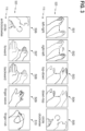
- gesture classes are conceivable. The particular choice of the set of gesture classes used for the gesture classification is not germane for the functioning of the techniques described herein. Nonetheless, hereinafter, a few examples will be given for possible gesture classes: TAB. 1: examples of various gesture classes that could be used in a respective predefined set to implement the gesture classification. These gesture classes define the gestures that can be recognized. Further details with respect to such gesture classes will be explained in connection with FIG. 3. (1) Swipe left to right (2) Swipe right to left (3) Swipe top to down (4) Swipe down to top (5) Circle clockwise (6) Circle anti-clockwise (7) Swipe back to front (8) Swipe front to back (9) Finger wave - wave single fingers (10) Finger rub - thumb sliding over fingers
- STO Smart Trunk Opener
- a kick-to-open motion is performed by the user using the foot.
- STO provides a flexible approach to the user by recognizing and classifying the hand movement or leg kick of the user and transmits the intention of the authorized user to open or close the trunk or door.
- Another example pertrains to a doorhandle presenter.
- the doorhandle upon a motion in the vicinity of the doorhandle, the doorhandle is moved from a retracted position to an exposed position in which it can be actuated.
- motion classification can be used to predict a motion class of a motion, e.g., a gesture.
- a motion class of a motion e.g., a gesture.
- the motion is not part of any one of the gesture classes - but, e.g., rather is part of a yet-to-be-defined motion class or corresponds to a general object movement not resembling a gesture. I.e., new motion classes can be identified.
- an HMI can be implemented. It is possible to control a machine. For instance, different actions could be triggered depending on the motion class of the recognized gesture.
- the HMI can facilitate control of a machine by a user.
- the techniques described herein are not limited to a particular use case of the HMI.
- Example use cases include: motion-controlled wearable and mobile devices, motion-controlled smart TVs, projectors, gesture-controlled smart homes and smart devices, automotive infotainment systems, augmented reality-virtual reality (AR-VR), feedback systems.
- Motion classification can replace alleviate the need for touch and clicks needed for HMI.
- gesture classification for sake of simplicity, reference will be made primarily to gesture classification; however, similar techniques may be readily applied to other types of motion, e.g., STO use cases.
- Various techniques disclosed herein employ a radar measurement of a scene including an object - e.g., a hand or finger or handheld object such as a stylus or beacon - to acquire data based on which the gesture classification can be implemented.
- an object e.g., a hand or finger or handheld object such as a stylus or beacon -
- radar chirps can be used to measure a position of one or more objects in a scene having extents of tens of centimeters or meters.
- a millimeter-wave radar sensor may be used to perform the radar measurement; the radar sensor operates as a frequency-modulated continuous-wave (FMCW) radar that includes a millimeter-wave radar sensor circuit, one or more transmitters, and one or more receivers.
- FMCW frequency-modulated continuous-wave
- a millimeter-wave radar sensor may transmit and receive signals in the 20 GHz to 122 GHz range. Alternatively, frequencies outside of this range, such as frequencies between 1 GHz and 20 GHz, or frequencies between 122 GHz and 300 GHz, may also be used.
- a radar sensor can transmit a plurality of radar pulses, such as chirps, towards a scene. This refers to a pulsed operation.
- the chirps are linear chirps, i.e., the instantaneous frequency of the chirps varies linearly with time.
- a Doppler frequency shift can be used to determine a velocity of the target.
- Measurement data provided by the radar sensor can thus indicate depth positions of multiple objects of a scene. It would also be possible that velocities are indicated.
- the radar sensor can output measurement frames.
- the measurement frames (sometimes also referred to as data frames or physical frames) include data samples over a certain sampling time for multiple radar pulses, specifically chirps. Slow time is incremented from chirp-to-chirp; fast time is incremented for subsequent samples. A channel dimension may be used that addresses different antennas.
- the radar sensor outputs a time sequence of measurement frames.
- gesture classification based on a radar measurements can have some advantages such as: invariant to illumination conditions; hand visibility occlusions; preserving privacy; capable of capturing subtle hand gesture motions.
- classification algorithms for determining a gesture class (or, more generally, a motion class) can be used.
- a heuristic-based classification algorithm that is manually parametrized could be used.
- ML machine-learning
- An example implementation of the ML algorithm is a neural network algorithm (hereinafter, simply neural network, NN).
- An NN generally includes a plurality of nodes that can be arranged in multiple layers. Nodes of given layer are connected with one or more nodes of a subsequent layer. Skip connections between non-adjacent layers are also possible. Generally, connections are also referred to as edges. The output of each node can be computed based on the values of each one of the one or more nodes connected to the input. Nonlinear calculations are possible. Different layers can perform different transformations such as, e.g., pooling, max-pooling, weighted or unweighted summing, non-linear activation, convolution, etc.
- the NN can include multiple hidden layers, arranged between an input layer and an output layer.
- An example NN is a convolutional NN (CNN). Here, 1-D or 2-D convolutional layers are used, together with other layers.
- Softmax classification layer For classification, it is possible to use a Softmax classification layer at the output.
- a softmax function is used and a cross-entropy loss is typically used during training.
- the calculation performed by the nodes are set by respective weights associated with the nodes.
- the weights can be determined in a training of the NN. For this, a numerical optimization can be used to set the weights.
- a loss function can be defined between an output of the NN in its current training can then minimize the loss function. For this, a gradient descent technique may be employed where weights are adjusted from back-to-front of the NN.
- the x-y-resolution of the input data and the output data may be decreased (increased) from layer to layer along the one or more encoder branches (decoder branches).
- the encoder branch provides a contraction of the input data
- the decoder branch provides an expansion.
- feature channels can increase and decrease along the one or more encoder branches and the one or more decoder branches, respectively.
- the one or more encoder branches and the one or more decoder branches are connected via a bottleneck.
- a particular implementation of the NN is an auto-encoder NN (AENN).
- the AENN as a general rule, includes an encoder branch and a decoder branch that are sequentially arranged and connected via a bottleneck. Away from the input layer and the output layer and specifically at the bottleneck, latent feature representations (feature embeddings) are obtained.
- the feature embedding can specify the presence or absence of certain features.
- the feature embedding thus can be seen as a compressed form of the input.
- the aim is to re-construct the input.
- a loss function can be defined during training of the AENN that penalizes differences between the input and the output. Accordingly, it is possible to train the AENN using unsupervised learning.
- the classification algorithm determines a gesture class of a gesture based on one or one-dimensional (1-D) time series of respective observables of a radar measurement associated with an object.
- the one or more 1-D time series can be the input to the classification algorithm or may be further pre-processed and then serve as the input to the classification algorithm.
- Each 1-D time series can specify the temporal evolution of the respective observable of the radar measurement.
- the observables can be quantified as real-valued numbers. For instance, it would be possible that one or more of the following observables are considered: range; absolute signal level; elevation angle; azimuthal angle.
- such 1-D time series corresponds to a compact representation of the radar measurement data.
- conventional pre-processing is based on information in the entire range-Doppler domain which - for close-range gesture recognition - includes mostly irrelevant information at larger ranges or higher Doppler shifts. Accordingly, by using one or more 1-D time series, a compact gesture classification algorithm operating based on low-dimensional input data is facilitated.
- Such gesture classification can be computational lightweight and, thus, can be executed on an embedded device, e.g., a smart phone or smart watch. Nonetheless, the reaction time of the gesture classification can be comparably low, e.g., in the sub-second regime. A high recognition rate has been observed.
- a time sequence of measurement frames of the radar measurement can be preprocessed to obtain the one or more 1-D time series of the observables of the radar measurement.
- a duration of each one of the one or more 1-D time series can be longer than the duration of each individual measurement frames.
- the physical frame duration of the measurement frames output by a radar sensor is in the order of tens of milliseconds (e.g., a typical repetition rate would be 30 Hz), which is much shorter than the typical duration of gestures to be classified, typically in the order of hundreds of milliseconds or even seconds.
- information from multiple subsequent measurement frames can be fused into the one or more 1-D time series so as to be able to coherently process respective time evolutions of the one or observables across the entire duration of the gesture using a classification algorithm.
- Fusing the radar data of multiple subsequent measurement frames into the one or more 1-D time series allows for accurate gesture classification, because the entire gesture duration can be coherently processed.
- FT Fourier transformation
- RDI range-Doppler image
- a pre-processing of the raw data output from the analog-to-digital converter (ADC) could include a two dimensional (2-D) FT of a measurement frame structured into fast-time dimension, slow-time dimension and antenna channels.
- the 2-D FT can be along fast-time and slow-time dimension. This yields the RDI.
- it would be possible to extract the range information e.g., for the strongest peak in the RDI, considering that the object performing the gesture provides the highest signal level.
- the absolute signal level can also be extracted for the strongest peak. For example, the index of the range bin with the highest absolute value and the index of the Doppler bin with the highest absolute value could be extracted. Alternatively within a certain area around the highest absolute value, the center of mass could be determined. The center of mass is then 2-D and the value of one dimension corresponds to the range value, the other to the Doppler value.
- a beamforming algorithm - e.g., the 2-D CAPON - can be used
- the 2-D CAPON also returns a 2-D matrix similar as the RDI. There the same extraction can be applied. Either using the index of the highest absolute value or center of mass.
- BPF complex-valued bandpass filter
- the BPF could be implemented by a low-pass filter.
- the BPF can have a linear phase response.
- the BPF can be applied to the data samples of each one of multiple subsequent measurement frames along the fast-time dimension.
- the BPF outputs complex-valued signals for the measurement frames. These complex-valued signals can then be used to determine the 1-D time series.
- Such techniques are based on the finding that, for near-field gesture sensing, it can be validly assumed that there is only a single target in the field of view and that the field of view is restricted to a certain range, e.g., 30 cm.
- a fine range resolution - e.g., based on RDI - may not be required, which comes with a high computational complexity.
- the BPF can be applied to the fast time dimension.
- the BPF acts as a limitation of the field of view, which means that all motions outside the region of interest are blended out.
- the signal is transformed to complex domain that allows access to the phase information.
- a computationally expensive FT is not required.
- RDI analysis is not required. This further reduces the computational burden and thus, facilitates, a short reaction time.
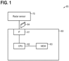
- FIG. 1 schematically illustrates a system 65.
- the system 65 includes a radar sensor 70 and a processing device 60.
- the processing device 60 can obtain measurement data 64 from the radar sensor 70.
- the processing device could be an embedded device, a smartphone, a smart watch, etc..
- a processor 62 - e.g., a general purpose processor (central processing unit, CPU), a field-programmable gated array (FPGA), an application-specific integrated circuit (ASIC) - can receive the measurement data 64 via an interface 61 and process the measurement data 64.
- the measurement data 64 could include a time sequence of measurement frames, each measurement frame including samples of an ADC converter.
- the processor 62 may load program code from a memory 63 and execute the program code.
- the processor 62 can then perform techniques as disclosed herein, e.g., pre-processing measurement data 64, predicting a motion class - e.g., a gesture class - based on the measurement data 64, controlling an HMI, etc..
- FIG. 2 illustrates aspects with respect to the radar sensor 70.
- the radar sensor 70 includes a processor 72 (labeled digital signal processor, DSP) that is coupled with a memory 73. Based on program code that is stored in the memory 73, the processor 72 can perform various functions with respect to transmitting radar pulses 86 using a transmit antenna 77 and a digital-to-analog converter (DAC) 75.
- DAC digital-to-analog converter
- the processor 72 can process raw data samples obtained from the ADC 76 to some larger or smaller degree. For instance, measurement frames (sometimes also referred to as data frames or physical frames) could be determined and output.
- the radar measurement can be implemented as a basic frequency-modulated continuous wave (FMCW) principle.
- a frequency chirp can be used to implement the radar pulse 86.
- a frequency of the chirp can be adjusted between a frequency range of 57 GHz to 64 GHz.
- the transmitted signal is backscattered and with a time delay corresponding to the distance of the reflecting object captured by all three receiving antennas.
- the received signal is then mixed with the transmitted signal and afterwards low pass filtered to obtain the intermediate signal. This signal is of significant lower frequency as the transmitted signal and therefore the sampling rate of the ADC 76 can be reduced accordingly.
- the ADC may work with a sampling frequency of 2 MHz and a 12-bit accuracy.
- a scene 80 includes multiple objects 81-83.
- the objects 81, 82 may correspond to background, whereas the object 83 could pertain to a hand of a user - accordingly, the object 83 may be referred to as target or target object.
- gestures performed by the hand can be recognized. Some gestures are illustrated in FIG. 3 .
- FIG. 3 schematically illustrates such gestures 501-510 and corresponding labels 115 of gesture classes 520, but other gestures are possible. According to the techniques described herein, it is possible to reliably and accurately classify the gestures 501-510. Details with respect to such gesture classification are explained in connection with FIG. 4 .
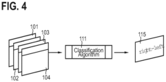
- FIG. 4 schematically illustrates a processing pipeline for implementing the gesture classification. For instance, such processing may be implemented by the processor 62 upon loading program code from the memory 63.
- a classification algorithm 111 obtains multiple 1-D time sequences 101-104 of respective observables of a radar measurement associated with a target object that performs a motion. Then, based on the multiple 1-D time series 101-104, the classification algorithm 111 determines a motion class of the motion performed by the object. A respective label 115 is output.
- TAB. 2 Various options for implementation of a ML classification algorithm. It is, in principle, possible to combine multiple different types of ML classification algorithms to obtain alternative predictions.
- the classification algorithm 111 could be implemented as a CNN.
- compact input data - e.g., the one or more 1-D time series or data derived therefrom - is used as an input
- a compact implementation of the CNN would be possible.
- an implementation that includes 5 or fewer convolutional layers performing 1-D convolutions only for processing each one of the one or more 1-D time series yields accurate results.
- a 3-layered 1-D CNN may be used.
- the first layer uses 32 filters with a kernel size of 64
- the second and third layer are using 64 kernels with a filter width of 32.
- an average pooling of size 2 can be performed and a rectified linear unit (ReLU) is applied as activation function.
- the convolutional block After the convolutional block, the tensor is flattened and fed into a fully connected layer with 32 output dimensions. Based on the output of this layer the classification is performed.
- an output of the CNN could be implemented by a fully-connected layer with a Softmax activation. This is only one option; a different scenario for the output layer is explained in example II below.
- a NN e.g., CNN
- Eucledian distance-based output It would also be possible to use an output of a NN, e.g., a CNN, that includes an output layer determining a Eucledian distance between an input sample vector and class weights associated with each one of respective candidate motion classes.
- Such techniques are based on the finding that, usually, a fully connected layer in a neural network is implemented by a matrix multiplication. Thus, the output is the scalar product of the input vector and the corresponding weight vector. If both vectors are normalized then the output is in fact the cosine similarity.
- the Euclidean distance is used as similarity measure. In this example, the last fully connected layer is replaced by a Euclidean distance layer, see T.
- the Euclidean distance layer outputs the Euclidean distance instead of the scalar product between input vector and each weight vector.
- the weight vectors can be interpreted as the centers of their corresponding gesture class. During training, the centers are shifting to optimal positions in the feature space. Unlike as proposed in T.
- a recurrent architecture such as a long-short-term-memory (LSTM) architecture can be used.
- the LSTM architecture includes multiple units, each composed of a respective cell, input data, output data and forget gate.
- the cell can, respectively, be implemented by a respective CNN. Thereby, time-dependencies of the one or more 1-D time series can be evaluated using the recurrent structure of the LSTM architecture.
- the feature embedding can be used to determine the motion class. For instance, the position of the feature embedding for a given prediction can be compared with multiple predefined regions in the feature space. The different predefined regions can be obtained from training and can be respectively associated with different candidate motion classes.
- a count of four 1-D time series 101-104 is illustrated (e.g., range, absolute signal, azimuthal angle, elevation angle), as a general rule, fewer or more or other 1-D time series may be used as the input to the classification algorithm 111.
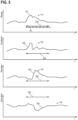
- FIG. 5 schematically illustrates aspects with respect to a 1-D time series 101.
- the time series 101 is indicative of a range 251 of the object.
- the range 251 of the object changes during a gesture duration 250.
- a sequence of measurement frames 45 is obtained from the radar unit during the gesture duration and fused into the 1-Dtime series 251.
- FIG. 5 also schematically illustrates aspects with respect to a 1-D time series 102.
- the time series 102 is indicative of the signal amplitude 252 of the signal contributions associated with the object.
- the signal amplitude 252 typically depends on the range 251 of the object, as well as on the radar cross-section of the object.
- FIG. 5 further schematically illustrates aspects with respect to a 1-D time series 103.
- the time series 103 is indicative of the elevation angle 253 of the object.
- FIG. 5 still further schematically illustrates aspects with respect to a 1-D time series 104.
- the time series 104 is indicative of the azimuthal angle 254 of the object.
- FIG. 6 is a flowchart of a method according to various examples. The method can be executed by at least one processor, e.g., upon loading program code from a memory. For instances, the method of FIG. 6 could be executed by the processor 72 and/or the processor 62 (cf. FIGs. 1 and 2 ). The method of FIG. 6 pertains to operation and maintenance of the classification algorithm 111.
- a training of the classification algorithm 111 is implemented.
- values of multiple parameters of the classification algorithm 111 are set.
- each training set including a respective time sequence of mesaurement frames and an associated ground-truth label that is indicative of a respective candidate motion class selected from a plurality of candidate motion classes.
- the ground-truth label is indicative of the motion class of the motion executed by the object in the radar measurement data of the respective training set.
- the ground-truth label can be manually determined based on prior knowledge.
- the training can be based one or more losses defined by a respective loss function. Each loss can correspond to a respective contribution of the loss function. Each loss can be determined based on a difference between a prediction of the NN in its current training state and a corresponding ground truth. The ground truth can be obtained from the ground-truth label or the training input, e.g., for an AENN. Different losses use different metrics to quantify such difference and/or use different predictions and/or inputs.
- An iterative optimization can be implemented.
- multiple sets can be used to adjust the weights in multiple iterations.
- Each iteration can include a backpropagation training algorithm to adjust the weights starting from an output layer of the NN towards an input layer.
- the particular training process and loss function can depend on the choice of the NN, cf. TAB. 2.
- a cross entropy loss can be used as conventionally done for softmax activation.
- the objective is to minimize the squared Euclidean distance to the own class center m p - see Eq. (1) - and to maximize the Euclidean distances to all other or negative class centers m n - see Eq. (2).
- the first loss according to Eq. 1 penalizes the Euclidean distance to the class weights of the respective candidate motion class indicated by a ground-truth label (higher reward for smaller Euclidian distances); while the second loss according to Eq. 2 rewards the Euclidian distance (higher reward for larger distances) to the class weights of other candidate motion classes not indicated by that ground-truth label.
- Such a disentangled intra class and inter class loss leads to more discriminative class clusters than maximizing only the intra class score as it is the case, e.g., for the cross-entropy loss.
- the class centers are regularized in a way that they are orthogonal to each other. This is achieved as defined in (3), where the means square error of the vector normalized and squared mean matrix M and the identity matrix I is calculated. This leads to an orthogonal signal subspace spanned by the class center vectors. Orthogonality is a valuable characteristic that can be used for detecting and rejection non-gesture motions or more generally spoken out of distribution samples.
- L intra ⁇ m p ⁇ x ⁇ 2 2
- L inter ⁇ n ⁇ N ⁇ m n ⁇ x ⁇ 2 2
- R MSE I ⁇ MM T
- L ⁇ 0 L intra + ⁇ 1 L inter + ⁇ 2 R
- triplet loss is a metric learning technique that pulls together in feature space samples of the same class and pushes away, in feature space, dissimilar samples, i.e., samples belonging to different classes. Therefore, well-defined clusters are formed in the feature space and can be used as predefined region to which the feature position of the feature embedding in a prediction is compared. For instance, to determine the predefined region, the mean embedding vector of all training samples for each class can be determined. The predefined region can be centered at the mean embedding vector.
- the triplet loss is generally known from . Ge, W. Huang, D. Dong, and M. R. Scott. 2018. Deep Metric Learning with Hierarchical Triplet Loss. CoRR abs/1810.06951 (2016). arXiv:1810.06951 .
- the idea of the triplet loss is to feed three samples (i.e., three training sets of 1-D time series101-104) into AENN 111.
- the first training set 109 is the anchor
- the second training set 109 is a random sample of the same gesture class
- the third training set 109 is a random sample of another gesture class.
- inference can be implemented at box 3010.
- a prediction of a gesture class of a gesture of a scene can be made without relying on corresponding ground truth.
- the weights of the NN as determined in the training of box 3005 are used.
- FIG. 7 schematically illustrates aspects with respect to an implementation of the classification algorithm 111 as AENN.
- the AENN includes an encoder branch 141 and a decoder branch 142.
- the decoder branch 142 operates on a feature embedding 149 representing latent features of the 1-D time series 101-104 provided as input to the encoder branch 141.
- the decoder branch 142 may not be required during inference at box 3010 (cf. FIG. 5 ), but rather only during training at box 3005 to calculate a respective reconstruction loss.
- the decoder branch 142 outputs reconstructions 181-184 of the positional time spectrograms 101-104.
- the gesture class 520 is predicted based on the feature embedding 149.
- the label 115 - e.g., "L-R Swipe" - identifying the gesture class 520 is thus extracted from the feature embedding 149. This is explained in detail next.
- each data point 201-204 in latent feature space 200. I.e., each data point 201-204 describes a respective observation of a respective gesture.
- These data points 201-204 equate to or more generally are derived from the respective feature embedding 149.
- predefined regions 211-213 defined in the feature space 200 there can be predefined regions 211-213 defined in the feature space 200 and it can be checked whether the data points 201-204 are within one of these predefined regions 211-213.
- These predefined regions 211-213 can be obtained from the training of the AENN, e.g., using a triplet loss as explained above in box 3010. They can be defined by the class average for all training sets of a given gesture class.
- FIG. 6 Also illustrated in FIG. 6 is a scenario in which multiple data points 204 form a cluster 214 that is offset from any one of the predefined regions 211-213. It would be possible to use such cluster 214 to define a new gesture class.
- FIG. 8 schematically illustrates aspects with respect to the measurement data 64.
- FIG. 8 schematically illustrates a structure of raw data in form of a measurement frame 45.
- a measurement frame 45 is defined by arranging data samples 49 obtained as raw data from the ADC (as explained in connection with FIG. 2 ) with respect to a fast-time dimension 42 and a slow-time dimension 41 ( FIG. 9 is a schematic illustrative drawing; instead of sampling the received signal directly, the ADC samples a processed signal obtained from mixing the transmitted signal with the received signal; this is generally referred to as a Frequency-Modulated Continuous Wave, FMCW, radar measurement).
- a position along the fast time dimension 42 is incremented for each subsequent readout from the ADC (this is illustrated in the circular inset in FIG. 9 ), whereas a position along the slow time dimension 41 is incremented with respect to subsequent radar chirps 48.
- antenna or channel dimension 43 (not illustrated in FIG. 9 ), which provides angular resolution based on phase shifts of the incident electromagnetic waves between adjacent antennas. For instance, in FIG. 2 , an example with three receive channels has been discussed.
- the duration of the measurement frames 45 is typically defined by a measurement protocol.
- the measurement protocol can be configured to use 32 chirps within a measurement frame 45.
- the frame repetition frequency may be set to 30 frames per second.
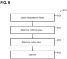
- FIG. 9 is a flowchart of a method according to various examples.
- the method of FIG. 9 may be executed by a processing device such as the processing device 60 of the system 65 illustrated in FIG. 1 .
- the method may be executed by the processor 62 upon loading and executing program code from the memory 63.
- FIG. 9 illustrates aspects with repsect to inference. I.e., FIG. 9 can implement box 3010.
- FIG. 9 thus corresponds to determining a motion class or, more accurately, a prediction of the motion class without ground truth.
- a time sequence of measurement frames of a radar measurement of a scene including an object is obtained.
- the time sequence may be obtained from the radar unit, e.g., from a digital signal processor coupled to an ADC.
- the time sequence could also be loaded from a memory.
- a complex-valued BPF with linear phase response may be applied to the data samples of each one of the multiple subsequent measurement frames along the fast-time dimension.
- complex-valued signals are obtained for the measurement frames.
- These complex-valued signals are, accordingly, resolved along the slow-time dimension and along the channel dimension. It is then possible to determine the one or more time series based on the complex-valued signals.
- a motion class of a motion performed by the object is determined, using a classification algorithm and based on the one or more 1-D time series that are determined at box 3110.
- one or more use cases / applications may be facilitated by the motion class of the motion that it is determined at box 3115.
- an HMI may be controlled.
- a car trunk may be opened.
- Proximity sensing-based control of, e.g., a door-handle presenter in a car may be operated.
- FIG. 10 illustrates the signal processing implementing boxes 3105 and 3110 in an example scenario.
- the time sequence of measurement frames is obtained. This corresponds to box 3005.
- a motion detection or specifically a gesture detection it is optionally possible to perform a motion detection or specifically a gesture detection.
- a motion class may not be resolved, it is possible to determine a gesture duration 250. Measurement frames outside of the gesture duration 250 can be discarded. For instance, a signal change rate could be observed for such detection.
- the measurement data provided by the radar unit is real valued.
- the phase of the signal is needed.
- a FT is applied along fast time dimension.
- the frequencies within a chirp provide the range information of the received signal.
- the signal is complex valued and hence angle or Doppler estimation can be done in a second step.
- the FT along fast-time dimension divides the signal into N range bins. These can be evaluated to obtain angle and range information, etc.. (This processing is not shown in FIG. 10 ).
- the filter is lightweight and fast.
- the signal Since the signal is static within a chirp, no convolution per se is performed but the fast-time samples can be multiplied / convolved with the complex-valued sinc BPF.
- the signal within a measurement frame - after applying the BPF - is complex valued and 1-D.
- the filter parameters f c and b may be predefined.
- f c may be chosen to be 0.25 normalized frequency and b is set to 0.5 normalized frequency.
- the center frequency and the bandwidth can define a cut-off frequency.
- the cut-off frequency of the BPF can be set to a frequency associated with a range of less than 50 cm, for typical use case scenarios.
- a coherent integration (box 5205) over all receiving channels, i.e., across the channel dimension - is performed.
- the absolute signal becomes 1-D a[k] and the phase signal is two dimensional ⁇ [ r , k ] , where r is the receiving channel index and k the time index.
- the absolute signal a[k] can serve as or as basis of the 1-D time series 102 (cf. FIG. 5 ), e.g., when concatenated across multiple sequential frames.
- the idle time between subsequent measurement frames 45 can cause a random phase offset between first sampling point in the frame f and the last sample in the preceding frame f-1 .
- phase correction factor is applied.
- the phase correction factor can be determined based on the phase offset, i.e., the difference of the phase signal of Eq. 10 is used.
- the corresponding values in the phase difference signal ⁇ ⁇ may be set to the mean of the preceding and succeeding value.
- the phase correction factor can be determined based on, specifically scaled by the absolute value before integrating. This is, in particular, helpful for the determination of the range time series 101, because here - different to the determination of the angular time series 103, 104 - the phase change over time is considered.
- the phase correction factor may be set to zero where the absolute value of the complex-valued signals (Eq. 9) is below a certain threshold before integration, to thereby avoid summing up noise. Subsequently, the reconstructed phase signal can be integrated over the receiving channels.
- Such scaling of the phase correction factor based on the absolute signal level is illustrated in box 5310.
- the time series 101-104 can be determined.
- the time series 102 indicative of the absolute signal has been already discussed above and is obtained by integrating along the channel dimension (box 5205).
- time series 103 and 104 indicative of angular positions of the object 83 are discussed.
- the phase difference between receiving channels indicates the angle of arrival.
- both, the azimuth and elevation signals according to Eqs. 14 and 15 may be integrated over time (boxes 5110, 5160), i.e., along the slow-dime dimension. This yields time integrated phase differences.
- the slope of the time-integrated phase differences then represents the angle of arrival. The steeper it is the larger is the integrated phase offset, which means that the target is at the border of the field of view.
- the range time series 101 is determined by determining the phase gradient of the complex-valued signals along the slow-time dimension (box 5305). This yields the velocity. Thenan integration over time (box 5315) yields the range. At box 5320, a coherent integration across channel dimension is implemented, similar to box 5205.
- the radar signal is represented as four 1-D time series 101-104, namely the relative range, the integrated azimuth phase offset, the integrated elevation phase offset and the absolute value.
- the signal was transformed from a 2-D and frame wise signal into a 1-D frame-continuous signal.
- a continuous 1-D convolution with individual kernel sizes can be applied in a convolutional layer without being restricted to the measurement frames 45.
- the approach makes use of the fact that only a single target is within the field of view. In conventional processing, an FT resolves the entire range-Doppler domain in the RDI, however, when there is only a single target, most of the range Doppler bins will just be zero. With the presented data representation, only the target signal is captured.
- the SNR of the phase azimuth and elevation signal can be significantly improved.
- the target with the highest radar cross section which is usually the palm of the hand for gesture sensing, leads to the lowest frequency part in the phase signal. Finger movements introduce phase offsets on top of this. Thus, by band pass filtering the macro motion of the hand and the micro motions of the fingers can be independently analyzed.
- FIG. 11 illustrates aspects with respect to the signal processing of the complex-valued BPF 980. Specifically, FIG. 11 illustrates a scenario where one or more filter parameters of the complex-value BPF are adaptive.
- Such adaptive filtering is based on the finding that the target object may change its radial position or its radial velocity relative to the radar unit. Hence, it is helpful to adjust the the one or more filter parameters such as the filter frequency to follow the object's movements.
- FIG. 11 An example implementation of associated processing is illustrated in FIG. 11 .
- the processing of FIG. 11 accordingly, can implement box 5015 of FIG. 10 and can be part of box 3110 of FIG. 9 .
- the channel dimension is omitted.
- the respective processing can be independently extended across multiple channel dimensions.
- FIG. 11 schematically illustates a 2-D BPF.
- a first branch 6001 is used to track the target position along the slow-time dimension (Doppler position); while a second branch 6002 is used to track the target position along the fast-time dimension (range position).
- the center frequncy for slow-time dimension ( f ST ) is adapted; while in branch 6002 the center frequency for fast-time dimension ( f FT ) is adapted.
- Branch 6001 employs a 2-D convolution at 6014, between the measurement frame 45 and a respective filter kernel defined at box 6010.
- Branch 6002 also employs a 2-D convoltuion at 6114, between the measurement frame 45 and a respective filter kernel defined at box 6110.
- both branches 6001, 6002 employ a 2-D filtering.
- the filter kernels differ in dimensionality. This helps to resolve the signal along the particular dimension 41, 42 for which the respective center frequency is to be updated. The other dimension is collapsed.
- the 1-D BPF filter of Eq. 7 can be seen as an extrem case of the 2-D BPF filter in branch 6001.
- the 1-D BPF of Eq. 7 corresponds to a degenerated 2-D BPF which has a filter dimension of 1 in slow-time dimension 41.
- the Doppler selectivity is lost.
- the Doppler area selectivity makes sense if there are two targets moving with different speeds, which is motivated in connection with FIG. 12 .
- FIG. 12 illustrates range-Doppler positions of two targets 901, 902.
- the two targets 901, 902 are at a similar range, but move in opposite direction.
- a 1-D BPF filter according to Eq. 7, one can select the signal within a certain range area 911 (dashed line in FIG. 12 ). After filtering, the signal still contains a mixture of both targets 901, 902.
- the range position or fast time center frequency
- the target of interest e.g., target 901.
- a 2-D sinc filter cf. FIG. 11
- the targets 901, 902 can then be separated.
- phase unwrapping it is possible to determine the range position or fast-time center frequency of the target 901 of interest. This information will then be used to update the fast time center frequency of the 2-D BPF filter.
- FIG. 11 illustrates a measurement frame 45 that is input into the processing pipeline, at box 6005.
- the measurement frame 45 has a size of 64 along fast-time dimension 42 and a size of 32 along slow-time dimension 41.
- the filter length along the fast-time dimension 41 equals the number of samples per chirp (here: 64) and is smaller than the number of chirps along slow-time dimension (here: 17, which is smaller than 32).
- the raw signal of the current measurement frame 45 can be convolved , in branch 6002 at the 2-D convolution 6014, with this filter kernel without using zero padding along the fast-time dimension.
- the complex signal 6099 obtained for branch 6002 only includes a single value along fast-time dimension 42.
- this complex-valued signal is within the range frequency region defined by the slow-time center frequency f ST and the fast-time f FT center frequency defined by the 2-D convolution of box 6014.
- the output is a 1-D slow-time complex-valued signal 6099, that is on the one hand used to update the slow-time center frequency (feedback branch 6015) and on the other hand it is used for further processing (cf. FIG. 10 ).
- the complex-valued signal 6099 is used to determine the time series 101-104 (cf. FIG. 10 ; not shown in FIG. 11 ).
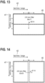
- the 2-D convolution 6014 of branch 6001 is illustrated in FIG. 13 .
- the vertical arrow illustrates the convolution 6014.
- the output dimension after the convoltuion can be calculated as: "singal length - filter length + 1".
- the center frequencies are iteratively adapted for subsequent measurement frames 45, for each branch 6001, 6002.
- This iterative nature of the adaption is illustrated by the box 6035 where a respective delay path is indicated.
- Phase unwrapping is achieved by box 6025.
- Phase differences larger than Pi are corrected by subtracting 2Pi; phase differences smaller than -Pi are corrected by adding 2Pi.
- the new center frequency is determined based on a phase gradient that is determined in box 6030.
- branch 6002 also corresponds to the processing in branch 6001, i.e., box 6125 corresponds to box 6025, box 6130 corresponds to box 6030, box 6135 corresponds to box 6035, and box 6110 corresponds to box 6010.
- the fast-time center frequency f FT in branch 6002 as well as the slow-time center frequency f ST in branch 6001 are adapted according to the current observed signal. This is done for each dimension independently using the two branches 6001, 6002, but in the same manner.
- the 2-D BPF is tracking the target in range-Doppler domain by completely operating on the raw time domain data.
- the gesture classification is based on a radar measurement.
- a ML algorithm can be used.
- One or more time series of range, angular position and/or absolute signal level can be used as input, concatenated across multiple measurement frames.
- the signal is represented as multiple 1-D time series, it is possible to use a 1-D CNN as the classification algorithm, instead of a 2-D CNN as it is the case for interpreting the FT pre-processed feature maps.
- the classification algorithm and the computational complexity of the classification algorithm can be significantly reduced. Further, no specialized digital signal processing hardware is used for pre-processing the radar data.
- the bandwidth of the transmit chirps can be lowered below 500MHz, which makes the system FCC compliant.
- EXAMPLE 1 A computer-implemented method, the method comprising:
- each measurement frame (45) of the time sequence of measurement frames (45) comprises data samples along a fast-time dimension (42), a slow-time dimension (41), and a channel dimension (43), a slow time of the slow-time dimension (41) being incremented with respect to adjacent radar chirps of the radar measurement, a fast time of the fast-time dimension (42) being incremented with respect to adjacent data samples, a channel of the channel dimension (43) being incremented for different receiver antennas (78-1, 78-2, 78-3) used for the radar measurement, wherein the method further comprising:
- EXAMPLE 3 The computer-implemented method of EXAMPLE 2, further comprising:
- EXAMPLE 4 The computer-implemented method of EXAMPLE 2 or 3, further comprising:
- EXAMPLE 5 The computer-implemented method of any one of EXAMPLEs 2 to 4, wherein at least one second 1-D time series (103, 104) of the one or more 1-D time series (101, 102, 103, 104) indicative of at least one angular position (253, 254) of the object (83) is determined based on phase differences (5105, 5155) of the complex-valued signals (6099) between respective pairs of the channels (78-1, 78-2, 78-3) of the channel dimension (43).
- EXAMPLE 6 The computer-implemented method of EXAMPLE 5, further comprising:
- EXAMPLE 7 The computer-implemented method of any one of EXAMPLEs 2 to 6, wherein a third 1-D time series (101) of the one or more 1-D time series (101, 102, 103, 104) indicative of a range position (251) of the object (83) is determined based on a phase gradient (5305) of the complex-valued signals (6099) along the slow-time dimension (41) and by respectively integrating (5320) the phase gradient of the complex-valued signals (6099) across the channel dimension (43).
- a third 1-D time series (101) of the one or more 1-D time series (101, 102, 103, 104) indicative of a range position (251) of the object (83) is determined based on a phase gradient (5305) of the complex-valued signals (6099) along the slow-time dimension (41) and by respectively integrating (5320) the phase gradient of the complex-valued signals (6099) across the channel dimension (43).
- EXAMPLE 8 The computer-implemented method of any one of EXAMPLEs 2 to 7, further comprising:
- EXAMPLE 9 The computer-implemented method of EXAMPLE 8, wherein said concatenating (5020) further comprises:
- EXAMPLE 10 The computer-implemented method of EXAMPLE 9, wherein the phase correction factor is determined based on the phase offsets.
- EXAMPLE 11 The computer-implemented method of EXAMPLE 9 or 10, wherein the phase correction factor is determined based on an absolute value of the respective complex-valued signals (6099).
- EXAMPLE 12 The computer-implemented method of any one of EXAMPLEs 2 to 11, wherein a cut-off frequency of the complex-valued bandpass filter is at a frequency associated with a range of less than 50 cm.
- EXAMPLE 13 The computer-implemented method of any one of EXAMPLEs 2 to 12, wherein the complex-valued bandpass filter further filters along the slow-time dimension (41).
- EXAMPLE 14 The computer-implemented method of EXAMPLE 13,
- EXAMPLE 15 The computer-implemented method of any one of the preceding EXAMPLEs,
- EXAMPLE 16 The computer-implemented method of any one of the preceding EXAMPLEs,
- EXAMPLE 17 The computer-implemented method of any one of the preceding EXAMPLEs,
- EXAMPLE 18 The computer-implemented method of any one of the preceding EXAMPLEs,
- a computer-implemented method of training (3005) a convolutional neural network algorithm (111) for predicting a gesture class (520) of a motion performed by an object (83) based on a time sequence of measurement frames (45) of a radar measurement of a scene (80) comprising the object (83), the convolutional neural network algorithm (111) comprising an output layer determining an Euclidean distance between an input sample vector and class weights of each one of a plurality of candidate motion classes, wherein the method comprises:
- a device (60) comprising a processor (62) configured to:
- EXAMPLE 21 The device (60) of EXAMPLE 20, wherein the processor is configured to perform the method of any one of EXAMPLEs 1 to 18.
- a device (60) comprising a processor (62) for training (3005) a convolutional neural network algorithm (111) for predicting a gesture class (520) of a motion performed by an object (83) based on a time sequence of measurement frames (45) of a radar measurement of a scene (80) comprising the object (83), the convolutional neural network algorithm (111) comprising an output layer determining an Euclidean distance between an input sample vector and class weights of each one of a plurality of candidate motion classes, wherein the processor is configured to:
- the possible gesture classification is not limited to just hand gesture but virtually any form of gesture feedback such as body pose or facial expressions. General motions may be detected.
Landscapes
- Engineering & Computer Science (AREA)
- Radar, Positioning & Navigation (AREA)
- Remote Sensing (AREA)
- Physics & Mathematics (AREA)
- General Physics & Mathematics (AREA)
- Computer Networks & Wireless Communication (AREA)
- Theoretical Computer Science (AREA)
- Evolutionary Computation (AREA)
- Multimedia (AREA)
- Health & Medical Sciences (AREA)
- General Health & Medical Sciences (AREA)
- Artificial Intelligence (AREA)
- Computer Vision & Pattern Recognition (AREA)
- Human Computer Interaction (AREA)
- General Engineering & Computer Science (AREA)
- Computing Systems (AREA)
- Medical Informatics (AREA)
- Software Systems (AREA)
- Databases & Information Systems (AREA)
- Mathematical Physics (AREA)
- Psychiatry (AREA)
- Social Psychology (AREA)
- Radar Systems Or Details Thereof (AREA)
Priority Applications (3)
| Application Number | Priority Date | Filing Date | Title |
|---|---|---|---|
| EP21201047.4A EP4163666A1 (de) | 2021-10-05 | 2021-10-05 | Radarbasierte bewegungsklassifizierung unter verwendung einer oder mehrerer zeitreihen |
| US17/935,765 US12529777B2 (en) | 2021-10-05 | 2022-09-27 | Radar-based motion classification using one or more time series |
| CN202211216809.9A CN115951320A (zh) | 2021-10-05 | 2022-09-30 | 使用一个或多个时间序列的基于雷达的运动分类 |
Applications Claiming Priority (1)
| Application Number | Priority Date | Filing Date | Title |
|---|---|---|---|
| EP21201047.4A EP4163666A1 (de) | 2021-10-05 | 2021-10-05 | Radarbasierte bewegungsklassifizierung unter verwendung einer oder mehrerer zeitreihen |
Publications (1)
| Publication Number | Publication Date |
|---|---|
| EP4163666A1 true EP4163666A1 (de) | 2023-04-12 |
Family
ID=78080193
Family Applications (1)
| Application Number | Title | Priority Date | Filing Date |
|---|---|---|---|
| EP21201047.4A Pending EP4163666A1 (de) | 2021-10-05 | 2021-10-05 | Radarbasierte bewegungsklassifizierung unter verwendung einer oder mehrerer zeitreihen |
Country Status (3)
| Country | Link |
|---|---|
| US (1) | US12529777B2 (de) |
| EP (1) | EP4163666A1 (de) |
| CN (1) | CN115951320A (de) |
Families Citing this family (5)
| Publication number | Priority date | Publication date | Assignee | Title |
|---|---|---|---|---|
| EP4320554A1 (de) * | 2021-04-09 | 2024-02-14 | Google LLC | Verwendung eines maschinell erlernten moduls zur radarbasierten gestenerkennung in einer umgebungscomputerumgebung |
| EP4202475B1 (de) * | 2021-12-23 | 2024-05-01 | GM Cruise Holdings LLC | Radarstrahlformung mittels latenter raumcodierung |
| US12474782B2 (en) | 2023-05-01 | 2025-11-18 | Samsung Electronics Co., Ltd. | Burst-based non-gesture rejection in a micro-gesture recognition system |
| CN116908808B (zh) * | 2023-09-13 | 2023-12-01 | 南京国睿防务系统有限公司 | 一种基于rtn的高分辨一维像目标识别方法 |
| EP4733961A1 (de) * | 2024-10-28 | 2026-04-29 | Bayerische Motoren Werke Aktiengesellschaft | Verfahren zur verbesserung einer öffnung einer klappe eines fahrzeugs, vorrichtung, fahrzeug und computerprogramm |
Citations (1)
| Publication number | Priority date | Publication date | Assignee | Title |
|---|---|---|---|---|
| US20190243464A1 (en) * | 2015-04-30 | 2019-08-08 | Google Llc | Type-Agnostic RF Signal Representations |
Family Cites Families (36)
| Publication number | Priority date | Publication date | Assignee | Title |
|---|---|---|---|---|
| DE2902039A1 (de) * | 1979-01-19 | 1980-07-24 | Siemens Ag | Gegen anti-radar-flugkoerper geschuetztes ueberwachungsradarsystem |
| FR2478822A1 (fr) * | 1980-03-18 | 1981-09-25 | Thomson Csf | Systeme de detection active au moyen d'emissions multiples simultanees |
| US4804962A (en) * | 1983-08-04 | 1989-02-14 | Diamond Devices, Inc. | Clutter elimination radar |
| US4851848A (en) * | 1988-02-01 | 1989-07-25 | The United States Of America As Represented By The Secretary Of The Navy | Frequency agile synthetic aperture radar |
| US5093649A (en) * | 1990-08-28 | 1992-03-03 | The Boeing Company | Bessel beam radar system using sequential spatial modulation |
| GB0701869D0 (en) * | 2007-01-31 | 2007-03-14 | Cambridge Consultants | Adaptive radar |
| DE102007031020B3 (de) * | 2007-07-04 | 2008-12-24 | Deutsches Zentrum für Luft- und Raumfahrt e.V. | Verfahren zur Verarbeitung von TOPS(Terrain Observation by Progressive Scan)-SAR(Synthetic Aperture Radar)-Rohdaten und Verwendung des Verfahrens |
| US7898468B2 (en) * | 2008-02-14 | 2011-03-01 | Raytheon Company | Radar imaging of buildings using model-based focusing and data-based focusing |
| US11163050B2 (en) * | 2013-08-09 | 2021-11-02 | The Board Of Trustees Of The Leland Stanford Junior University | Backscatter estimation using progressive self interference cancellation |
| GB2517710A (en) * | 2013-08-28 | 2015-03-04 | Aveillant Ltd | Radar system and associated apparatus and methods |
| US9291659B2 (en) * | 2013-12-19 | 2016-03-22 | Ford Global Technologies, Llc | Antenna blockage detection |
| US20150253419A1 (en) * | 2014-03-05 | 2015-09-10 | Delphi Technologies, Inc. | Mimo antenna with improved grating lobe characteristics |
| US9568600B2 (en) * | 2014-03-05 | 2017-02-14 | Delphi Technologies, Inc. | MIMO antenna with elevation detection |
| WO2015168700A1 (en) * | 2014-05-02 | 2015-11-05 | The Board Of Trustees Of The Leland Stanford Junior University | Method and apparatus for tracing motion using radio frequency signals |
| US10168420B1 (en) * | 2014-07-15 | 2019-01-01 | Herbert U. Fluhler | Nonlinear interferometric imaging sensor |
| US9784820B2 (en) * | 2014-09-19 | 2017-10-10 | Delphi Technologies, Inc. | Radar system with phase based multi-target detection |
| US9952313B2 (en) * | 2014-09-19 | 2018-04-24 | The Boeing Company | Phase calibration of a stepped-chirp signal for a synthetic aperture radar |
| US10006991B2 (en) * | 2015-02-11 | 2018-06-26 | Honeywell International Inc. | Velocity and attitude estimation using an interferometric radar altimeter |
| US9599702B1 (en) * | 2016-04-25 | 2017-03-21 | Uhnder, Inc. | On-demand multi-scan micro doppler for vehicle |
| US9575160B1 (en) * | 2016-04-25 | 2017-02-21 | Uhnder, Inc. | Vehicular radar sensing system utilizing high rate true random number generator |
| WO2018069120A1 (en) * | 2016-10-13 | 2018-04-19 | Iee International Electronics & Engineering S.A. | Method and system for obtaining angle-doppler signatures in mimo radars |
| US10576328B2 (en) * | 2018-02-06 | 2020-03-03 | Infineon Technologies Ag | System and method for contactless sensing on a treadmill |
| JP7044972B2 (ja) * | 2018-07-04 | 2022-03-31 | 日本電信電話株式会社 | 無線通信装置及び無線通信方法 |
| US11585889B2 (en) * | 2018-07-25 | 2023-02-21 | Qualcomm Incorporated | Methods for radar coexistence |
| DE102018214961A1 (de) * | 2018-09-04 | 2020-03-05 | Robert Bosch Gmbh | Verfahren zur Erkennung von Winkelmessfehlern bei einem Radarsensor |
| JP7108929B2 (ja) * | 2018-09-25 | 2022-07-29 | パナソニックIpマネジメント株式会社 | レーダ装置及び物標判定方法 |
| US11313950B2 (en) * | 2019-01-15 | 2022-04-26 | Image Sensing Systems, Inc. | Machine learning based highway radar vehicle classification across multiple lanes and speeds |
| US11822007B2 (en) * | 2019-02-14 | 2023-11-21 | Elta Systems Ltd. | System and method for identification of an airborne object |
| US11754704B2 (en) * | 2019-03-29 | 2023-09-12 | Nec Corporation | Synthetic-aperture-radar image processing device and image processing method |
| US10404387B1 (en) * | 2019-05-15 | 2019-09-03 | Cognitive Systems Corp. | Determining motion zones in a space traversed by wireless signals |
| US10855328B1 (en) * | 2019-07-03 | 2020-12-01 | Qualcomm Incorporated | Interference suppression for multi-radar coexistence |
| US11275928B2 (en) * | 2019-12-12 | 2022-03-15 | Realnetworks, Inc. | Methods and systems for facial recognition using motion vector trained model |
| US11567580B2 (en) * | 2020-01-29 | 2023-01-31 | Samsung Electronics Co., Ltd. | Adaptive thresholding and noise reduction for radar data |
| US11467254B2 (en) * | 2020-02-27 | 2022-10-11 | Samsung Electronics Co., Ltd. | Method and apparatus of radar-based activity detection |
| US11774553B2 (en) * | 2020-06-18 | 2023-10-03 | Infineon Technologies Ag | Parametric CNN for radar processing |
| WO2022139783A1 (en) * | 2020-12-21 | 2022-06-30 | Intel Corporation | High end imaging radar |
-
2021
- 2021-10-05 EP EP21201047.4A patent/EP4163666A1/de active Pending
-
2022
- 2022-09-27 US US17/935,765 patent/US12529777B2/en active Active
- 2022-09-30 CN CN202211216809.9A patent/CN115951320A/zh active Pending
Patent Citations (1)
| Publication number | Priority date | Publication date | Assignee | Title |
|---|---|---|---|---|
| US20190243464A1 (en) * | 2015-04-30 | 2019-08-08 | Google Llc | Type-Agnostic RF Signal Representations |
Non-Patent Citations (5)
| Title |
|---|
| DUBEY ANAND ET AL: "A Bayesian Framework for Integrated Deep Metric Learning and Tracking of Vulnerable Road Users Using Automotive Radars", IEEE ACCESS, IEEE, USA, vol. 9, 5 May 2021 (2021-05-05), pages 68758 - 68777, XP011854438, DOI: 10.1109/ACCESS.2021.3077690 * |
| S. RAUTARAYA. AGRAWAL: "Vision based hand gesture classification for human computer interaction: a survey", ARTIFICIAL INTELLIGENCE REVIEW, vol. 43, no. 1, 2015, pages 1 - 54, Retrieved from the Internet <URL:https://doi.org/l0.l007/s10462-012-9356-9.> |
| STADELMAYER THOMAS ET AL: "Data-Driven Radar Processing Using a Parametric Convolutional Neural Network for Human Activity Classification", IEEE SENSORS JOURNAL, IEEE, USA, vol. 21, no. 17, 24 June 2021 (2021-06-24), pages 19529 - 19540, XP011875483, ISSN: 1530-437X, [retrieved on 20210830], DOI: 10.1109/JSEN.2021.3092002 * |
| STADELMAYER THOMAS ET AL: "Improved Target Detection and Feature Extraction using a Complex-Valued Adaptive Sine Filter on Radar Time Domain Data", 2021 29TH EUROPEAN SIGNAL PROCESSING CONFERENCE (EUSIPCO), EURASIP, 23 August 2021 (2021-08-23), pages 1745 - 1749, XP034038335, DOI: 10.23919/EUSIPCO54536.2021.9616250 * |
| STADELMAYER THOMAS THOMAS STADELMAYER@INFINEON COM ET AL: "Human Activity Classification Using mm-Wave FMCW Radar by Improved Representation Learning", PROCEEDINGS OF THE 4TH ACM WORKSHOP ON MILLIMETER-WAVE NETWORKS AND SENSING SYSTEMS, ACMPUB27, NEW YORK, NY, USA, 25 September 2020 (2020-09-25), pages 1 - 6, XP058481327, ISBN: 978-1-4503-8097-3, DOI: 10.1145/3412060.3418430 * |
Also Published As
| Publication number | Publication date |
|---|---|
| US12529777B2 (en) | 2026-01-20 |
| CN115951320A (zh) | 2023-04-11 |
| US20230108140A1 (en) | 2023-04-06 |
Similar Documents
| Publication | Publication Date | Title |
|---|---|---|
| US12529777B2 (en) | Radar-based motion classification using one or more time series | |
| EP4134924B1 (de) | Radarbasierte gestenklassifizierung unter verwendung eines algorithmus eines neuronalen netzes mit variationalem auto-encoder | |
| Skaria et al. | Deep-Learning Methods for Hand-Gesture Recognition Using Ultra-Wideband Radar. | |
| Arsalan et al. | Character recognition in air-writing based on network of radars for human-machine interface | |
| Sun et al. | Real-time radar-based gesture detection and recognition built in an edge-computing platform | |
| US20230333209A1 (en) | Gesture recognition method and apparatus | |
| Hazra et al. | Short-range radar-based gesture recognition system using 3D CNN with triplet loss | |
| EP3943968A1 (de) | Verfahren und system zur erkennung von objekten in einer umgebung eines fahrzeugs | |
| US20220269926A1 (en) | Radar-Based Object Tracking Using a Neural Network | |
| CN110765974A (zh) | 基于毫米波雷达和卷积神经网络的微动手势识别方法 | |
| Wang et al. | Sensing, tracking, and recognition of macro–micro hand gestures using interferometric MIMO radar | |
| Niazi et al. | Radar-based efficient gait classification using Gaussian prototypical networks | |
| Qu et al. | Dynamic hand gesture classification based on multichannel radar using multistream fusion 1-D convolutional neural network | |
| Li et al. | Supervised contrastive learning for vehicle classification based on the IR-UWB radar | |
| Choi et al. | Radar-based people counting under heterogeneous clutter environments | |
| Kruse et al. | Radar point cloud processing methods for human activity classification with point transformer networks | |
| US20240028962A1 (en) | Training of machine-learning algorithm using explainable artificial intelligence | |
| Li et al. | Through-wall multi-person action recognition using enhanced YOLOv5 and IR-UWB radar | |
| Wang et al. | Multi-domain Feature-level Fusion for Space Micro-motion Targets Recognition Based on Networked Radar Systems | |
| Trinh et al. | Hand Gesture Recognition with Uncertainty Awareness via FMCW Radar Sensing and Deep Learning | |
| Zhang et al. | Dynamic gesture recognition based on RF sensor and AE-LSTM neural network | |
| Ozmen et al. | DeepASTC: Antenna scan type classification using deep learning | |
| Stadelmayer et al. | Out-of-distribution detection for radar-based gesture recognition using metric-learning | |
| US20230393240A1 (en) | People Counting Based on Radar Measurement | |
| Zheng et al. | Hand gesture recognition based on range Doppler-angle trajectory and LSTM network using an MIMO radar |
Legal Events
| Date | Code | Title | Description |
|---|---|---|---|
| PUAI | Public reference made under article 153(3) epc to a published international application that has entered the european phase |
Free format text: ORIGINAL CODE: 0009012 |
|
| STAA | Information on the status of an ep patent application or granted ep patent |
Free format text: STATUS: THE APPLICATION HAS BEEN PUBLISHED |
|
| STAA | Information on the status of an ep patent application or granted ep patent |
Free format text: STATUS: REQUEST FOR EXAMINATION WAS MADE |
|
| AK | Designated contracting states |
Kind code of ref document: A1 Designated state(s): AL AT BE BG CH CY CZ DE DK EE ES FI FR GB GR HR HU IE IS IT LI LT LU LV MC MK MT NL NO PL PT RO RS SE SI SK SM TR |
|
| 17P | Request for examination filed |
Effective date: 20230314 |
|
| RBV | Designated contracting states (corrected) |
Designated state(s): AL AT BE BG CH CY CZ DE DK EE ES FI FR GB GR HR HU IE IS IT LI LT LU LV MC MK MT NL NO PL PT RO RS SE SI SK SM TR |
|
| STAA | Information on the status of an ep patent application or granted ep patent |
Free format text: STATUS: EXAMINATION IS IN PROGRESS |
|
| 17Q | First examination report despatched |
Effective date: 20250117 |