EP4163672B1 - Dispositif d'aide à la marche arrière et procédé pour assister un véhicule pendant une opération en marche arrière - Google Patents
Dispositif d'aide à la marche arrière et procédé pour assister un véhicule pendant une opération en marche arrière Download PDFInfo
- Publication number
- EP4163672B1 EP4163672B1 EP21201301.5A EP21201301A EP4163672B1 EP 4163672 B1 EP4163672 B1 EP 4163672B1 EP 21201301 A EP21201301 A EP 21201301A EP 4163672 B1 EP4163672 B1 EP 4163672B1
- Authority
- EP
- European Patent Office
- Prior art keywords
- vehicle
- distance
- unit
- radar unit
- reversing
- Prior art date
- Legal status (The legal status is an assumption and is not a legal conclusion. Google has not performed a legal analysis and makes no representation as to the accuracy of the status listed.)
- Active
Links
Images




Classifications
-
- G—PHYSICS
- G01—MEASURING; TESTING
- G01S—RADIO DIRECTION-FINDING; RADIO NAVIGATION; DETERMINING DISTANCE OR VELOCITY BY USE OF RADIO WAVES; LOCATING OR PRESENCE-DETECTING BY USE OF THE REFLECTION OR RERADIATION OF RADIO WAVES; ANALOGOUS ARRANGEMENTS USING OTHER WAVES
- G01S13/00—Systems using the reflection or reradiation of radio waves, e.g. radar systems; Analogous systems using reflection or reradiation of waves whose nature or wavelength is irrelevant or unspecified
- G01S13/88—Radar or analogous systems specially adapted for specific applications
- G01S13/93—Radar or analogous systems specially adapted for specific applications for anti-collision purposes
- G01S13/931—Radar or analogous systems specially adapted for specific applications for anti-collision purposes of land vehicles
-
- B—PERFORMING OPERATIONS; TRANSPORTING
- B60—VEHICLES IN GENERAL
- B60Q—ARRANGEMENT OF SIGNALLING OR LIGHTING DEVICES, THE MOUNTING OR SUPPORTING THEREOF OR CIRCUITS THEREFOR, FOR VEHICLES IN GENERAL
- B60Q9/00—Arrangement or adaptation of signal devices not provided for in one of main groups B60Q1/00 - B60Q7/00, e.g. haptic signalling
- B60Q9/002—Arrangement or adaptation of signal devices not provided for in one of main groups B60Q1/00 - B60Q7/00, e.g. haptic signalling for parking purposes, e.g. for warning the driver that his vehicle has contacted or is about to contact an obstacle
- B60Q9/004—Arrangement or adaptation of signal devices not provided for in one of main groups B60Q1/00 - B60Q7/00, e.g. haptic signalling for parking purposes, e.g. for warning the driver that his vehicle has contacted or is about to contact an obstacle using wave sensors
- B60Q9/006—Arrangement or adaptation of signal devices not provided for in one of main groups B60Q1/00 - B60Q7/00, e.g. haptic signalling for parking purposes, e.g. for warning the driver that his vehicle has contacted or is about to contact an obstacle using wave sensors using a distance sensor
-
- G—PHYSICS
- G01—MEASURING; TESTING
- G01S—RADIO DIRECTION-FINDING; RADIO NAVIGATION; DETERMINING DISTANCE OR VELOCITY BY USE OF RADIO WAVES; LOCATING OR PRESENCE-DETECTING BY USE OF THE REFLECTION OR RERADIATION OF RADIO WAVES; ANALOGOUS ARRANGEMENTS USING OTHER WAVES
- G01S13/00—Systems using the reflection or reradiation of radio waves, e.g. radar systems; Analogous systems using reflection or reradiation of waves whose nature or wavelength is irrelevant or unspecified
- G01S13/87—Combinations of radar systems, e.g. primary radar and secondary radar
-
- B—PERFORMING OPERATIONS; TRANSPORTING
- B62—LAND VEHICLES FOR TRAVELLING OTHERWISE THAN ON RAILS
- B62D—MOTOR VEHICLES; TRAILERS
- B62D13/00—Steering specially adapted for trailers
- B62D13/06—Steering specially adapted for trailers for backing a normally drawn trailer
-
- B—PERFORMING OPERATIONS; TRANSPORTING
- B62—LAND VEHICLES FOR TRAVELLING OTHERWISE THAN ON RAILS
- B62D—MOTOR VEHICLES; TRAILERS
- B62D15/00—Steering not otherwise provided for
- B62D15/02—Steering position indicators ; Steering position determination; Steering aids
- B62D15/027—Parking aids, e.g. instruction means
-
- G—PHYSICS
- G01—MEASURING; TESTING
- G01S—RADIO DIRECTION-FINDING; RADIO NAVIGATION; DETERMINING DISTANCE OR VELOCITY BY USE OF RADIO WAVES; LOCATING OR PRESENCE-DETECTING BY USE OF THE REFLECTION OR RERADIATION OF RADIO WAVES; ANALOGOUS ARRANGEMENTS USING OTHER WAVES
- G01S13/00—Systems using the reflection or reradiation of radio waves, e.g. radar systems; Analogous systems using reflection or reradiation of waves whose nature or wavelength is irrelevant or unspecified
- G01S13/88—Radar or analogous systems specially adapted for specific applications
- G01S13/93—Radar or analogous systems specially adapted for specific applications for anti-collision purposes
- G01S13/931—Radar or analogous systems specially adapted for specific applications for anti-collision purposes of land vehicles
- G01S2013/9315—Monitoring blind spots
-
- G—PHYSICS
- G01—MEASURING; TESTING
- G01S—RADIO DIRECTION-FINDING; RADIO NAVIGATION; DETERMINING DISTANCE OR VELOCITY BY USE OF RADIO WAVES; LOCATING OR PRESENCE-DETECTING BY USE OF THE REFLECTION OR RERADIATION OF RADIO WAVES; ANALOGOUS ARRANGEMENTS USING OTHER WAVES
- G01S13/00—Systems using the reflection or reradiation of radio waves, e.g. radar systems; Analogous systems using reflection or reradiation of waves whose nature or wavelength is irrelevant or unspecified
- G01S13/88—Radar or analogous systems specially adapted for specific applications
- G01S13/93—Radar or analogous systems specially adapted for specific applications for anti-collision purposes
- G01S13/931—Radar or analogous systems specially adapted for specific applications for anti-collision purposes of land vehicles
- G01S2013/9317—Driving backwards
-
- G—PHYSICS
- G01—MEASURING; TESTING
- G01S—RADIO DIRECTION-FINDING; RADIO NAVIGATION; DETERMINING DISTANCE OR VELOCITY BY USE OF RADIO WAVES; LOCATING OR PRESENCE-DETECTING BY USE OF THE REFLECTION OR RERADIATION OF RADIO WAVES; ANALOGOUS ARRANGEMENTS USING OTHER WAVES
- G01S13/00—Systems using the reflection or reradiation of radio waves, e.g. radar systems; Analogous systems using reflection or reradiation of waves whose nature or wavelength is irrelevant or unspecified
- G01S13/88—Radar or analogous systems specially adapted for specific applications
- G01S13/93—Radar or analogous systems specially adapted for specific applications for anti-collision purposes
- G01S13/931—Radar or analogous systems specially adapted for specific applications for anti-collision purposes of land vehicles
- G01S2013/93185—Controlling the brakes
-
- G—PHYSICS
- G01—MEASURING; TESTING
- G01S—RADIO DIRECTION-FINDING; RADIO NAVIGATION; DETERMINING DISTANCE OR VELOCITY BY USE OF RADIO WAVES; LOCATING OR PRESENCE-DETECTING BY USE OF THE REFLECTION OR RERADIATION OF RADIO WAVES; ANALOGOUS ARRANGEMENTS USING OTHER WAVES
- G01S13/00—Systems using the reflection or reradiation of radio waves, e.g. radar systems; Analogous systems using reflection or reradiation of waves whose nature or wavelength is irrelevant or unspecified
- G01S13/88—Radar or analogous systems specially adapted for specific applications
- G01S13/93—Radar or analogous systems specially adapted for specific applications for anti-collision purposes
- G01S13/931—Radar or analogous systems specially adapted for specific applications for anti-collision purposes of land vehicles
- G01S2013/9327—Sensor installation details
- G01S2013/93272—Sensor installation details in the back of the vehicles
-
- G—PHYSICS
- G01—MEASURING; TESTING
- G01S—RADIO DIRECTION-FINDING; RADIO NAVIGATION; DETERMINING DISTANCE OR VELOCITY BY USE OF RADIO WAVES; LOCATING OR PRESENCE-DETECTING BY USE OF THE REFLECTION OR RERADIATION OF RADIO WAVES; ANALOGOUS ARRANGEMENTS USING OTHER WAVES
- G01S13/00—Systems using the reflection or reradiation of radio waves, e.g. radar systems; Analogous systems using reflection or reradiation of waves whose nature or wavelength is irrelevant or unspecified
- G01S13/88—Radar or analogous systems specially adapted for specific applications
- G01S13/93—Radar or analogous systems specially adapted for specific applications for anti-collision purposes
- G01S13/931—Radar or analogous systems specially adapted for specific applications for anti-collision purposes of land vehicles
- G01S2013/9327—Sensor installation details
- G01S2013/93274—Sensor installation details on the side of the vehicles
Definitions
- the present invention relates to a reversing assistance device and a method for assisting a vehicle during the reversing operation, in particular to a method to support the driver during the reversing operation when approaching an object partially or fully behind a commercial vehicle under a non-rectangular angle.
- Document US 6,268,803 B1 discloses a system and a method for avoiding collisions.
- Document DE 10 2009 007 990 A1 discloses a method for determining trailer information.
- the object is not parallel to a back side of the vehicle, conventional sensors are unable to precisely measure the real closest distance along the reversing direction to the object. In such situations, the reversing maneuver mainly depends on the driver experiences and skills. Also a driving unit utilized in autonomous driving may draw wrong conclusions in such situations.
- the present invention relates to reversing assistance device, according to independent claim 1, for a vehicle.
- the vehicle comprises a radar unit mounted on a rear of the vehicle which is configured to provide distance information to an object that is fully or partially behind the vehicle when approaching the object under an approaching angle ⁇ (which may neither be zero nor 90°).
- object can be understood as an object partially or fully located behind the vehicle.
- the object can further be understood as any obstacle on the reversing way or direction such as a loading dock, a house, a bump, a wall, a column, a pollard, another vehicle etc.
- the object herein may be particularly an object that is neither fully parallel to the reversing direction nor fully perpendicular to the reversing direction.
- the object may have any height (e.g. 10 cm or higher, 20 cm or higher).
- the vehicle may, in particular, be a commercial vehicle such as a long-haul transport vehicle, a trailer, a towing vehicle, a vehicle combination etc.
- the shortest longitudinal distance C is a distance between points where the vehicle and the object hit each other when the reversing continuous. Typically, it a corner of the rear of the vehicle and a point (or line) on the object. Considering that the vehicle is approaching the object under an angle ⁇ , it should be appreciated that a closest distance R measured by the radar unit may, in general, be greater than the shortest longitudinal distance C.
- the radar unit may comprise at least one of the following: an antenna array, a phased array antenna, a MIMO Radar or any other means to enable the radar unit to measure not only the closest distance(s) R, but also the angle ⁇ or longitudinal and/or lateral position information from the radar unit to reflection point(s) of the return signals.
- the radar unit may also comprise multiple radar elements, which may be placed at different locations, each comprising a transmitter and a receiver so that multiple distances can measured.
- the exemplary radar unit may include multiple transmitters and receivers to enable an angular resolution for the received signals.
- the evaluation unit is configured to determine the parameters listed below, and to transmit to other systems at least one of:
- the other systems may include another control unit in the vehicle or a driving unit and may issue, upon receipt of one or more of the above information, a warning or may initiate other actions (e.g. a braking action).
- the radar unit may be mounted at a central position or a middle position, this is not necessary.
- the radar unit may be mounted at any position at the rear of the vehicle and the evaluation unit may take into account the distance (offset) of the radar unit from a corner or from a middle line of the vehicle rear.
- the evaluation unit is configured to compensate any offset in the position of the radar unit.
- the corresponding information about the mounting position may be stored in the radar unit or in the evaluation unit or may be obtained from any storage device in the vehicle.
- the vehicle may be operated by a driver or by a driving unit and, optionally, the evaluation unit is further configured to issue a signal to the driver or the driving unit, in case the determined shortest longitudinal distance C, is shorter than a threshold (e.g. 2 meters, 1 meter or less).
- a threshold e.g. 2 meters, 1 meter or less.
- the evaluation unit is configured to issue an alert signal triggering at least one of the following: an acoustic signal, a visual indicator in a cabin or at the vehicle visible for the driver through the side window or side mirrors, a transmission of a warning to other systems (e.g. a vehicle electronic control unit).
- an alert signal triggering at least one of the following: an acoustic signal, a visual indicator in a cabin or at the vehicle visible for the driver through the side window or side mirrors, a transmission of a warning to other systems (e.g. a vehicle electronic control unit).
- the vehicle may further comprise at least one further sensor mounted on a side of the vehicle and configured to detect the object at the side of the vehicle. If so, the evaluation unit may further be configured to receive a detection signal of the further sensor as a confirmation of a presence of the (angled) object.
- the evaluation unit is configured to be placed in an idle state and an activated state.
- the reversing support function may be provided, e.g. only, in the activated state which is triggered by (an upcoming) engaging the reverse gear by a driver or a driving unit.
- the driving unit may e.g. implement a highly automated driving (HAD). Therefore, a driver may or may not be present in the vehicle during driving.
- the driving unit may control the reversing operation without any input from the driver (which may act only as a supervisor).
- the initiated or upcoming reverse gear can be sensed by corresponding sensors.
- ECU electronice control unit
- the ECU may include a reverse assistance device as defined before.
- the ECU is one of the following: a brake control unit, a light control unit, a vehicle electronic control unit, a radar control unit (i.e. the reversing assistance device may be implemented in the radar unit itself), a telematic unit.
- vehicle with a radar unit and a reverse assistance device or an ECU as described before.
- the vehicle includes a tractor and a trailer, and the radar unit is mounted at the rear of the trailer.
- the vehicle here may be understood as any type of motor vehicle used for transporting goods or paying passengers, e.g. long-haul transport vehicles, trucks, bus, etc.
- the present invention further relates to a computer-readable storage device having software instructions stored thereon, designed to carry out, when executed on a data processor, the method for assisting a vehicle when reversing as defined before.
- the method may also be implemented in software or as a computer program product.
- the order of steps can be arbitrary as long as the desired effect is achieved.
- Embodiments of the present invention can, in particular, be implemented in an ECU, e.g. by software or a software module. Therefore, embodiments relate also to a computer program having a program code for performing the method, when the computer program is executed on a processor.
- Fig. 1 depicts a reversing assistance device 100 for a vehicle 50 according to embodiments.
- the vehicle 50 comprises a radar unit 51 mounted on a rear 52 of the vehicle 50.
- the vehicle 50 is approaching an object 60 that is partially or fully behind the vehicle 50 with a speed/direction V along a reversing direction y.
- the device may also be installed on the trailer, not necessarily on the tractor, or in any other control or HAD unit present in the vehicle 50.
- the radar unit 51 may be mounted on the rear 52 at any position, e.g. spaced from a middle by an offset g. For example, a different radar unit 51' can be placed at a different position (see dashed device 51').
- the radar unit 51 transmits radar signals (continuous or pulsed) which are reflected at the object 60 and return subsequently to the radar unit 51.
- the closest distance R from the radar unit 51 to the object 60 represents the propagation path of the first return signal, which can be easily detected by the radar unit 51.
- the line of the closest distance R should have a rectangular angle with a surface plane of the object 60.
- the radar unit 51 will, in general, receive multiple return signals from additional reflections, which encode information about the geometry of the object 60.
- the radar unit 51 is configured to provide an angular resolution in that it provides information enabling a determination of an approaching angle ⁇ .
- the radar unit 51 may include an antenna array or multiple transmitter and receivers that allow to measure the angle ⁇ for the first and probably strongest return signal.
- the radar unit 51 comprises a first radar unit 51 and a second radar unit 51'
- the angle ⁇ is greater than 0 and smaller than 180 degrees (180° > ⁇ > 0).
- the reversing assistance device 100 comprises an evaluation unit 110 that provides a reversing function by obtaining the distance information R, R1, R2, ⁇ from the radar unit 51 and determines a shortest longitudinal distance C.
- This shortest longitudinal distance C is the distance measured along the reversing direction y from a corner 56 of the vehicle rear 52 to the object 60. If the approaching angle ⁇ is smaller than 90°, left-hand corner 56 (as shown in Fig. 1 ) will be taken, and if the approaching angle ⁇ is larger than 90° a right-hand corner (opposite corner of the corner 56 in Fig. 1 ) will be taken. In any case, the determination of the shortest longitudinal distance C can be done from the corner that will hit the object when the vehicle 50 keeps reversing.
- Fig. 2 depicts another embodiment for the reversing assistance device 100, where the vehicle 50 is reversing along a reversing direction y and the radar unit 51 is mounted at the vehicle rear 52 at a center position (viewed in the depicted top view).
- the vehicle 50 comprises a trailer 53, a sensor device 54 mounted on the side of the vehicle 50, and the radar unit 51 mounted on the trailer 53.
- the sensor device 54 may be a camera, another radar or any other sensor that is able to capture information from the surrounding which is mounted anywhere at the side of the trailer or on towing vehicle (e.g. at a mirror).
- the radar unit 51 is configured to sense objects behind the vehicle 50 in its coverage area 71.
- the coverage area 71 includes an area that is strictly behind the vehicle 50 which may be covered only by the radar unit 51, and an area that is behind the vehicle 50, but which can be covered by the sensor device 54, too.
- the sensor device 54 is configured to sense objects beside the vehicle 50 in its coverage area 74.
- This coverage area 74 includes an area that is strictly beside the vehicle 50 and can be sensed only by the sensor device 54 (not by the radar unit 51). In an overlapping area of both coverage areas objects can be sensed by the sensor device 54 and by the radar unit 51.
- Fig. 2 further shows a reflection point 65 on the object 60 that reflects radar signals emitted from radar unit 51 on the shortest path back to the radar unit 51(corresponding to the closest distance R).
- the evaluation unit 110 may determine the shortest longitudinal distance C to thus enable a compensation of a non-rectangular approaching angle ⁇ .
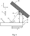
- Fig. 3 illustrates several distances that may be used by embodiments to determine the shortest longitudinal distance C form the exemplary left corner 56 of the vehicle 50 to the object 60 along the reversing direction y. It should be understood, the reversing direction could also be curved for which the shortest longitudinal distance C can still be calculated. However, to keep the calculation simple, it is assumed that the vehicle 50 reverses along a straight line (y-direction).
- the evaluation unit 110 receives from the radar unit 51 the closest distance R and the approaching angle ⁇ to the object 60.
- the determination may be based on multiple distances or a point cloud or even an image of the object 60 or any other information from where the closest distance R and the approaching angle ⁇ can be derived.
- the closest distance R is measured to the reflection point 65, which in this embodiment is not strictly behind the vehicle 50.
- a distance between the corner 56 and the radar unit 51 may be known and will be denoted by "a”.
- the evaluation unit 110 may further be configured to determine a reflection distance F.
- the evaluation unit 110 may be able to compensate any offset in the position of the radar unit 51 from a default or reference position (e.g. from a middle line of the vehicle 50).
- the corresponding information about the mounting position may be stored in the radar unit 51 or in the evaluation unit 110 or may be obtained from any storage device in the vehicle 50.
- the mounting position of the radar unit 51 can be arbitrary, i.e. the offset may relate to any spatial direction. According to embodiments, this information is known (e.g. there is a predetermined mounting position) and will be taken into account when determining the shortest longitudinal distances C. Hence, the offset can be compensated.
- the vehicle 50 may also include a driving unit that implements a highly automated driving (HAD). Therefore, a driver may or may not be present in the vehicle during driving and the driving unit may control the reversing operation without any input from the driver (who may act only as a supervisor).
- the reversing assistance device 100 helps not only a driver of the vehicle 50, but may also assist a driving unit, based on the shortest longitudinal distance information C information, to more accurately and reliably assess of the actual situation.
- Fig. 5 depicts a schematic diagram of different units of a vehicle 50 connected to each other via a communication link such as a controller area network, CAN bus 40, or ethernet or another data communication infrastructure.
- the vehicle 50 may comprise various control units such as a vehicle control unit 140 or a central control unit, a light control unit 130 to control the light indicators, a brake control unit 120, and a control unit integrated in the radar unit 51.
- the evaluation unit 110 can be in communication with all these control units via the exemplary CAN bus 40 and/or via wireless or via any radio communication to exchange data.
- the evaluation unit 110 may be integrated in one these control units, i.e. in the radar unit 51 or in the braking unit 120, or in the light control unit 130 or in the central unit 140.
- integration may mean that no additional component has to be added to the vehicle.
- both components cannot be separated from each other. All functions of the evaluation unit 110 can be implemented into the given control unit by installing respective software.
- embodiments relate also to an electronic control unit, ECU, including the reversing assistance device 100.
- the electronic control unit ECU is then configured to control a dedicated function (e.g. braking, lights) of the vehicle 50 and, in addition, the reversing assistance.
- a dedicated function e.g. braking, lights
- the reversing assistance device 100 is integrated into the brake control unit 120, it will control the vehicle braking as well as provides the reversing function.
- the evaluation unit 110 may further be configured to be placed in an idle state and an activated state.
- the evaluation unit 110 may provide the reversing support function only in the activated state.
- the activated state may be triggered by engaging a reverse gear by the driver and/or by a driving unit.
- the evaluation unit 110 may be triggered to be in the idle state when no reverse gear is engaged (by engaging a forward gear and/or parking gear) by the driver and/or driving unit.
- the evaluation unit 110 may further be configured to determine a speed V of the vehicle 50 and an acceleration of the vehicle 50.
- the evaluation unit 110 may be further configured to be in communication with internal sensors of the vehicle to obtain the speed V of the vehicle and the acceleration of the vehicle 50. Therefore, the actual reversing speed may be taken into account, for example, for a warning of an imminent collision.
- the evaluation unit 110 is configured to issue a signal to the driver or the driving unit, in case the determined shortest longitudinal distance C is shorter than a predefined threshold (e.g. 2 meters, 1 meter or less).
- the predefined threshold may be calculated by the evaluation unit 110 based on a speed V of the vehicle 50 and/or distance information obtained from the radar unit 51.
- the predefined threshold may be obtained from a control unit of the vehicle 50.
- the issued signal by the evaluation unit 110 may trigger at least one of the following: an acoustic signal, a blinking marker, a visual indicator in a cabin or visible through a window or mirror, an (electric) transmission of a warning to other systems (any vehicle ECU).
- the issued signal may have different intensity (e.g. loudness of the acoustic signal or the frequency of the blinking end-outline marker etc.) in relation with the value of the shortest longitudinal distance C.
- Fig. 6 depicts a flow diagram of a method 200, for assisting a vehicle 50 reversing.
- the vehicle 50 comprising the at least one radar unit 51 mounted on the rear 52 of the vehicle 50 and configured to provide distance information R, ⁇ when approaching an object 60 fully or partially behind the vehicle 50 under an approaching angle ⁇ .
- the method comprises the steps of:
- the method 200 may further comprise determining at least one of the following: a speed of the vehicle 50, an acceleration of the vehicle 50, the approaching angle ⁇ , a reflection distance F, a lateral distance b.
- the method 200 may also be a computer-implemented method.
- a person of skill in the art would readily recognize that steps of various above-described methods may be performed by programmed computers.
- Embodiments are also intended to cover program storage devices, e.g., digital data storage media, which are machine or computer-readable and encode machine-executable or computer-executable programs of instructions, wherein the instructions perform some or all of the acts of the above-described methods when executed on the computer or processor.
Landscapes
- Engineering & Computer Science (AREA)
- Radar, Positioning & Navigation (AREA)
- Remote Sensing (AREA)
- Physics & Mathematics (AREA)
- Computer Networks & Wireless Communication (AREA)
- General Physics & Mathematics (AREA)
- Electromagnetism (AREA)
- Mechanical Engineering (AREA)
- Transportation (AREA)
- Human Computer Interaction (AREA)
- Traffic Control Systems (AREA)
Claims (11)
- Dispositif d'aide à la marche arrière (100) pour un véhicule (50), le véhicule (50) comprenant une unité radar (51) montée à l'arrière (52) du véhicule (50) et configurée pour fournir des informations de distance (R, α) jusqu'à un objet (60) qui se trouve entièrement ou partiellement derrière le véhicule (50) lors de l'approche de l'objet (60) sous un angle d'approche α, caractérisé par :
une unité d'évaluation (110) configurée pour fournir une fonction de prise en charge de la marche arrière par :- l'obtention, depuis l'unité radar (51), des informations de distance (R, α) jusqu'à l'objet (60), dans lequel l'unité radar est configurée pour mesurer une distance minimale R la plus proche et un angle d'approche α de l'unité radar à un point de réflexion (65) d'un premier signal de retour ;- la détermination, sur la base des informations de distance (R, α), d'une distance longitudinale la plus courte C entre un coin (56) de l'arrière (52) du véhicule (50) et l'objet (60) le long d'une direction de marche arrière y du véhicule (50) ; etl'unité d'évaluation (110) est en outre configurée pour déterminer :- une distance longitudinale F entre l'arrière (52) du véhicule (50) et le point de réflexion (65) sur l'objet (60) mesurée selon la direction de marche arrière y, à l'aide de : F = R × sin α, dans laquelle R est la distance minimale R la plus proche et α est l'angle d'approche ;- la distance latérale b entre l'unité radar (51) et le point de réflexion (65) mesurée le long d'une direction latérale x à l'aide de : b = R × cos α, dans laquelle R est la distance minimale la plus proche et α est l'angle d'approche ;- la distance longitudinale la plus courte C, à l'aide de : C = F + (b-a) × b/F,dans laquelle « a » est une distance de l'unité radar (51) à un coin arrière (56) du véhicule (50),dans lequel la distance minimale R la plus proche de l'unité radar (51) à l'objet (60) représente le trajet de propagation du premier signal de retour, et la ligne de la distance minimale R la plus proche présente un angle rectangulaire avec un plan de surface de l'objet (60). - Dispositif selon la revendication 1, caractérisé en ce que
l'unité d'évaluation (110) est en outre configurée pour transmettre à d'autres systèmes au moins l'un des éléments suivants :- l'angle d'approche α ;- la distance minimale R la plus proche entre l'unité radar (51) et un point de réflexion (65) sur l'objet (60) ;- la distance longitudinale F entre l'arrière (52) du véhicule (50) et le point de réflexion (65) sur l'objet (60) mesurée selon la direction de marche arrière y, à l'aide de : F = R × sin α, dans laquelle R est la distance minimale R la plus proche et α est l'angle d'approche ;- la distance latérale b entre l'unité radar (51) et le point de réflexion (65) mesurée le long d'une direction latérale x à l'aide de : b = R × cos α, dans laquelle R est la distance minimale la plus proche et α est l'angle d'approche ;- la distance longitudinale la plus courte C, à l'aide de : C = F + (b-a) × b/F,dans laquelle « a » est une distance de l'unité radar (51) à un coin arrière (56) du véhicule (50),- une compensation pour un décalage d'une position de l'unité radar (51) par rapport à une position de référence. - Dispositif (100) selon la revendication 1 ou la revendication 2, dans lequel le véhicule (50) est conduit par un conducteur ou par une unité motrice,
caractérisé en ce que
l'unité d'évaluation (110) est en outre configurée pour délivrer un signal au conducteur ou à l'unité motrice, dans le cas où la distance longitudinale la plus courte C déterminée est inférieure à un seuil. - Dispositif (100) selon l'une quelconque des revendications précédentes,
caractérisé en ce que
l'unité d'évaluation (110) est configurée pour délivrer un signal d'alerte déclenchant au moins l'un des éléments suivants : un signal acoustique, un indicateur visuel dans une cabine ou au niveau du véhicule visible par le conducteur à travers la vitre latérale ou les rétroviseurs latéraux, une transmission d'un avertissement à d'autres systèmes. - Dispositif (100) selon l'une quelconque des revendications précédentes, dans lequel le véhicule (50) comprend en outre au moins un autre capteur (54) monté sur un côté du véhicule et configuré pour détecter l'objet (60) au niveau du côté du véhicule (50), caractérisé en ce que
l'unité d'évaluation (110) est en outre configurée pour recevoir un signal de détection de l'autre capteur (54) comme confirmation d'une présence de l'objet (60). - Unité de commande électronique, ECU,
caractérisée par
un dispositif (100) selon l'une quelconque des revendications précédentes. - ECU selon la revendication 6 qui est l'une parmi :- une unité de commande de frein (120),- une unité de commande d'éclairage (130),- une unité de commande électronique de véhicule (140),- une unité de commande de radar,- une unité télématique.
- Véhicule (50) incluant une unité radar (51),
caractérisé par
un dispositif (100) selon l'une des revendications 1 à 5 pour fournir une fonction de prise en charge de marche arrière ou une ECU selon la revendication 6 ou la revendication 7. - Véhicule (50) selon la revendication 8, dans lequel le véhicule inclut un tracteur et une remorque,
caractérisé en ce que
l'unité radar (51) est montée à l'arrière (52) de la remorque (53). - Procédé (200) d'aide d'un véhicule (50) pendant une marche arrière, le véhicule (50) comprenant une unité radar (51) montée à l'arrière (52) du véhicule (50) et configurée pour mesurer une distance minimale R la plus proche et un angle d'approche α entre l'unité radar et un point de réflexion (65) d'un premier signal de retour, afin de fournir des informations de distance (R, α) à l'approche d'un objet (60) qui se trouve entièrement ou partiellement derrière le véhicule (50) sous l'angle d'approche α, caractérisé par :- l'obtention (S210) d'informations de distance (R, α) jusqu'à l'objet (60) à partir de l'unité radar (51) ;- la détermination (S220), sur la base des informations de distance (R, α), de la distance longitudinale la plus courte C entre un coin (56) de l'arrière (52) du véhicule (50) et l'objet (60) le long de la direction de marche arrière y du véhicule (50) à l'approche de l'objet (60) ; et- la détermination d'une distance minimale R la plus proche entre l'unité radar (51) et un point de réflexion (65) sur l'objet (60),où l'étape de détermination (S220) de la distance longitudinale la plus courte C inclut la détermination de :- une distance longitudinale F entre l'arrière (52) du véhicule (50) et le point de réflexion (65) sur l'objet (60) mesurée selon la direction de marche arrière y, à l'aide de : F = R × sin α, dans laquelle R est la distance minimale R la plus proche et α est l'angle d'approche ;- la distance latérale b entre l'unité radar (51) et le point de réflexion (65) mesurée le long d'une direction latérale x à l'aide de : b = R × cos α, dans laquelle R est la distance minimale la plus proche et α est l'angle d'approche ;la distance longitudinale la plus courte C, à l'aide de : C = F + (b-a) × b/F, dans laquelle« a » est une distance entre l'unité radar (51) et un coin arrière (56) du véhicule (50), dans lequel la distance minimale R la plus proche de l'unité radar (51) à l'objet (60) représente le trajet de propagation du premier signal de retour, et la ligne de la distance minimale R la plus proche présente un angle rectangulaire avec un plan de surface de l'objet (60).
- Dispositif de stockage lisible par ordinateur (300) sur lequel est stocké un logiciel conçu pour mettre en œuvre le procédé d'aide à un véhicule (50) pendant une marche arrière selon la revendication 10 lorsque le logiciel est exécuté sur une unité de traitement de données, dans lequel le véhicule (50) comprendune unité radar (51) montée à l'arrière (52) du véhicule (50)et configurée pour mesurer une distance minimale R la plus proche et un angle d'approche a de l'unité radar à un point de réflexion (65) d'un premier signal de retour, à l'approche d'un objet (60), dans lequel la distance minimale R la plus proche de l'unité radar (51) à l'objet (60) représente le trajet de propagation du premier signal de retour, et la ligne de la distance minimale R la plus proche présente un angle rectangulaire avec un plan de surface de l'objet (60).
Priority Applications (4)
| Application Number | Priority Date | Filing Date | Title |
|---|---|---|---|
| PL21201301.5T PL4163672T3 (pl) | 2021-10-06 | 2021-10-06 | Urządzenie wspomagające cofanie i sposób wspomagania pojazdu podczas manewru cofania |
| EP21201301.5A EP4163672B1 (fr) | 2021-10-06 | 2021-10-06 | Dispositif d'aide à la marche arrière et procédé pour assister un véhicule pendant une opération en marche arrière |
| PCT/EP2022/076887 WO2023057265A1 (fr) | 2021-10-06 | 2022-09-28 | Dispositif d'aide à la marche arrière et procédé d'aide d'un véhicule lors d'une opération de marche arrière |
| US18/697,635 US20240411015A1 (en) | 2021-10-06 | 2022-09-28 | Reversing Assistance Device and Method for Assisting a Vehicle During Reversing Operation |
Applications Claiming Priority (1)
| Application Number | Priority Date | Filing Date | Title |
|---|---|---|---|
| EP21201301.5A EP4163672B1 (fr) | 2021-10-06 | 2021-10-06 | Dispositif d'aide à la marche arrière et procédé pour assister un véhicule pendant une opération en marche arrière |
Publications (2)
| Publication Number | Publication Date |
|---|---|
| EP4163672A1 EP4163672A1 (fr) | 2023-04-12 |
| EP4163672B1 true EP4163672B1 (fr) | 2025-06-25 |
Family
ID=78085568
Family Applications (1)
| Application Number | Title | Priority Date | Filing Date |
|---|---|---|---|
| EP21201301.5A Active EP4163672B1 (fr) | 2021-10-06 | 2021-10-06 | Dispositif d'aide à la marche arrière et procédé pour assister un véhicule pendant une opération en marche arrière |
Country Status (4)
| Country | Link |
|---|---|
| US (1) | US20240411015A1 (fr) |
| EP (1) | EP4163672B1 (fr) |
| PL (1) | PL4163672T3 (fr) |
| WO (1) | WO2023057265A1 (fr) |
Family Cites Families (4)
| Publication number | Priority date | Publication date | Assignee | Title |
|---|---|---|---|---|
| US6268803B1 (en) * | 1998-08-06 | 2001-07-31 | Altra Technologies Incorporated | System and method of avoiding collisions |
| DE102004059596B4 (de) * | 2004-12-09 | 2007-11-08 | Daimlerchrysler Ag | Verfahren zum Ermitteln eines Knickwinkels eines Fahrzeuggespanns sowie entsprechende Vorrichtung |
| DE102009007990A1 (de) * | 2009-02-07 | 2010-08-12 | Hella Kgaa Hueck & Co. | Verfahren zur Bestimmung von Anhängerdaten |
| US10871780B2 (en) * | 2018-01-30 | 2020-12-22 | Uatc, Llc | Intermediate mounting component and sensor system for a Mansfield bar of a cargo trailer |
-
2021
- 2021-10-06 PL PL21201301.5T patent/PL4163672T3/pl unknown
- 2021-10-06 EP EP21201301.5A patent/EP4163672B1/fr active Active
-
2022
- 2022-09-28 WO PCT/EP2022/076887 patent/WO2023057265A1/fr not_active Ceased
- 2022-09-28 US US18/697,635 patent/US20240411015A1/en active Pending
Also Published As
| Publication number | Publication date |
|---|---|
| EP4163672A1 (fr) | 2023-04-12 |
| US20240411015A1 (en) | 2024-12-12 |
| WO2023057265A1 (fr) | 2023-04-13 |
| PL4163672T3 (pl) | 2025-09-08 |
Similar Documents
| Publication | Publication Date | Title |
|---|---|---|
| US10011278B2 (en) | Collision avoidance system | |
| US20230202460A1 (en) | Vehicular trailer sway management system | |
| EP2313294B1 (fr) | Capteurs de longueur de véhicule | |
| EP3674155B1 (fr) | Appareil et procédé d'évitement de collisions | |
| US8831867B2 (en) | Device and method for driver assistance | |
| US20040051659A1 (en) | Vehicular situational awareness system | |
| CN110214346A (zh) | 用于检测车辆的挂车周围的物体的传感器布置结构和方法 | |
| US20070112516A1 (en) | Apparatus for reducing impact of vehicle crash | |
| CN103770730A (zh) | 识别路肩空间的方法和系统 | |
| US20190275993A1 (en) | Vehicle control apparatus and vehicle control method | |
| EP3441841A1 (fr) | Système de remorquage virtuel | |
| EP3957533A2 (fr) | Système de détection de véhicule | |
| JP2009075638A (ja) | 車種判別装置 | |
| US20210327274A1 (en) | Driving assistance device | |
| EP1528526B1 (fr) | Système de détection d'unités mobiles | |
| US20250083677A1 (en) | An Overtaking Assistance Device and Method for Assisting a Commercial Vehicle During Overtaking Another Vehicle | |
| JP4878870B2 (ja) | 道路形状推定装置、障害物検出装置および道路形状推定方法 | |
| US20240411015A1 (en) | Reversing Assistance Device and Method for Assisting a Vehicle During Reversing Operation | |
| CN210617998U (zh) | 一种用于货运和客运车辆的盲区检测设备 | |
| US12614463B2 (en) | Host vehicle blind spot monitoring system and host vehicle blind spot monitoring method | |
| US12405370B2 (en) | Method for radar-based monitoring of a rearward area | |
| JP2013045142A (ja) | 接近警報装置、接近警報方法、プログラム及び媒体 | |
| JP2002131425A (ja) | レーダ装置、車載用レーダ装置並びに衝突防止システム | |
| KR101127702B1 (ko) | 자동차의 통합 측/후방 안전시스템 | |
| JP7377054B2 (ja) | 制御装置 |
Legal Events
| Date | Code | Title | Description |
|---|---|---|---|
| PUAI | Public reference made under article 153(3) epc to a published international application that has entered the european phase |
Free format text: ORIGINAL CODE: 0009012 |
|
| STAA | Information on the status of an ep patent application or granted ep patent |
Free format text: STATUS: THE APPLICATION HAS BEEN PUBLISHED |
|
| AK | Designated contracting states |
Kind code of ref document: A1 Designated state(s): AL AT BE BG CH CY CZ DE DK EE ES FI FR GB GR HR HU IE IS IT LI LT LU LV MC MK MT NL NO PL PT RO RS SE SI SK SM TR |
|
| STAA | Information on the status of an ep patent application or granted ep patent |
Free format text: STATUS: REQUEST FOR EXAMINATION WAS MADE |
|
| 17P | Request for examination filed |
Effective date: 20231012 |
|
| RBV | Designated contracting states (corrected) |
Designated state(s): AL AT BE BG CH CY CZ DE DK EE ES FI FR GB GR HR HU IE IS IT LI LT LU LV MC MK MT NL NO PL PT RO RS SE SI SK SM TR |
|
| STAA | Information on the status of an ep patent application or granted ep patent |
Free format text: STATUS: EXAMINATION IS IN PROGRESS |
|
| 17Q | First examination report despatched |
Effective date: 20240103 |
|
| GRAP | Despatch of communication of intention to grant a patent |
Free format text: ORIGINAL CODE: EPIDOSNIGR1 |
|
| STAA | Information on the status of an ep patent application or granted ep patent |
Free format text: STATUS: GRANT OF PATENT IS INTENDED |
|
| INTG | Intention to grant announced |
Effective date: 20250225 |
|
| P01 | Opt-out of the competence of the unified patent court (upc) registered |
Free format text: CASE NUMBER: APP_14246/2025 Effective date: 20250324 |
|
| GRAS | Grant fee paid |
Free format text: ORIGINAL CODE: EPIDOSNIGR3 |
|
| GRAA | (expected) grant |
Free format text: ORIGINAL CODE: 0009210 |
|
| STAA | Information on the status of an ep patent application or granted ep patent |
Free format text: STATUS: THE PATENT HAS BEEN GRANTED |
|
| AK | Designated contracting states |
Kind code of ref document: B1 Designated state(s): AL AT BE BG CH CY CZ DE DK EE ES FI FR GB GR HR HU IE IS IT LI LT LU LV MC MK MT NL NO PL PT RO RS SE SI SK SM TR |
|
| REG | Reference to a national code |
Ref country code: GB Ref legal event code: FG4D |
|
| REG | Reference to a national code |
Ref country code: CH Ref legal event code: EP |
|
| REG | Reference to a national code |
Ref country code: CH Ref legal event code: EP |
|
| REG | Reference to a national code |
Ref country code: IE Ref legal event code: FG4D |
|
| REG | Reference to a national code |
Ref country code: DE Ref legal event code: R096 Ref document number: 602021032742 Country of ref document: DE |
|
| REG | Reference to a national code |
Ref country code: SE Ref legal event code: TRGR |
|
| PG25 | Lapsed in a contracting state [announced via postgrant information from national office to epo] |
Ref country code: FI Free format text: LAPSE BECAUSE OF FAILURE TO SUBMIT A TRANSLATION OF THE DESCRIPTION OR TO PAY THE FEE WITHIN THE PRESCRIBED TIME-LIMIT Effective date: 20250625 |
|
| REG | Reference to a national code |
Ref country code: LT Ref legal event code: MG9D |
|
| PG25 | Lapsed in a contracting state [announced via postgrant information from national office to epo] |
Ref country code: NO Free format text: LAPSE BECAUSE OF FAILURE TO SUBMIT A TRANSLATION OF THE DESCRIPTION OR TO PAY THE FEE WITHIN THE PRESCRIBED TIME-LIMIT Effective date: 20250925 Ref country code: GR Free format text: LAPSE BECAUSE OF FAILURE TO SUBMIT A TRANSLATION OF THE DESCRIPTION OR TO PAY THE FEE WITHIN THE PRESCRIBED TIME-LIMIT Effective date: 20250926 |
|
| PGFP | Annual fee paid to national office [announced via postgrant information from national office to epo] |
Ref country code: PL Payment date: 20250911 Year of fee payment: 5 |
|
| PG25 | Lapsed in a contracting state [announced via postgrant information from national office to epo] |
Ref country code: BG Free format text: LAPSE BECAUSE OF FAILURE TO SUBMIT A TRANSLATION OF THE DESCRIPTION OR TO PAY THE FEE WITHIN THE PRESCRIBED TIME-LIMIT Effective date: 20250625 |
|
| PG25 | Lapsed in a contracting state [announced via postgrant information from national office to epo] |
Ref country code: HR Free format text: LAPSE BECAUSE OF FAILURE TO SUBMIT A TRANSLATION OF THE DESCRIPTION OR TO PAY THE FEE WITHIN THE PRESCRIBED TIME-LIMIT Effective date: 20250625 |
|
| PG25 | Lapsed in a contracting state [announced via postgrant information from national office to epo] |
Ref country code: RS Free format text: LAPSE BECAUSE OF FAILURE TO SUBMIT A TRANSLATION OF THE DESCRIPTION OR TO PAY THE FEE WITHIN THE PRESCRIBED TIME-LIMIT Effective date: 20250925 |
|
| PG25 | Lapsed in a contracting state [announced via postgrant information from national office to epo] |
Ref country code: LV Free format text: LAPSE BECAUSE OF FAILURE TO SUBMIT A TRANSLATION OF THE DESCRIPTION OR TO PAY THE FEE WITHIN THE PRESCRIBED TIME-LIMIT Effective date: 20250625 |
|
| REG | Reference to a national code |
Ref country code: NL Ref legal event code: MP Effective date: 20250625 |
|
| PG25 | Lapsed in a contracting state [announced via postgrant information from national office to epo] |
Ref country code: NL Free format text: LAPSE BECAUSE OF FAILURE TO SUBMIT A TRANSLATION OF THE DESCRIPTION OR TO PAY THE FEE WITHIN THE PRESCRIBED TIME-LIMIT Effective date: 20250625 |
|
| PG25 | Lapsed in a contracting state [announced via postgrant information from national office to epo] |
Ref country code: PT Free format text: LAPSE BECAUSE OF FAILURE TO SUBMIT A TRANSLATION OF THE DESCRIPTION OR TO PAY THE FEE WITHIN THE PRESCRIBED TIME-LIMIT Effective date: 20251027 |
|
| REG | Reference to a national code |
Ref country code: AT Ref legal event code: MK05 Ref document number: 1807014 Country of ref document: AT Kind code of ref document: T Effective date: 20250625 |
|
| PG25 | Lapsed in a contracting state [announced via postgrant information from national office to epo] |
Ref country code: IS Free format text: LAPSE BECAUSE OF FAILURE TO SUBMIT A TRANSLATION OF THE DESCRIPTION OR TO PAY THE FEE WITHIN THE PRESCRIBED TIME-LIMIT Effective date: 20251025 |
|
| PGFP | Annual fee paid to national office [announced via postgrant information from national office to epo] |
Ref country code: DE Payment date: 20251028 Year of fee payment: 5 |
|
| PGFP | Annual fee paid to national office [announced via postgrant information from national office to epo] |
Ref country code: GB Payment date: 20251021 Year of fee payment: 5 |
|
| PG25 | Lapsed in a contracting state [announced via postgrant information from national office to epo] |
Ref country code: AT Free format text: LAPSE BECAUSE OF FAILURE TO SUBMIT A TRANSLATION OF THE DESCRIPTION OR TO PAY THE FEE WITHIN THE PRESCRIBED TIME-LIMIT Effective date: 20250625 Ref country code: SM Free format text: LAPSE BECAUSE OF FAILURE TO SUBMIT A TRANSLATION OF THE DESCRIPTION OR TO PAY THE FEE WITHIN THE PRESCRIBED TIME-LIMIT Effective date: 20250625 |
|
| PGFP | Annual fee paid to national office [announced via postgrant information from national office to epo] |
Ref country code: SE Payment date: 20251024 Year of fee payment: 5 |
|
| PG25 | Lapsed in a contracting state [announced via postgrant information from national office to epo] |
Ref country code: CZ Free format text: LAPSE BECAUSE OF FAILURE TO SUBMIT A TRANSLATION OF THE DESCRIPTION OR TO PAY THE FEE WITHIN THE PRESCRIBED TIME-LIMIT Effective date: 20250625 |
|
| PG25 | Lapsed in a contracting state [announced via postgrant information from national office to epo] |
Ref country code: EE Free format text: LAPSE BECAUSE OF FAILURE TO SUBMIT A TRANSLATION OF THE DESCRIPTION OR TO PAY THE FEE WITHIN THE PRESCRIBED TIME-LIMIT Effective date: 20250625 |
|
| PG25 | Lapsed in a contracting state [announced via postgrant information from national office to epo] |
Ref country code: SK Free format text: LAPSE BECAUSE OF FAILURE TO SUBMIT A TRANSLATION OF THE DESCRIPTION OR TO PAY THE FEE WITHIN THE PRESCRIBED TIME-LIMIT Effective date: 20250625 |
|
| PG25 | Lapsed in a contracting state [announced via postgrant information from national office to epo] |
Ref country code: ES Free format text: LAPSE BECAUSE OF FAILURE TO SUBMIT A TRANSLATION OF THE DESCRIPTION OR TO PAY THE FEE WITHIN THE PRESCRIBED TIME-LIMIT Effective date: 20250625 |
|
| PG25 | Lapsed in a contracting state [announced via postgrant information from national office to epo] |
Ref country code: RO Free format text: LAPSE BECAUSE OF FAILURE TO SUBMIT A TRANSLATION OF THE DESCRIPTION OR TO PAY THE FEE WITHIN THE PRESCRIBED TIME-LIMIT Effective date: 20250625 |
|
| PG25 | Lapsed in a contracting state [announced via postgrant information from national office to epo] |
Ref country code: DK Free format text: LAPSE BECAUSE OF FAILURE TO SUBMIT A TRANSLATION OF THE DESCRIPTION OR TO PAY THE FEE WITHIN THE PRESCRIBED TIME-LIMIT Effective date: 20250625 |
|
| PG25 | Lapsed in a contracting state [announced via postgrant information from national office to epo] |
Ref country code: IT Free format text: LAPSE BECAUSE OF FAILURE TO SUBMIT A TRANSLATION OF THE DESCRIPTION OR TO PAY THE FEE WITHIN THE PRESCRIBED TIME-LIMIT Effective date: 20250625 |
|
| PLBE | No opposition filed within time limit |
Free format text: ORIGINAL CODE: 0009261 |
|
| STAA | Information on the status of an ep patent application or granted ep patent |
Free format text: STATUS: NO OPPOSITION FILED WITHIN TIME LIMIT |
|
| REG | Reference to a national code |
Ref country code: CH Ref legal event code: L10 Free format text: ST27 STATUS EVENT CODE: U-0-0-L10-L00 (AS PROVIDED BY THE NATIONAL OFFICE) Effective date: 20260507 |