EP4163675B1 - Beleuchtung einer umgebung zur lokalisierung - Google Patents
Beleuchtung einer umgebung zur lokalisierung Download PDFInfo
- Publication number
- EP4163675B1 EP4163675B1 EP22210357.4A EP22210357A EP4163675B1 EP 4163675 B1 EP4163675 B1 EP 4163675B1 EP 22210357 A EP22210357 A EP 22210357A EP 4163675 B1 EP4163675 B1 EP 4163675B1
- Authority
- EP
- European Patent Office
- Prior art keywords
- illumination
- user device
- determiner
- elements
- key element
- Prior art date
- Legal status (The legal status is an assumption and is not a legal conclusion. Google has not performed a legal analysis and makes no representation as to the accuracy of the status listed.)
- Active
Links
Images

Classifications
-
- G—PHYSICS
- G06—COMPUTING OR CALCULATING; COUNTING
- G06F—ELECTRIC DIGITAL DATA PROCESSING
- G06F3/00—Input arrangements for transferring data to be processed into a form capable of being handled by the computer; Output arrangements for transferring data from processing unit to output unit, e.g. interface arrangements
- G06F3/01—Input arrangements or combined input and output arrangements for interaction between user and computer
- G06F3/03—Arrangements for converting the position or the displacement of a member into a coded form
- G06F3/0304—Detection arrangements using opto-electronic means
-
- G—PHYSICS
- G06—COMPUTING OR CALCULATING; COUNTING
- G06F—ELECTRIC DIGITAL DATA PROCESSING
- G06F3/00—Input arrangements for transferring data to be processed into a form capable of being handled by the computer; Output arrangements for transferring data from processing unit to output unit, e.g. interface arrangements
- G06F3/002—Specific input/output arrangements not covered by G06F3/01 - G06F3/16
- G06F3/005—Input arrangements through a video camera
-
- G—PHYSICS
- G06—COMPUTING OR CALCULATING; COUNTING
- G06F—ELECTRIC DIGITAL DATA PROCESSING
- G06F3/00—Input arrangements for transferring data to be processed into a form capable of being handled by the computer; Output arrangements for transferring data from processing unit to output unit, e.g. interface arrangements
- G06F3/01—Input arrangements or combined input and output arrangements for interaction between user and computer
- G06F3/011—Arrangements for interaction with the human body, e.g. for user immersion in virtual reality
-
- G—PHYSICS
- G06—COMPUTING OR CALCULATING; COUNTING
- G06V—IMAGE OR VIDEO RECOGNITION OR UNDERSTANDING
- G06V10/00—Arrangements for image or video recognition or understanding
- G06V10/10—Image acquisition
- G06V10/12—Details of acquisition arrangements; Constructional details thereof
- G06V10/14—Optical characteristics of the device performing the acquisition or on the illumination arrangements
- G06V10/141—Control of illumination
-
- G—PHYSICS
- G06—COMPUTING OR CALCULATING; COUNTING
- G06V—IMAGE OR VIDEO RECOGNITION OR UNDERSTANDING
- G06V20/00—Scenes; Scene-specific elements
- G06V20/10—Terrestrial scenes
-
- H—ELECTRICITY
- H04—ELECTRIC COMMUNICATION TECHNIQUE
- H04N—PICTORIAL COMMUNICATION, e.g. TELEVISION
- H04N13/00—Stereoscopic video systems; Multi-view video systems; Details thereof
- H04N13/20—Image signal generators
- H04N13/204—Image signal generators using stereoscopic image cameras
- H04N13/254—Image signal generators using stereoscopic image cameras in combination with electromagnetic radiation sources for illuminating objects
Definitions
- US2015/229915 A1 refers to a method for controlling the intensity of illumination of a scene or part of a scene, where the illumination intensity is controllably varied to obtain sufficient quality while saving power, so that control is directed to one or more regions of interest, corresponding to an entire scene or part of a scene.
- the step of adjusting illumination may comprise matching the illumination with an illumination applied for the stored data of the at least a subset of the at least one key element.
- the step of determining a need for light source adaptation may consider illumination from a light source of another user device.
- the step of determining a field of view may be based on a pose of the at least one camera of the user device.
- the method may further comprise the step of: predicting movement of at least one of the user device and a key element, in which case the step of adjusting illumination is based on the predicted movement.
- the step of predicting movement may comprise predicting movement of the user device to a location where light conditions are different from current light conditions; in which case the step of adjusting illumination comprises gradually adjusting intensity of the light source.
- the method may further comprise the step of: determining, for each key element, whether a level of illumination of the key element needs to be adjusted: in which case the step of adjusting illumination may comprise only adjusting the illumination for any key element for which illumination needs to be adjusted.
- the step of adjusting illumination may comprise directing the light source.
- the method may further comprise the steps of: inactivating illumination once the user device has been positioned; and entering a sleep state for a sleep period before the method is repeated.
- an illumination determiner for illuminating an environment for localisation of a user device comprising a light source and at least one camera as defined in appended claim 3.
- the illumination determiner among others comprises: a processor; and a memory storing instructions that, when executed by the processor, cause the illumination determiner to: determine a need for adjusting illumination; determine a field of view of the at least one camera of the user device; obtain environment data for elements within the field of view from previously stored environment data; select at least one key element of the elements; and adjust illumination of at least a subset of the at least one key element by adapting a light source.
- the instructions to select at least one key element comprise instructions that, when executed by the processor, cause the illumination determiner to rank the elements according to importance for SLAM and selecting a number of the highest ranked elements.
- the instructions to determine a need for light source adaptation may comprise instructions that, when executed by the processor, cause the illumination determiner to consider illumination from a light source of another user device.
- the instructions to determine a need for light source adaptation comprise instructions that, when executed by the processor, cause the illumination determiner to determine a need for light source adaptation based on receiving a signal, from another user device, indicating a required change of light situation in the field of view.
- the instructions to determine a field of view may comprise instructions that, when executed by the processor, cause the illumination determiner to determine a field of view based on a pose of the at least one camera of the user device.
- the illumination determiner may further comprise instructions that, when executed by the processor, cause the illumination determiner to: predict movement of at least one of the user device and a key element, in which case the instructions to adjust illumination comprise instructions that, when executed by the processor, cause the illumination determiner to adjust illumination based on the predicted movement.
- the instructions to predict movement may comprise instructions that, when executed by the processor, cause the illumination determiner to predict movement of the user device to a location where light conditions are different from current light conditions; in which case the instructions to adjust illumination comprise instructions that, when executed by the processor, cause the illumination determiner to gradually adjust intensity of the light source.
- the illumination determiner may further comprise instructions that, when executed by the processor, cause the illumination determiner to: determine, for each key element, whether a level of illumination of the key element needs to be adjusted; in which case the instructions to adjust illumination comprise instructions that, when executed by the processor, cause the illumination determiner to only adjust the illumination for any key element for which illumination needs to be adjusted.
- the instructions to adjust illumination may comprise instructions that, when executed by the processor, cause the illumination determiner to direct the light source.
- the illumination determiner may further comprise instructions that, when executed by the processor, cause the illumination determiner to: inactivate illumination once the user device has been positioned; and enter a sleep state for a sleep period before the method is repeated.
- a computer program for illuminating an environment for localisation of a user device comprising a light source and at least one camera as defined in appended claim 11.
- a computer program product comprising a computer program according to the third aspect and a computer readable means on which the computer program is stored.
- SLAM Simultaneous localisation and mapping'
- ⁇ field of view' is used herein, it is to be interpreted as the visible field of e.g. a camera or a user.
- the field of view can be defined e.g. by the aperture of a camera or the angles that are visible by an eye of a user.
- ⁇ user device' is used herein, it is to be interpreted as a device of a user.
- the user device is used for localisation of itself and optionally of mapping its environment, e.g. using SLAM.
- the user device is portable and can e.g. be a head mounted display, a smartphone, a tablet computer, etc.
- ⁇ environment data' is used herein, it is to be interpreted as data of a model describing elements of an environment in a two or three dimensional space.
- the environment data can be in the form of at least one pixel, a region or a complete image, or at least one voxel, or a region or a complete point cloud or polygon mesh.
- ⁇ light source' is used herein, it is to be interpreted as any device that is capable of emitting light.
- the light can be within a visible range or in an infrared range.
- Embodiments presented herein relate to illumination for localisation of a user device, where the localisation is based on at least one camera of the user device.
- the method is based on identification and selection of key elements in the environment.
- a light source is adjusted to achieve appropriate illumination of the key elements to enable localisation.
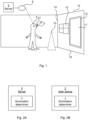
- Fig 1 is a schematic diagram illustrating an environment in which embodiments presented herein can be applied.
- the environment shown in Fig 1 is used for AR, where a user 5 wears a user device 2, such as a head mounted display (HMD), which allows the user 5 to see both real-world objects 11-16 and a virtual object 10.
- the user device 2 contains sensors (e.g. accelerometers, gyros, etc.) e.g. as part of an inertia measurement unit (IMU) which can form part of data used to determine the position and orientation of the user device 2 in a three dimensional space.
- sensors e.g. accelerometers, gyros, etc.
- IMU inertia measurement unit
- the user device 2 comprises one or more cameras 20 for capturing images of the environment around the user 5.
- Each camera 20 can be in the visible light range (also known as RGB, red green blue) and/or the infrared range. It is to be noted that the cameras do not need to be directed in a direction which is visible for the user, especially when used for localisation, as described in more detail below.
- the user device 2 further comprises one or more light sources 21.
- Each light source can be in the visible light range and/or the infrared range.
- one or more of the light sources 21 can be controlled to alter a direction of illumination.
- the light source can be controlled to change its intensity, using either an on/off control or a gradual (dimming or brightening) control.
- Each light source may comprise any one or more of an array of light emitting diodes (LEDs), an array of lasers, or a vertical cavity surface emitting laser (VCSEL) array.
- LEDs light emitting diodes
- VCSEL vertical cavity surface emitting laser
- the user device 2 is connected to a network 9.
- the network 9 can e.g. be a local area network (LAN) and/or a wide area network (WAN) such as the Internet.
- a server 3 is also connected to the network 9.
- Environment data (two-dimensional or three-dimensional) is obtained from storage of the user device 2 and/or the server 3. Key elements are identified in the images and compared with the environment data to allow the user device to be positioned within the environment, optionally also using data from the IMU.
- the key elements can be any subset (or all) of the visual elements 11-16. It is to be noted that the visual elements vary depending on where the user 5 is located. Mapping can also occur simultaneously, whereby the environment data is updated. A process of learning an area while keeping track of a current position and orientation of a user within the area is known as Simultaneous Localisation and Mapping, or SLAM.
- a virtual object 10 can be rendered by the user device 2 for AR purposes.
- the virtual object 10 does not exist in reality but is computer rendered.
- the virtual object has a position that corresponds to a real-world position, whereby the user device 2 should be positioned prior to the virtual object 10 being rendered.
- the user device 2 can e.g. be implemented using an HMD such as the Microsoft Hololens, or ODG R7/R8/R9.
- the HMD may also be an or Oculus Rift or HTC Vive for VR applications.
- the user device 2 is implemented using a smartphone and/or a tablet computer.
- the term 'computer' used herein is to be interpreted as any electronic device with digital processing capabilities, regardless of size.
- the term computer comprises devices such as servers, desktop computers, laptop computers, tablet computers, smart phones, mobile phones, smart watches, etc.
- the locating of the user device 2 based on key elements depends on there being an appropriate amount of light. According to embodiments presented herein, illumination is concentrated to key elements. This achieves a more efficient energy usage while ensuring the locating can be performed satisfactorily.
- Fig 1 the environment of Fig 1 is only one example of where the illumination for locating presented herein can be applied. Embodiments presented herein can equally well be applied in other environments such as for self-driving vehicles, industrial applications, indoor robotics, etc.
- the illumination determiner is shown as implemented in the server 3.
- the server is thus the host device for the illumination determiner.
- the illumination determiner is shown as implemented in the user device 2.
- the user device is thus the host device for the illumination determiner.
- light conditions can be inferred via the analysis of an image captured by the user device. This implies that the light conditions are extracted from an image of the environment taken from one of the cameras of the user device. If the light conditions are determined to be lower than a threshold, this can be a trigger that there is a need for adjustment of the illumination.
- the need for adjustment of illumination is also based on data relating to illumination from a light source of another user device.
- the need for adjustment of illumination is determined based on receiving a signal, from another user device, indicating a required change of light situation in the field of view (of the camera).
- the need for adjustment of illumination is determined by an element detection algorithm based on images captured by the user device. Such an algorithm may be unable to find sufficient elements to successfully perform the localisation, whereby additional illumination might be required.
- the illumination determiner determines a field of view of the at least one camera of the user device.
- key elements of an environment where a light source should project its light are selected.
- energy and heat spent on the illumination process is reduced, compared to illuminating the whole scene.
- the user experience is also less degraded than if one illuminates the complete scene.
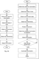
- An illumination need determiner 70 corresponds to step 40 of Figs 3A-B .
- a FOV (Field of View) determiner 72 corresponds to step 42 of Figs 3A-B .
- a data obtainer 74 corresponds to step 44 of Figs 3A-B .
- a key element selector 76 corresponds to step 46 of Figs 3A-B .
- a movement predictor 78 corresponds to step 48 of Fig 3B .
- An illumination sufficiency determiner 80 corresponds to step 50 of Fig 3B .
- An illumination adjuster 82 corresponds to step 52 of Figs 3A-B .
- a position status determiner 83 corresponds to step 53 of Fig 3B .
- An illumination inactivator 84 corresponds to step 54 of Fig 3B .
- a sleeper 86 corresponds to step 56 of Fig 3B .
Landscapes
- Engineering & Computer Science (AREA)
- Theoretical Computer Science (AREA)
- Physics & Mathematics (AREA)
- General Physics & Mathematics (AREA)
- General Engineering & Computer Science (AREA)
- Multimedia (AREA)
- Human Computer Interaction (AREA)
- Electromagnetism (AREA)
- Signal Processing (AREA)
- Circuit Arrangement For Electric Light Sources In General (AREA)
- Computer Networks & Wireless Communication (AREA)
- Radar, Positioning & Navigation (AREA)
- Remote Sensing (AREA)
- Studio Devices (AREA)
- User Interface Of Digital Computer (AREA)
Claims (12)
- Verfahren zur Beleuchtung einer Umgebung zum Lokalisieren einer Benutzervorrichtung (2) bei Anwendung einer Technik zur simultanen Positionsbestimmung und Kartierung, SLAM, wobei die Benutzervorrichtung (2) eine Lichtquelle und mindestens eine Kamera umfasst, wobei das Verfahren in einer Beleuchtungsbestimmungseinrichtung (1) durchgeführt wird und umfasst:Bestimmen (40) einer Notwendigkeit zur Anpassung von Beleuchtung, wobei der Schritt zum Bestimmen einer Notwendigkeit zur Anpassung von Beleuchtung auf dem Empfang eines Signals von einer anderen Benutzervorrichtung (2b) basiert, das eine erforderliche Änderung der Lichtsituation im Sichtfeld der mindestens einen Kamera anzeigt;Bestimmen (42) eines Sichtfeldes der mindestens einen Kamera der Benutzervorrichtung (2);Erhalten (44) von Umgebungsdaten für Elemente innerhalb des Sichtfeldes aus zuvor gespeicherten Umgebungsdaten, wobei die Umgebungsdaten Elemente enthalten, die mit Bildern verglichen werden können, die von der Benutzervorrichtung aufgenommen wurden, um dadurch eine Position der Benutzervorrichtung zu bestimmen, wobei jedes Element der Umgebungsdaten einen Satz von 2D- oder 3D-Koordinaten umfasst,Auswählen (46) mindestens eines Schlüsselelements der Elemente, wobei die Schlüsselelemente von größerer Wichtigkeit für die simultane Positionsbestimmung und Kartierung, SLAM, sind als Nicht-Schlüsselelemente, und wobei der Schritt des Auswählens (46) mindestens eines Schlüsselelements ein Reihen von Elementen gemäß ihrer Wichtigkeit für die SLAM und Auswählen einer Anzahl der am höchsten gereihten Elemente umfasst, undAnpassen (52) der Beleuchtung zumindest einer Teilmenge des mindestens einen ausgewählten Schlüsselelements durch Einrichten der Lichtquelle, um dadurch eine verbesserte Positionsbestimmung der Benutzervorrichtung (2) zu ermöglichen.
- Verfahren nach dem vorhergehenden Anspruch, wobei der Schritt des Anpassens (52) der Beleuchtung ein Vergleichen der Beleuchtung mit einer für die gespeicherten Daten der mindestens einen Teilmenge des mindestens einen Schlüsselelements angewendeten Beleuchtung umfasst.
- Beleuchtungsbestimmungseinrichtung (1), die eine Vorrichtung ist, die bei Anwenden einer Technik zur simultanen Positionsbestimmung und Kartierung, SLAM, bestimmt, ob Beleuchtung zur Positionsbestimmung einer Benutzervorrichtung (2) angepasst werden muss, wobei die Benutzervorrichtung (2) eine Lichtquelle und mindestens eine Kamera umfasst, wobei die Beleuchtungsbestimmungseinrichtung (1) konfiguriert ist zum:Bestimmen einer Notwendigkeit zur Anpassung von Beleuchtung basierend auf dem Empfang eines Signals von einer anderen Benutzervorrichtung (2b), das eine erforderliche Änderung der Lichtsituation im Sichtfeld der mindestens einen Kamera anzeigt;Bestimmen eines Sichtfeldes der mindestens einen Kamera der Benutzervorrichtung (2);Erhalten von Umgebungsdaten für Elemente innerhalb des Sichtfeldes aus zuvor gespeicherten Umgebungsdaten, wobei die Umgebungsdaten Elemente enthalten, die mit Bildern verglichen werden können, die von der Benutzervorrichtung aufgenommen wurden, um dadurch eine Position der Benutzervorrichtung zu bestimmen, wobei jedes Element der Umgebungsdaten einen Satz von 2D- oder 3D-Koordinaten umfasst,Auswählen mindestens eines Schlüsselelements der Elemente, wobei die Schlüsselelemente von größerer Wichtigkeit für die simultane Positionsbestimmung und Kartierung, SLAM, sind als Nicht-Schlüsselelemente, und wobei der Schritt des Auswählens (46) mindestens eines Schlüsselelements ein Reihen von Elementen gemäß ihrer Wichtigkeit für die SLAM und Auswählen einer Anzahl der am höchsten gereihten Elemente umfasst, undAnpassen der Beleuchtung zumindest einer Teilmenge des mindestens einen ausgewählten Schlüsselelements durch Einrichten der Lichtquelle, um dadurch eine verbesserte Positionsbestimmung der Benutzervorrichtung (2) zu ermöglichen.
- Beleuchtungsbestimmungseinrichtung (1) nach Anspruch 3, konfiguriert zum Veranlassen der Beleuchtungsbestimmungseinrichtung (1), die Beleuchtung mit einer für die gespeicherten Daten der mindestens einen Teilmenge des mindestens einen Schlüsselelements angewendeten Beleuchtung zu vergleichen.
- Beleuchtungsbestimmungseinrichtung (1) nach einem der Ansprüche 3 oder 4, konfiguriert zum Veranlassen der Beleuchtungsbestimmungseinrichtung (1), Beleuchtung von einer Lichtquelle einer anderen Benutzervorrichtung (2b) zu berücksichtigen.
- Beleuchtungsbestimmungseinrichtung (1) nach einem der Ansprüche 3 bis 5, konfiguriert zum Veranlassen der Beleuchtungsbestimmungseinrichtung (1), ein Sichtfeld basierend auf einer Stellung der mindestens einen Kamera der Benutzervorrichtung (2) zu bestimmen.
- Beleuchtungsbestimmungseinrichtung (1) nach einem der Ansprüche 3 bis 6, ferner konfiguriert zum Verwenden der Beleuchtungsbestimmungseinrichtung (1) zum:Vorhersagen von Bewegung mindestens eines von den Benutzervorrichtungen (2) und einem Schlüsselelement;und wobei die Anweisungen zum Anpassen der Beleuchtung Anweisungen (67) umfassen, die bei Ausführung durch den Prozessor die Beleuchtungsbestimmungseinrichtung (1) zum Anpassen der Beleuchtung basierend auf der vorhergesagten Bewegung veranlassen.
- Beleuchtungsbestimmungseinrichtung (1) nach Anspruch 7, konfiguriert zum Veranlassen der Beleuchtungsbestimmungseinrichtung (1), Bewegung der Benutzervorrichtung (2) in eine Position vorherzusagen, in der sich Lichtbedingungen von aktuellen Lichtbedingungen unterscheiden; und wobei die Anweisungen zum Anpassen der Beleuchtung Anweisungen (67) umfassen, die bei Ausführung durch den Prozessor die Beleuchtungsbestimmungseinrichtung (1) veranlassen, eine Intensität der Lichtquelle allmählich anzupassen.
- Beleuchtungsbestimmungseinrichtung (1) nach einem der Ansprüche 4 bis 10, ferner konfiguriert zum Veranlassen der Beleuchtungsbestimmungseinrichtung (1) zum:Bestimmen für jedes Schlüsselelement, ob ein Beleuchtungsniveau des Schlüsselelements angepasst werden muss;und wobei die Anweisung zum Anpassen der Beleuchtung Anweisungen (67) umfasst, die bei Ausführung durch den Prozessor die Beleuchtungsbestimmungseinrichtung (1) veranlassen, die Beleuchtung nur für jedes Schlüsselelement anzupassen, für das die Beleuchtung angepasst werden muss.
- Beleuchtungsbestimmungseinrichtung (1) nach einem der Ansprüche 4 bis 11, ferner konfiguriert zum Veranlassen der Beleuchtungsbestimmungseinrichtung (1) zum:Deaktivieren der Beleuchtung, sobald die Benutzervorrichtung (2) positioniert wurde; undEintreten in einen Schlafzustand für eine Schlafperiode, bevor das Verfahren nach Anspruch 1 wiederholt wird.
- Computerprogramm (67, 91) zum Beleuchten einer Umgebung zum Lokalisieren einer Benutzervorrichtung (2) bei Anwendung einer Technik zur simultanen Positionsbestimmung und Kartierung, SLAM, wobei die Benutzervorrichtung (2) eine Lichtquelle und mindestens eine Kamera umfasst, wobei das Computerprogramm Computerprogrammcode umfasst, der bei Ausführung auf einer Beleuchtungsbestimmungseinrichtung (1) die Beleuchtungsbestimmungseinrichtung (1) zum Ausführen des Verfahrens nach Anspruch 1 veranlasst.
- Computerprogrammprodukt (64, 90), umfassend ein Computerprogramm nach Anspruch 11 und ein computerlesbares Medium, auf welchem das Computerprogramm gespeichert ist.
Priority Applications (1)
| Application Number | Priority Date | Filing Date | Title |
|---|---|---|---|
| EP22210357.4A EP4163675B1 (de) | 2017-04-05 | 2017-04-05 | Beleuchtung einer umgebung zur lokalisierung |
Applications Claiming Priority (3)
| Application Number | Priority Date | Filing Date | Title |
|---|---|---|---|
| EP17717350.7A EP3607353B1 (de) | 2017-04-05 | 2017-04-05 | Beleuchtung einer umgebung zur lokalisierung |
| PCT/EP2017/058135 WO2018184675A1 (en) | 2017-04-05 | 2017-04-05 | Illuminating an environment for localisation |
| EP22210357.4A EP4163675B1 (de) | 2017-04-05 | 2017-04-05 | Beleuchtung einer umgebung zur lokalisierung |
Related Parent Applications (2)
| Application Number | Title | Priority Date | Filing Date |
|---|---|---|---|
| EP17717350.7A Division EP3607353B1 (de) | 2017-04-05 | 2017-04-05 | Beleuchtung einer umgebung zur lokalisierung |
| EP17717350.7A Division-Into EP3607353B1 (de) | 2017-04-05 | 2017-04-05 | Beleuchtung einer umgebung zur lokalisierung |
Publications (3)
| Publication Number | Publication Date |
|---|---|
| EP4163675A1 EP4163675A1 (de) | 2023-04-12 |
| EP4163675C0 EP4163675C0 (de) | 2024-07-03 |
| EP4163675B1 true EP4163675B1 (de) | 2024-07-03 |
Family
ID=58547487
Family Applications (2)
| Application Number | Title | Priority Date | Filing Date |
|---|---|---|---|
| EP17717350.7A Active EP3607353B1 (de) | 2017-04-05 | 2017-04-05 | Beleuchtung einer umgebung zur lokalisierung |
| EP22210357.4A Active EP4163675B1 (de) | 2017-04-05 | 2017-04-05 | Beleuchtung einer umgebung zur lokalisierung |
Family Applications Before (1)
| Application Number | Title | Priority Date | Filing Date |
|---|---|---|---|
| EP17717350.7A Active EP3607353B1 (de) | 2017-04-05 | 2017-04-05 | Beleuchtung einer umgebung zur lokalisierung |
Country Status (3)
| Country | Link |
|---|---|
| US (1) | US11163379B2 (de) |
| EP (2) | EP3607353B1 (de) |
| WO (1) | WO2018184675A1 (de) |
Families Citing this family (4)
| Publication number | Priority date | Publication date | Assignee | Title |
|---|---|---|---|---|
| EP3607353B1 (de) * | 2017-04-05 | 2023-03-01 | Telefonaktiebolaget LM Ericsson (PUBL) | Beleuchtung einer umgebung zur lokalisierung |
| US12514419B2 (en) * | 2021-12-27 | 2026-01-06 | Trifo, Inc. | Occupancy map segmentation for autonomous guided platform with deep learning |
| US20250308170A1 (en) * | 2024-03-28 | 2025-10-02 | Adeia Guides Inc. | Methods to improve passthrough experience in low light conditions |
| CN119417352B (zh) * | 2024-10-14 | 2025-08-15 | 山西尚旌珠宝首饰有限公司 | 一种数字化珠宝盘点控制系统 |
Family Cites Families (30)
| Publication number | Priority date | Publication date | Assignee | Title |
|---|---|---|---|---|
| US7626569B2 (en) * | 2004-10-25 | 2009-12-01 | Graphics Properties Holdings, Inc. | Movable audio/video communication interface system |
| EP1996959A4 (de) * | 2006-03-03 | 2012-02-29 | Medic Vision Brain Technologies Ltd | System und verfahren zur automatischen priorisierung und analyse medizinischer bilder |
| WO2011106520A1 (en) * | 2010-02-24 | 2011-09-01 | Ipplex Holdings Corporation | Augmented reality panorama supporting visually impaired individuals |
| US8620093B2 (en) * | 2010-03-15 | 2013-12-31 | The United States Of America As Represented By The Secretary Of The Army | Method and system for image registration and change detection |
| US20120306850A1 (en) * | 2011-06-02 | 2012-12-06 | Microsoft Corporation | Distributed asynchronous localization and mapping for augmented reality |
| US10209771B2 (en) * | 2016-09-30 | 2019-02-19 | Sony Interactive Entertainment Inc. | Predictive RF beamforming for head mounted display |
| US20140139632A1 (en) * | 2012-11-21 | 2014-05-22 | Lsi Corporation | Depth imaging method and apparatus with adaptive illumination of an object of interest |
| US9536345B2 (en) * | 2012-12-26 | 2017-01-03 | Intel Corporation | Apparatus for enhancement of 3-D images using depth mapping and light source synthesis |
| US9407837B2 (en) * | 2013-02-28 | 2016-08-02 | Google Inc. | Depth sensor using modulated light projector and image sensor with color and IR sensing |
| US10037689B2 (en) * | 2015-03-24 | 2018-07-31 | Donald Warren Taylor | Apparatus and system to manage monitored vehicular flow rate |
| EP2821750A1 (de) * | 2013-07-04 | 2015-01-07 | Hexagon Technology Center GmbH | Positionsbestimmungsverfahren für ein Vermessungsgerät und ebensolches Vermessungsgerät |
| US11265534B2 (en) * | 2014-02-08 | 2022-03-01 | Microsoft Technology Licensing, Llc | Environment-dependent active illumination for stereo matching |
| CN104299261B (zh) * | 2014-09-10 | 2017-01-25 | 深圳大学 | 人体三维成像方法及系统 |
| US20160178991A1 (en) * | 2014-12-22 | 2016-06-23 | Google Inc. | Smart illumination time of flight system and method |
| US20180361584A1 (en) * | 2015-01-06 | 2018-12-20 | Discovery Robotics | Robotic platform with long-term learning |
| US11400595B2 (en) * | 2015-01-06 | 2022-08-02 | Nexus Robotics Llc | Robotic platform with area cleaning mode |
| CN105120257B (zh) * | 2015-08-18 | 2017-12-15 | 宁波盈芯信息科技有限公司 | 一种基于结构光编码的垂直深度感知装置 |
| GB2541884A (en) * | 2015-08-28 | 2017-03-08 | Imp College Of Science Tech And Medicine | Mapping a space using a multi-directional camera |
| US10531074B2 (en) * | 2015-10-16 | 2020-01-07 | CapsoVision, Inc. | Endoscope employing structured light providing physiological feature size measurement |
| WO2017123761A1 (en) * | 2016-01-15 | 2017-07-20 | Irobot Corporation | Autonomous monitoring robot systems |
| US11087272B2 (en) * | 2016-03-29 | 2021-08-10 | Bossa Nova Robotics Ip, Inc. | System and method for locating, identifying and counting items |
| US10957059B1 (en) * | 2016-09-08 | 2021-03-23 | Facebook Technologies, Llc | Multi-pattern depth camera assembly |
| US20180085927A1 (en) * | 2016-09-28 | 2018-03-29 | International Business Machines Corporation | Optimizing a layout of objects in a space |
| US10158845B2 (en) * | 2017-01-18 | 2018-12-18 | Facebook Technologies, Llc | Tileable structured light projection for wide field-of-view depth sensing |
| EP3607353B1 (de) * | 2017-04-05 | 2023-03-01 | Telefonaktiebolaget LM Ericsson (PUBL) | Beleuchtung einer umgebung zur lokalisierung |
| US10805594B2 (en) * | 2018-02-08 | 2020-10-13 | Facebook Technologies, Llc | Systems and methods for enhanced depth sensor devices |
| CN115311422B (zh) * | 2018-06-27 | 2025-12-19 | 奈安蒂克公司 | 用于设备定位的多重集成模型 |
| US11103773B2 (en) * | 2018-07-27 | 2021-08-31 | Yogesh Rathod | Displaying virtual objects based on recognition of real world object and identification of real world object associated location or geofence |
| EP3830631A4 (de) * | 2018-08-03 | 2021-10-27 | Magic Leap, Inc. | Auf einer nichtfusionierten pose basierte driftkorrektur eines fusionierten totems in einem benutzerinteraktionssystem |
| US11455771B2 (en) * | 2019-05-15 | 2022-09-27 | Electronic Theatre Controls, Inc. | Venue survey using unmanned aerial vehicle |
-
2017
- 2017-04-05 EP EP17717350.7A patent/EP3607353B1/de active Active
- 2017-04-05 EP EP22210357.4A patent/EP4163675B1/de active Active
- 2017-04-05 US US16/480,422 patent/US11163379B2/en active Active
- 2017-04-05 WO PCT/EP2017/058135 patent/WO2018184675A1/en not_active Ceased
Also Published As
| Publication number | Publication date |
|---|---|
| EP3607353A1 (de) | 2020-02-12 |
| EP4163675C0 (de) | 2024-07-03 |
| US20190392240A1 (en) | 2019-12-26 |
| WO2018184675A1 (en) | 2018-10-11 |
| EP4163675A1 (de) | 2023-04-12 |
| US11163379B2 (en) | 2021-11-02 |
| EP3607353B1 (de) | 2023-03-01 |
Similar Documents
| Publication | Publication Date | Title |
|---|---|---|
| US10936874B1 (en) | Controller gestures in virtual, augmented, and mixed reality (xR) applications | |
| EP3527935B1 (de) | Sensorsteuerung mit kontextabhängiger tiefe | |
| CN110362193B (zh) | 用手或眼睛跟踪辅助的目标跟踪方法及系统 | |
| US20190033989A1 (en) | Virtual reality environment boundaries using depth sensors | |
| US12327375B2 (en) | Resolving region-of-interest (ROI) overlaps for distributed simultaneous localization and mapping (SLAM) in edge cloud architectures | |
| US20190325600A1 (en) | Determining a pose of a handheld object | |
| EP3252714A1 (de) | Kameraauswahl bei positionsverfolgung | |
| US12517364B2 (en) | Eyewear device dynamic power configuration | |
| EP4163675B1 (de) | Beleuchtung einer umgebung zur lokalisierung | |
| US10816341B2 (en) | Backchannel encoding for virtual, augmented, or mixed reality (xR) applications in connectivity-constrained environments | |
| US10817050B2 (en) | Backchannel resilience for virtual, augmented, or mixed reality (xR) applications in connectivity-constrained environments | |
| US12265222B2 (en) | Dynamic sensor selection for visual inertial odometry systems | |
| US10922831B2 (en) | Systems and methods for handling multiple simultaneous localization and mapping (SLAM) sources and algorithms in virtual, augmented, and mixed reality (xR) applications | |
| US12591296B2 (en) | Reducing power consumption of extended reality devices | |
| KR20220106063A (ko) | 타겟 평면 검출 및 공간 추정을 위한 장치 및 방법 | |
| CN115088244B (zh) | 用于基于来自单目相机的数据进行定位的深度传感器激活 | |
| WO2019165613A1 (zh) | 移动设备的控制方法、设备和存储装置 | |
| CN114600067B (zh) | 具有成像仪的控制装置的监督设置 | |
| WO2025043109A1 (en) | Reducing power consumption of extended reality devices | |
| Piérard et al. | I-see-3D! An interactive and immersive system that dynamically adapts 2D projections to the location of a user's eyes | |
| WO2022040941A1 (zh) | 深度计算方法、装置、可移动平台及存储介质 | |
| US20260037100A1 (en) | Virtual image sharing method and virtual image sharing system | |
| KR20260053061A (ko) | 확장 현실 디바이스들의 전력 소비 감소 |
Legal Events
| Date | Code | Title | Description |
|---|---|---|---|
| PUAI | Public reference made under article 153(3) epc to a published international application that has entered the european phase |
Free format text: ORIGINAL CODE: 0009012 |
|
| STAA | Information on the status of an ep patent application or granted ep patent |
Free format text: STATUS: THE APPLICATION HAS BEEN PUBLISHED |
|
| AC | Divisional application: reference to earlier application |
Ref document number: 3607353 Country of ref document: EP Kind code of ref document: P |
|
| AK | Designated contracting states |
Kind code of ref document: A1 Designated state(s): AL AT BE BG CH CY CZ DE DK EE ES FI FR GB GR HR HU IE IS IT LI LT LU LV MC MK MT NL NO PL PT RO RS SE SI SK SM TR |
|
| STAA | Information on the status of an ep patent application or granted ep patent |
Free format text: STATUS: REQUEST FOR EXAMINATION WAS MADE |
|
| 17P | Request for examination filed |
Effective date: 20231012 |
|
| RBV | Designated contracting states (corrected) |
Designated state(s): AL AT BE BG CH CY CZ DE DK EE ES FI FR GB GR HR HU IE IS IT LI LT LU LV MC MK MT NL NO PL PT RO RS SE SI SK SM TR |
|
| GRAP | Despatch of communication of intention to grant a patent |
Free format text: ORIGINAL CODE: EPIDOSNIGR1 |
|
| STAA | Information on the status of an ep patent application or granted ep patent |
Free format text: STATUS: GRANT OF PATENT IS INTENDED |
|
| INTG | Intention to grant announced |
Effective date: 20240311 |
|
| GRAS | Grant fee paid |
Free format text: ORIGINAL CODE: EPIDOSNIGR3 |
|
| GRAA | (expected) grant |
Free format text: ORIGINAL CODE: 0009210 |
|
| STAA | Information on the status of an ep patent application or granted ep patent |
Free format text: STATUS: THE PATENT HAS BEEN GRANTED |
|
| AC | Divisional application: reference to earlier application |
Ref document number: 3607353 Country of ref document: EP Kind code of ref document: P |
|
| AK | Designated contracting states |
Kind code of ref document: B1 Designated state(s): AL AT BE BG CH CY CZ DE DK EE ES FI FR GB GR HR HU IE IS IT LI LT LU LV MC MK MT NL NO PL PT RO RS SE SI SK SM TR |
|
| REG | Reference to a national code |
Ref country code: CH Ref legal event code: EP |
|
| REG | Reference to a national code |
Ref country code: DE Ref legal event code: R096 Ref document number: 602017083142 Country of ref document: DE |
|
| U01 | Request for unitary effect filed |
Effective date: 20240703 |
|
| U07 | Unitary effect registered |
Designated state(s): AT BE BG DE DK EE FI FR IT LT LU LV MT NL PT SE SI Effective date: 20240712 |
|
| PG25 | Lapsed in a contracting state [announced via postgrant information from national office to epo] |
Ref country code: NO Free format text: LAPSE BECAUSE OF FAILURE TO SUBMIT A TRANSLATION OF THE DESCRIPTION OR TO PAY THE FEE WITHIN THE PRESCRIBED TIME-LIMIT Effective date: 20241003 |
|
| PG25 | Lapsed in a contracting state [announced via postgrant information from national office to epo] |
Ref country code: GR Free format text: LAPSE BECAUSE OF FAILURE TO SUBMIT A TRANSLATION OF THE DESCRIPTION OR TO PAY THE FEE WITHIN THE PRESCRIBED TIME-LIMIT Effective date: 20241004 Ref country code: PL Free format text: LAPSE BECAUSE OF FAILURE TO SUBMIT A TRANSLATION OF THE DESCRIPTION OR TO PAY THE FEE WITHIN THE PRESCRIBED TIME-LIMIT Effective date: 20240703 |
|
| PG25 | Lapsed in a contracting state [announced via postgrant information from national office to epo] |
Ref country code: IS Free format text: LAPSE BECAUSE OF FAILURE TO SUBMIT A TRANSLATION OF THE DESCRIPTION OR TO PAY THE FEE WITHIN THE PRESCRIBED TIME-LIMIT Effective date: 20241103 |
|
| PG25 | Lapsed in a contracting state [announced via postgrant information from national office to epo] |
Ref country code: HR Free format text: LAPSE BECAUSE OF FAILURE TO SUBMIT A TRANSLATION OF THE DESCRIPTION OR TO PAY THE FEE WITHIN THE PRESCRIBED TIME-LIMIT Effective date: 20240703 Ref country code: CZ Free format text: LAPSE BECAUSE OF FAILURE TO SUBMIT A TRANSLATION OF THE DESCRIPTION OR TO PAY THE FEE WITHIN THE PRESCRIBED TIME-LIMIT Effective date: 20240703 |
|
| PG25 | Lapsed in a contracting state [announced via postgrant information from national office to epo] |
Ref country code: ES Free format text: LAPSE BECAUSE OF FAILURE TO SUBMIT A TRANSLATION OF THE DESCRIPTION OR TO PAY THE FEE WITHIN THE PRESCRIBED TIME-LIMIT Effective date: 20240703 Ref country code: RS Free format text: LAPSE BECAUSE OF FAILURE TO SUBMIT A TRANSLATION OF THE DESCRIPTION OR TO PAY THE FEE WITHIN THE PRESCRIBED TIME-LIMIT Effective date: 20241003 |
|
| PG25 | Lapsed in a contracting state [announced via postgrant information from national office to epo] |
Ref country code: RS Free format text: LAPSE BECAUSE OF FAILURE TO SUBMIT A TRANSLATION OF THE DESCRIPTION OR TO PAY THE FEE WITHIN THE PRESCRIBED TIME-LIMIT Effective date: 20241003 Ref country code: PL Free format text: LAPSE BECAUSE OF FAILURE TO SUBMIT A TRANSLATION OF THE DESCRIPTION OR TO PAY THE FEE WITHIN THE PRESCRIBED TIME-LIMIT Effective date: 20240703 Ref country code: NO Free format text: LAPSE BECAUSE OF FAILURE TO SUBMIT A TRANSLATION OF THE DESCRIPTION OR TO PAY THE FEE WITHIN THE PRESCRIBED TIME-LIMIT Effective date: 20241003 Ref country code: IS Free format text: LAPSE BECAUSE OF FAILURE TO SUBMIT A TRANSLATION OF THE DESCRIPTION OR TO PAY THE FEE WITHIN THE PRESCRIBED TIME-LIMIT Effective date: 20241103 Ref country code: HR Free format text: LAPSE BECAUSE OF FAILURE TO SUBMIT A TRANSLATION OF THE DESCRIPTION OR TO PAY THE FEE WITHIN THE PRESCRIBED TIME-LIMIT Effective date: 20240703 Ref country code: GR Free format text: LAPSE BECAUSE OF FAILURE TO SUBMIT A TRANSLATION OF THE DESCRIPTION OR TO PAY THE FEE WITHIN THE PRESCRIBED TIME-LIMIT Effective date: 20241004 Ref country code: ES Free format text: LAPSE BECAUSE OF FAILURE TO SUBMIT A TRANSLATION OF THE DESCRIPTION OR TO PAY THE FEE WITHIN THE PRESCRIBED TIME-LIMIT Effective date: 20240703 Ref country code: CZ Free format text: LAPSE BECAUSE OF FAILURE TO SUBMIT A TRANSLATION OF THE DESCRIPTION OR TO PAY THE FEE WITHIN THE PRESCRIBED TIME-LIMIT Effective date: 20240703 |
|
| PG25 | Lapsed in a contracting state [announced via postgrant information from national office to epo] |
Ref country code: SM Free format text: LAPSE BECAUSE OF FAILURE TO SUBMIT A TRANSLATION OF THE DESCRIPTION OR TO PAY THE FEE WITHIN THE PRESCRIBED TIME-LIMIT Effective date: 20240703 |
|
| PG25 | Lapsed in a contracting state [announced via postgrant information from national office to epo] |
Ref country code: SK Free format text: LAPSE BECAUSE OF FAILURE TO SUBMIT A TRANSLATION OF THE DESCRIPTION OR TO PAY THE FEE WITHIN THE PRESCRIBED TIME-LIMIT Effective date: 20240703 |
|
| PLBE | No opposition filed within time limit |
Free format text: ORIGINAL CODE: 0009261 |
|
| STAA | Information on the status of an ep patent application or granted ep patent |
Free format text: STATUS: NO OPPOSITION FILED WITHIN TIME LIMIT |
|
| U20 | Renewal fee for the european patent with unitary effect paid |
Year of fee payment: 9 Effective date: 20250428 |
|
| 26N | No opposition filed |
Effective date: 20250404 |
|
| REG | Reference to a national code |
Ref country code: CH Ref legal event code: H13 Free format text: ST27 STATUS EVENT CODE: U-0-0-H10-H13 (AS PROVIDED BY THE NATIONAL OFFICE) Effective date: 20251125 |
|
| PG25 | Lapsed in a contracting state [announced via postgrant information from national office to epo] |
Ref country code: MC Free format text: LAPSE BECAUSE OF FAILURE TO SUBMIT A TRANSLATION OF THE DESCRIPTION OR TO PAY THE FEE WITHIN THE PRESCRIBED TIME-LIMIT Effective date: 20240703 |
|
| GBPC | Gb: european patent ceased through non-payment of renewal fee |
Effective date: 20250405 |
|
| PG25 | Lapsed in a contracting state [announced via postgrant information from national office to epo] |
Ref country code: GB Free format text: LAPSE BECAUSE OF NON-PAYMENT OF DUE FEES Effective date: 20250405 |
|
| PG25 | Lapsed in a contracting state [announced via postgrant information from national office to epo] |
Ref country code: CH Free format text: LAPSE BECAUSE OF NON-PAYMENT OF DUE FEES Effective date: 20250430 |
|
| PG25 | Lapsed in a contracting state [announced via postgrant information from national office to epo] |
Ref country code: IE Free format text: LAPSE BECAUSE OF NON-PAYMENT OF DUE FEES Effective date: 20250405 |
|
| PG25 | Lapsed in a contracting state [announced via postgrant information from national office to epo] |
Ref country code: RO Free format text: LAPSE BECAUSE OF FAILURE TO SUBMIT A TRANSLATION OF THE DESCRIPTION OR TO PAY THE FEE WITHIN THE PRESCRIBED TIME-LIMIT Effective date: 20240703 |