EP4163699B1 - Affichage tête haute - Google Patents
Affichage tête haute Download PDFInfo
- Publication number
- EP4163699B1 EP4163699B1 EP21201662.0A EP21201662A EP4163699B1 EP 4163699 B1 EP4163699 B1 EP 4163699B1 EP 21201662 A EP21201662 A EP 21201662A EP 4163699 B1 EP4163699 B1 EP 4163699B1
- Authority
- EP
- European Patent Office
- Prior art keywords
- display
- glass
- head
- angle
- tilted
- Prior art date
- Legal status (The legal status is an assumption and is not a legal conclusion. Google has not performed a legal analysis and makes no representation as to the accuracy of the status listed.)
- Active
Links
Images



Classifications
-
- G—PHYSICS
- G02—OPTICS
- G02B—OPTICAL ELEMENTS, SYSTEMS OR APPARATUS
- G02B27/00—Optical systems or apparatus not provided for by any of the groups G02B1/00 - G02B26/00, G02B30/00
- G02B27/01—Head-up displays
- G02B27/0101—Head-up displays characterised by optical features
-
- B—PERFORMING OPERATIONS; TRANSPORTING
- B60—VEHICLES IN GENERAL
- B60K—ARRANGEMENT OR MOUNTING OF PROPULSION UNITS OR OF TRANSMISSIONS IN VEHICLES; ARRANGEMENT OR MOUNTING OF PLURAL DIVERSE PRIME-MOVERS IN VEHICLES; AUXILIARY DRIVES FOR VEHICLES; INSTRUMENTATION OR DASHBOARDS FOR VEHICLES; ARRANGEMENTS IN CONNECTION WITH COOLING, AIR INTAKE, GAS EXHAUST OR FUEL SUPPLY OF PROPULSION UNITS IN VEHICLES
- B60K35/00—Instruments specially adapted for vehicles; Arrangement of instruments in or on vehicles
- B60K35/60—Instruments characterised by their location or relative disposition in or on vehicles
-
- G—PHYSICS
- G02—OPTICS
- G02B—OPTICAL ELEMENTS, SYSTEMS OR APPARATUS
- G02B5/00—Optical elements other than lenses
- G02B5/02—Diffusing elements; Afocal elements
-
- G—PHYSICS
- G02—OPTICS
- G02B—OPTICAL ELEMENTS, SYSTEMS OR APPARATUS
- G02B7/00—Mountings, adjusting means, or light-tight connections, for optical elements
- G02B7/008—Mountings, adjusting means, or light-tight connections, for optical elements with means for compensating for changes in temperature or for controlling the temperature; thermal stabilisation
-
- G—PHYSICS
- G02—OPTICS
- G02F—OPTICAL DEVICES OR ARRANGEMENTS FOR THE CONTROL OF LIGHT BY MODIFICATION OF THE OPTICAL PROPERTIES OF THE MEDIA OF THE ELEMENTS INVOLVED THEREIN; NON-LINEAR OPTICS; FREQUENCY-CHANGING OF LIGHT; OPTICAL LOGIC ELEMENTS; OPTICAL ANALOGUE/DIGITAL CONVERTERS
- G02F1/00—Devices or arrangements for the control of the intensity, colour, phase, polarisation or direction of light arriving from an independent light source, e.g. switching, gating or modulating; Non-linear optics
- G02F1/01—Devices or arrangements for the control of the intensity, colour, phase, polarisation or direction of light arriving from an independent light source, e.g. switching, gating or modulating; Non-linear optics for the control of the intensity, phase, polarisation or colour
- G02F1/13—Devices or arrangements for the control of the intensity, colour, phase, polarisation or direction of light arriving from an independent light source, e.g. switching, gating or modulating; Non-linear optics for the control of the intensity, phase, polarisation or colour based on liquid crystals, e.g. single liquid crystal display cells
- G02F1/133—Constructional arrangements; Operation of liquid crystal cells; Circuit arrangements
- G02F1/1333—Constructional arrangements; Manufacturing methods
- G02F1/1335—Structural association of cells with optical devices, e.g. polarisers or reflectors
- G02F1/1336—Illuminating devices
- G02F1/133602—Direct backlight
-
- B—PERFORMING OPERATIONS; TRANSPORTING
- B60—VEHICLES IN GENERAL
- B60K—ARRANGEMENT OR MOUNTING OF PROPULSION UNITS OR OF TRANSMISSIONS IN VEHICLES; ARRANGEMENT OR MOUNTING OF PLURAL DIVERSE PRIME-MOVERS IN VEHICLES; AUXILIARY DRIVES FOR VEHICLES; INSTRUMENTATION OR DASHBOARDS FOR VEHICLES; ARRANGEMENTS IN CONNECTION WITH COOLING, AIR INTAKE, GAS EXHAUST OR FUEL SUPPLY OF PROPULSION UNITS IN VEHICLES
- B60K2360/00—Indexing scheme associated with groups B60K35/00 or B60K37/00 relating to details of instruments or dashboards
- B60K2360/20—Optical features of instruments
- B60K2360/23—Optical features of instruments using reflectors
-
- B—PERFORMING OPERATIONS; TRANSPORTING
- B60—VEHICLES IN GENERAL
- B60K—ARRANGEMENT OR MOUNTING OF PROPULSION UNITS OR OF TRANSMISSIONS IN VEHICLES; ARRANGEMENT OR MOUNTING OF PLURAL DIVERSE PRIME-MOVERS IN VEHICLES; AUXILIARY DRIVES FOR VEHICLES; INSTRUMENTATION OR DASHBOARDS FOR VEHICLES; ARRANGEMENTS IN CONNECTION WITH COOLING, AIR INTAKE, GAS EXHAUST OR FUEL SUPPLY OF PROPULSION UNITS IN VEHICLES
- B60K35/00—Instruments specially adapted for vehicles; Arrangement of instruments in or on vehicles
- B60K35/20—Output arrangements, i.e. from vehicle to user, associated with vehicle functions or specially adapted therefor
- B60K35/21—Output arrangements, i.e. from vehicle to user, associated with vehicle functions or specially adapted therefor using visual output, e.g. blinking lights or matrix displays
- B60K35/23—Head-up displays [HUD]
-
- G—PHYSICS
- G02—OPTICS
- G02B—OPTICAL ELEMENTS, SYSTEMS OR APPARATUS
- G02B27/00—Optical systems or apparatus not provided for by any of the groups G02B1/00 - G02B26/00, G02B30/00
- G02B27/01—Head-up displays
- G02B27/0101—Head-up displays characterised by optical features
- G02B2027/011—Head-up displays characterised by optical features comprising device for correcting geometrical aberrations, distortion
-
- G—PHYSICS
- G02—OPTICS
- G02B—OPTICAL ELEMENTS, SYSTEMS OR APPARATUS
- G02B27/00—Optical systems or apparatus not provided for by any of the groups G02B1/00 - G02B26/00, G02B30/00
- G02B27/01—Head-up displays
- G02B27/0101—Head-up displays characterised by optical features
- G02B2027/0112—Head-up displays characterised by optical features comprising device for genereting colour display
- G02B2027/0114—Head-up displays characterised by optical features comprising device for genereting colour display comprising dichroic elements
-
- G—PHYSICS
- G02—OPTICS
- G02B—OPTICAL ELEMENTS, SYSTEMS OR APPARATUS
- G02B27/00—Optical systems or apparatus not provided for by any of the groups G02B1/00 - G02B26/00, G02B30/00
- G02B27/01—Head-up displays
- G02B27/0101—Head-up displays characterised by optical features
- G02B2027/0118—Head-up displays characterised by optical features comprising devices for improving the contrast of the display / brillance control visibility
- G02B2027/012—Head-up displays characterised by optical features comprising devices for improving the contrast of the display / brillance control visibility comprising devices for attenuating parasitic image effects
-
- G—PHYSICS
- G02—OPTICS
- G02B—OPTICAL ELEMENTS, SYSTEMS OR APPARATUS
- G02B27/00—Optical systems or apparatus not provided for by any of the groups G02B1/00 - G02B26/00, G02B30/00
- G02B27/01—Head-up displays
- G02B27/0101—Head-up displays characterised by optical features
- G02B2027/0127—Head-up displays characterised by optical features comprising devices increasing the depth of field
-
- G—PHYSICS
- G02—OPTICS
- G02B—OPTICAL ELEMENTS, SYSTEMS OR APPARATUS
- G02B27/00—Optical systems or apparatus not provided for by any of the groups G02B1/00 - G02B26/00, G02B30/00
- G02B27/01—Head-up displays
- G02B27/0101—Head-up displays characterised by optical features
- G02B2027/014—Head-up displays characterised by optical features comprising information/image processing systems
Definitions
- the invention is directed to head-up display, especially for automotive application, with improved sunlight reflection protection.
- Automotive head-up displays are used to convey critical vehicle information directly in the field of view of the vehicle's conductor or driver.
- the information is delivered to the driver at a certain distance so that no or nearly no accommodation of the driver's eye is required when the driver switches from viewing the road in front of him to reading the vehicle's status shown as the virtual image.
- This approach reduces the reaction time of the driver by several hundreds of milliseconds, thus increasing road safety.
- US 5,867,287 relates to a head up display with a lens decentred to the optical axis of the illumination. It shows a decentred Fresnel lens and, as a separate part, a diffusor which is a heat absorbing glass.
- US 2011/0051029 relates to a display device, an electronic apparatus, and a projection imaging apparatus. It makes use of a wedge prism. However, this wedge prism does not provide a cooling function.
- a head-up display according to the invention is claimed in claim 1.
- This head-up display has an image generator with a light source, a tilted display, a display glass and a light trap, an optical system and a transmissive screen.
- the display glass has a wedged shape. This has the advantage that the tilt of the display can be reduced by the wedge angle of the display glass without reducing the ability to reflect sunlight that enters the head-up display along its main optical axis onto a light trap. The reduced tilt of the display increases the contrast visible from such reduced angle. It thus increases contrast of the virtual image generated by the head-up display.
- the display glass is a cooling glass.
- Such cooling glass is often applied onto the light exiting surface of the display in order to protect the display from overheating. Combining two functions, here cooling function and wedge shape function in a single element reduces number of parts and assembly costs.
- the display is tilted with regard to a main optical axis of the head-up display by a first angle and the display glass has a wedge angle with regard to said main optical axis, and wherein first angle and wedge angle add to an effective tilt angle.
- Commercially available displays exist that emit light along the optical axis if the display is tilted by an angle ⁇ in the mentioned range with regard to a plane orthogonal to this main optical axis.
- a prism with a wedge angle ⁇ in the mentioned range leads to optical dispersion that is sufficiently small as to not have a negative influence on the driver's perception of the virtual image.
- Using a wedged display glass with the mentioned properties has the advantage that the light emitted by the display is further tilted in dependence on the wedge angle.
- the effective tilt of the display plane with regard to the main optical axis of the light exiting the display glass is thus further enlarged.
- This effect is desired in order to tilt the image plane of the virtual image with regard to the optical axis.
- the virtual image plane thus seems to be oriented nearly parallel to the road surface ahead of the vehicle in which the head-up display is installed. Different parts of the virtual image have their optimum sharpness at different distances from the driver. This gives the impression of a three-dimensional head-up display image: Elements displayed in the lower part of the virtual image appear closer to the driver than elements in the upper part or in the middle part.
- Displayed elements that are meant to augment real objects can thus be arranged close to these objects not only with regard to their position in the virtual image plane, but also in a focal distance that is comparatively close to their respective real object.
- Objects at the horizon with a big real distance are augmented with elements that are located in the virtual image at a far focal distance.
- Navigation supporting elements like arrows showing a turning direction to be followed are located in the virtual image at a location very close to the real road position at which the turn should be made, and - at the same time - with a focal distance close to the real distance of this real road position.
- the display glass is affixed to the tilted display.
- the display glass is for example glued or bonded in another way directly on the top layer of the display. This advantageously reduces the number of optical surfaces on which undesired reflections may occur.
- the display glass is the layer of the display that is next to the optically active layer of the display.
- the optically active layer is the liquid crystal which liquid is sandwiched by two transparent planes.
- one of these planes belongs to the wedged display glass. This advantageously reduces the number of optical surfaces, thus reduces the potential for undesired reflections.
- the display glass is made of BK7 glass or is made of plastic. Both are materials that are readily available and have known properties. Thus, their use will be cost efficient.
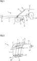
- Fig.1 shows a vehicle 1 using a head-up display 2, in the following also referred to as HUD 2.
- HUD 2 On the left side an engine hood 11 is visible.
- the HUD 2 is arranged below a dashboard 12. Behind the steering wheel 13, the driver's head 14 is shown.
- a windshield 16 Between rooftop 15 and engine hood 11, a windshield 16 is arranged.
- the windshield 16 acts as a transmissive screen 21 of the head-up display 2.
- the HUD 2 generates optical beams L1, which are reflected at the transmissive screen 21 and fall into the driver's eye 141 as long as the eye 141 is within an area called eyebox 24.
- eyebox 24 As long as the eye 141 is within the eyebox 24, the driver sees a virtual image 22 that appears to be outside the vehicle 1 in front of the windshield 16.
- Automotive head-up displays 2 are used to convey critical vehicle information directly in the field of view of the vehicle's conductor or driver.
- the information is delivered to the driver at a certain distance so that no or nearly no accommodation of the driver's eye 141 is required when the driver switches from viewing the road in front of him to reading the vehicle's status shown as the virtual image 22.
- This approach reduces the reaction time of the driver by several hundreds of milliseconds, thus increasing road safety.
- a 300 ms delay translates in a covered distance of about 10 m, which is about 10% of the total stop distance of the vehicle 1.
- the head-up display 2 creates a virtual image 22 ahead of the transmissive screen 21.
- the transmissive screen 21 can be the windshield 16 of the vehicle 1, as shown, or a different, dedicated, partially reflective surface separated from the windshield. Such surface is a so-called combiner.
- the virtual image 22 is visible from a limited region of space only, the so-called eyebox 24.
- Fig.2 shows a head-up display 2 having an image generator 23, also referred to as image projection system below, that generates an optical beam L0.
- the optical beam L0 enters a generic optical system 25, here illustrated by an optical mirror 251, from which an optical beam L1 is directed to the transmissive screen 21.
- a part of the light of beam L1 passes through the transmissive screen 21, which is indicated by dotted arrows. Another part is reflected by the transmissive screen 21 and thus reaches the driver's eye 141 as optical beam L2.
- Fig.3 shows an image projection system as image generator 23 having a light source 231, a diffuser 232, and a display 3, for example a transmissive liquid crystal display (LCD).
- a front polariser 31 is arranged at the front side of the display 3 .
- a back polariser 32 is arranged at the backside of the display 3 .
- the optical beam L0 leaves the image generator 23.
- HUD systems as depicted in Fig.2 and Fig.3 usually consist of an image generator 23 coupled to an optical system 25 that directs the image formed by the image generator 23 onto a transparent screen, the transmissive screen 21.
- the image generator 23 is provided with a backlight unit, the light source 231, which for example uses LEDs, laser beam generators or is of any other type of light source.
- the image generator is further provided with an image forming system that may be a set of sweeping mirrors, micromirror arrays using MEMS technologies or, as shown in Fig.3 , an active matrix liquid crystal display constructed on a flat, rigid glass backplane.
- the essential parts of the image generator 23 for an LCD-based system as illustrated in Fig.3 are, as backlighting source, the light source 231, together with the diffuser 232.
- the diffuser 232 may be a simple diffuser film or a mixed function film like a combination of a diffuser and a brightness enhancing film, the front and back polarising films 31, 32 and an LCD, the image forming display 3.
- Fig.4 shows an image generator 23 of a head-up display 2 according to the invention.
- the image generator 23 is provided with a light source 231, a tilted display 3, a cooling glass 33 and a light trap 34.
- the cooling glass 33 has a wedged shape.
- the optical system 25 and the transmissive screen 21 are not shown here.
- a liquid crystal display 3 is arranged tilted with regard to a main optical axis MOA of the head-up display 2.
- a cooling glass 33 is arranged on the light exiting side of the liquid crystal display 3.
- the cooling glass 33 is shaped as a wedge.
- a diffuser 232 is arranged below the liquid-crystal display 3, on its light incoming side.
- Optical foils 234 are arranged between display 3 and diffuser 232, but not explained in more detail here.
- a lightbox 26 is arranged below the diffuser 232.
- LED light emitting diodes
- lenses 235 are arranged.
- the LEDs as light source 231 are placed on a printed circuit board (PCB) 236.
- the printed circuit board 236 acts as electric insulator between light source 231 and a heatsink 238 as well as a thermal insulator between these.
- the printed circuit board 236 is provided with vias 237 filled with metal or another highly thermally conductive medium in order to transport heat generated by the light source 231 to the heatsink 238.
- Light generated by the light source 231 passes through the lens 235, travels through the lightbox 26 and passes through diffuser 232, optical foils 234 and the liquid display 3.
- An optical beam L0 leaves the liquid-crystal display 3 and passes through the wedge-shaped cooling glass 33 in direction to the generic optical system 25, not shown here.
- Sunlight SL may enter the head-up display 2, mainly if it passes through the windshield 16 parallel to the main optical axis MOA of the head-up display 2. When reaching the cooling glass 33 it is reflected. Due to the inclination of the surface of the cooling glass 33 with respect to the main optical axis MOA, the reflected sunlight SLR is not parallel to the main optical axis MOA and thus does not reach the driver's eye 141 but is absorbed at a light trap 34.
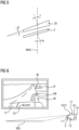
- Fig.5 shows that the display glass 3 is tilted with regard to the main optical axis MOA of the head-up display 2 by a first angle ⁇ .
- the cooling glass 33 has a wedge angle ⁇ with regard to said main optical axis MOA.
- the first angle ⁇ and the wedge angle ⁇ add to an effective tilt angle ⁇ .
- display 3 and display glass 33 are arranged with a distance to each other.
- the wedged display glass 33 is arranged directly on the top layer of the display 3.
- the display glass 33 in this case is affixed to the tilted display 3, e.g. by being glued thereon or bonded thereto in an appropriate manner.
- the display glass 33 is the top layer of the display 3.
- the display glass 33 in this case is the layer of the display 3 that is next to the optically active layer of the display 3.
- Fig.6 shows a schematic side view of the position of a sloped virtual image VBS that is made possible according to the invention as well as an exemplary view that the driver has through the windshield of the vehicle.
- the head-up display 2 has a tilted display 3 and a wedged display glass 33 (both not shown here) according to the invention. Due to the large effective tilt of the display 3, also the virtual image generated therefrom is a sloped virtual image VBS that is nearly parallel to the road surface.
- the optical light beam L1 generated by the head-up display 2 is reflected by the windshield 16 as transmissive screen 21 and reaches the driver's eye 141.
- the driver sees the upper part of the displayed image e.g. at a focal distance of 8m (left part of the sloped virtual image VBS in the figure), and the lower part of the displayed image e.g. at a focal distance of 4m (right part of the sloped virtual image VBS in the figure).
- Fig.6 depicts an exemplary view that the driver has through the windscreen of the vehicle.
- Elements EC, EM, EF of the virtual image are indicated by dashed lines and have partly hashed areas, while real world elements are indicated by continuous lines.
- a current speed (here: 40 km/h) is indicated as close element EC at the lower part of the virtual image. It is visible above the hood (bonnet) 17 of the vehicle and has a focal distance of about 4m.
- a navigation arrow that indicates a suggested turn to the right is indicated as element EM of medium distance in the middle part of the virtual image VBS. It is visible above the road surface 40 at a focal distance of about 6m. At a farther distance a pedestrian 41 is indicated.
- a warning sign is displayed as far element EF. It augments the reality, here: the pedestrian 41, with important information for the driver, here: a warning, e.g. that this pedestrian 41 might cross the road 40.
- the far element EF of the virtual image has a focal distance of about 8m.
- Fig.7 illustrates schematically the effect of the tilt of a display 3, 3-1, 3-2 on the sloped virtual image VBS, VBS-1, VBS-2.
- An optical lens 50 is arranged on a main optical axis MOA.
- the optical lens 50 is a placeholder for all optical elements of the head-up display 2 that are arranged between display 3 and sloped virtual image VBS.
- Display 3-1 is tilted about first angle ⁇ with regard to a plane orthogonal to the main optical axis MOA. Together with the optics indicated here by the optical lens 50 it generates a sloped virtual image VBS-1 that is tilted about an angle ⁇ ' with regard to a plane perpendicular to the main optical axis MOA.
- Another display 3-2 is shown in the figure that is tilted by an angle ⁇ . It generates a sloped virtual image VBS-2 that is tilted about an angle ⁇ '.
- the other display 3-2 and the other sloped virtual VBS-2 are related to each other.
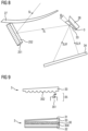
- Fig.8 schematically shows an arrangement according to the invention.
- the display 3 is arranged.
- the wedged display glass 33 is arranged. It has a wedge angle ⁇ .
- an optical mirror 251 is arranged. In the embodiment shown it has an aspheric mirror surface 252.
- a top cover 27 of the head-up display 2 is shown. Sunlight SL passes through the transparent top cover 27 and is reflected by the aspherical mirror surface 252 towards the display glass 33. A part of the sunlight SL is reflected as reflected sunlight SLR on the outer surface of the display glass 33 towards a light trap 34.
- Another part of the sunlight is refracted inside the display glass 33, reflected at its inner surface, refracted when passing its outer surface and directed to the light trap 34 as reflected sunlight SLR'.
- a big amount of sunlight SLR is reflected towards the light trap.
- the remaining sunlight that reaches the display 3 is already dispersed by the prism shape of the wedged display glass 33. It is thus less focussed on the display 3 which prevents small temperature hotspots, but rather leads to temperature blots having a larger area thus causing less heat stress.
- the display glass 33 is arranged as cooling glass that conducts heat away from the display 3, the arrangement shown here has good heat resilience.
- Fig.9 shows two embodiments where the display glass 33 is the layer of the display 3 that is next to the optically active layer 30, 35 of the display 3.
- an LED (Light Emitting Diode) display is shown schematically.
- LEDs 351 are arranged in an LED layer 35, which acts as optically active layer: Only a single LED 351 is shown here for simplicity.
- the LEDs 351 are arranged as matrix. The image is generated by turning on or off LEDs 351 of the matrix.
- the display glass 33 in this embodiment is provided with lenslets 352 at its lower surface. For each LED 351 a lenslet 352 is available to collect the light emitted from the LED 351.
- the display glass 33 has a wedged shape as already described with regard to previous figures.
- the optically active layer is the liquid crystal layer 30 that is sandwiched between a transparent substrate 300 and the wedge-shaped display glass 33. Atop of the display glass 33 a front polarizer 31 is arranged. At the lower surface of the substrate 300 a back polarizer 32 is arranged.
- the invention uses a wedged display cover glass 33 in a head-up display 2.
- a head-up display 2 usually contains a PGU (Picture Generating Unit) which is typically tilted in respect to the Gut Ray or main optical axis MOA to avoid direct sun reflections and/or to control the tilt of the projected virtual image 22.
- PGU Physical Image Generating Unit
- the needed amount of tilting of the real image plane influences negatively the performance of the PGU in terms of efficiency and contrast.
- a cooling glass can be put on the image plane (e.g. onto the light exiting plane of a liquid crystal display according to Thin Film Transistor technology (TFT) or onto a screen on which an image is projected) to improve the sun-load behaviour.
- TFT Thin Film Transistor technology
- This cooling glass is typically flat, has a thickness in the range of 1mm ... 10mm, and is attached to the display or to the image plane.
- the display tilt (in respect to Gut Ray) is reduced by using a wedged cooling glass 33.
- the wedged glass 33 works as a prism or as a laterally shifted lens which refracts the light with an additional angle.
- This approach allows to keep the tilted focus plane used for reflecting sunlight SL onto a light trap 34 by decreasing the effective display tilt.
- This approach can be used for display applications and even for projection type systems where the intermediate plane (screen) represents the image plane.
- This wedged cover glass 33 can be made from different materials like BK7 or even plastic.
Landscapes
- Physics & Mathematics (AREA)
- General Physics & Mathematics (AREA)
- Optics & Photonics (AREA)
- Engineering & Computer Science (AREA)
- Chemical & Material Sciences (AREA)
- Nonlinear Science (AREA)
- Combustion & Propulsion (AREA)
- Transportation (AREA)
- Mechanical Engineering (AREA)
- Mathematical Physics (AREA)
- Crystallography & Structural Chemistry (AREA)
- Instrument Panels (AREA)
Claims (7)
- Afficheur tête haute (2) comportant un générateur d'images (23) avec une source de lumière (231), un afficheur incliné (3), un verre d'affichage (33) et un piège à lumière (34), un système optique (25) et un écran transmissif (21), dans lequel le verre d'affichage (33) a une forme en coin, et le verre d'affichage (33) a un angle de coin (β) par rapport à un axe optique principal (MOA) de l'afficheur tête haute (2), caractérisé en ce que l'afficheur (3) est incliné par rapport audit axe optique principal (MOA) d'un premier angle (α), et dans lequel le premier angle (α) et l'angle de coin (β) augmentent un angle d'inclinaison effectif (γ).
- Afficheur tête haute (2) selon la revendication 1, dans lequel le verre d'affichage est un verre refroidissant (33).
- Afficheur tête haute (2) selon la revendication 2, dans lequel le verre refroidissant (33) conduit la chaleur loin de l'afficheur (3).
- Afficheur tête haute (2) selon l'une quelconque des revendications précédentes, dans lequel le premier angle (α) se situe dans la plage de 10° à 20° et l'angle de coin (β) se situe dans la plage de 10° à 15°.
- Afficheur tête haute (2) selon l'une quelconque des revendications précédentes, dans lequel le verre d'affichage (33) est fixé à l'afficheur incliné (3).
- Afficheur tête haute (2) selon l'une quelconque des revendications 1 à 4, dans lequel le verre d'affichage (33) est la couche de l'afficheur (3) qui est à côté de la couche optiquement active (30, 35) de l'afficheur (3).
- Afficheur tête haute (2) selon l'une quelconque des revendications précédentes, dans lequel le verre d'affichage (33) est constitué de verre BK7 ou est constitué de plastique.
Priority Applications (3)
| Application Number | Priority Date | Filing Date | Title |
|---|---|---|---|
| EP21201662.0A EP4163699B1 (fr) | 2021-10-08 | 2021-10-08 | Affichage tête haute |
| CN202211201197.6A CN115963635A (zh) | 2021-10-08 | 2022-09-29 | 平视显示装置 |
| US17/961,684 US20230115930A1 (en) | 2021-10-08 | 2022-10-07 | Head-up display |
Applications Claiming Priority (1)
| Application Number | Priority Date | Filing Date | Title |
|---|---|---|---|
| EP21201662.0A EP4163699B1 (fr) | 2021-10-08 | 2021-10-08 | Affichage tête haute |
Publications (2)
| Publication Number | Publication Date |
|---|---|
| EP4163699A1 EP4163699A1 (fr) | 2023-04-12 |
| EP4163699B1 true EP4163699B1 (fr) | 2025-06-18 |
Family
ID=78087041
Family Applications (1)
| Application Number | Title | Priority Date | Filing Date |
|---|---|---|---|
| EP21201662.0A Active EP4163699B1 (fr) | 2021-10-08 | 2021-10-08 | Affichage tête haute |
Country Status (3)
| Country | Link |
|---|---|
| US (1) | US20230115930A1 (fr) |
| EP (1) | EP4163699B1 (fr) |
| CN (1) | CN115963635A (fr) |
Families Citing this family (2)
| Publication number | Priority date | Publication date | Assignee | Title |
|---|---|---|---|---|
| JP7767738B2 (ja) * | 2021-06-01 | 2025-11-12 | マツダ株式会社 | ヘッドアップディスプレイ装置 |
| KR20240014266A (ko) * | 2022-07-25 | 2024-02-01 | 현대모비스 주식회사 | 화상형성장치 및 이를 포함하는 헤드업 디스플레이 |
Family Cites Families (17)
| Publication number | Priority date | Publication date | Assignee | Title |
|---|---|---|---|---|
| US5867287A (en) | 1994-09-30 | 1999-02-02 | Hughes Aircraft Company | Head up display with a lens decentered to the optical axis of the illumination |
| DE102008015997B4 (de) * | 2007-03-29 | 2015-09-10 | Denso Corporation | Head-up Display |
| US7690799B2 (en) * | 2008-08-26 | 2010-04-06 | Microvision, Inc. | Optical relay for compact head up display |
| US7854523B2 (en) * | 2008-08-26 | 2010-12-21 | Microvision, Inc. | Optical relay for compact head up display |
| JP2011053386A (ja) | 2009-09-01 | 2011-03-17 | Seiko Epson Corp | 表示装置、電子機器、投射型映像装置 |
| JP5734888B2 (ja) * | 2012-01-31 | 2015-06-17 | 株式会社東芝 | 表示装置、移動体、及び、表示装置の設置方法 |
| JP6200798B2 (ja) * | 2013-12-18 | 2017-09-20 | 株式会社 オルタステクノロジー | 液晶表示装置及びヘッドアップディスプレイ装置 |
| JP6247952B2 (ja) | 2014-02-13 | 2017-12-13 | 株式会社 オルタステクノロジー | ヘッドアップディスプレイ装置 |
| JP6465353B2 (ja) * | 2015-04-28 | 2019-02-06 | 日本精機株式会社 | ヘッドアップディスプレイ装置 |
| JP6547138B2 (ja) * | 2015-12-01 | 2019-07-24 | パナソニックIpマネジメント株式会社 | 自由曲面レンズ、および、ヘッドアップディスプレイ |
| DE102016202464A1 (de) * | 2016-02-18 | 2017-08-24 | Bayerische Motoren Werke Aktiengesellschaft | Projektionsvorrichtung für ein Head-Up-Display, Head-Up-Display sowie Fahrzeug |
| KR102664690B1 (ko) * | 2016-06-02 | 2024-05-09 | 현대모비스 주식회사 | 비대칭 프리즘을 구비한 차량용 헤드업 디스플레이 장치 |
| DE102016112826A1 (de) * | 2016-07-13 | 2018-01-18 | Jabil Optics Germany GmbH | Detektionseinrichtung, HUD und Verfahren zum Betrieb eines HUD |
| JP2018036501A (ja) * | 2016-08-31 | 2018-03-08 | パイオニア株式会社 | 虚像表示装置 |
| JP6709906B2 (ja) * | 2017-03-08 | 2020-06-17 | パナソニックIpマネジメント株式会社 | 画像投写装置 |
| JP2019101056A (ja) * | 2017-11-28 | 2019-06-24 | 株式会社ジャパンディスプレイ | 表示装置およびヘッドアップ表示装置 |
| FR3082630B1 (fr) * | 2018-06-13 | 2020-07-10 | Valeo Comfort And Driving Assistance | Appareil de projection destine a un systeme d'affichage tete haute pour conducteur de vehicule automobile et systeme correspondant |
-
2021
- 2021-10-08 EP EP21201662.0A patent/EP4163699B1/fr active Active
-
2022
- 2022-09-29 CN CN202211201197.6A patent/CN115963635A/zh active Pending
- 2022-10-07 US US17/961,684 patent/US20230115930A1/en active Pending
Also Published As
| Publication number | Publication date |
|---|---|
| CN115963635A (zh) | 2023-04-14 |
| US20230115930A1 (en) | 2023-04-13 |
| EP4163699A1 (fr) | 2023-04-12 |
Similar Documents
| Publication | Publication Date | Title |
|---|---|---|
| JP7698097B2 (ja) | 情報表示装置 | |
| JP7233493B2 (ja) | 情報表示装置 | |
| JP7667843B2 (ja) | 表示装置 | |
| US20250093711A1 (en) | Display, display system, image projection system, and movable object | |
| CN109564350B (zh) | 平视显示装置 | |
| JP7195454B2 (ja) | 光源装置、それを利用した情報表示システムおよびヘッドアップディスプレイ装置 | |
| US12601967B2 (en) | Information display system having acute-angled diffusion characteristics and image light control film used for the same | |
| US10739588B2 (en) | Projection device for a head-up display, head-up display, and vehicle | |
| JPWO2019044072A1 (ja) | 情報表示装置 | |
| JP7587417B2 (ja) | 空間浮遊映像表示装置および光源装置 | |
| US20230115930A1 (en) | Head-up display | |
| JPWO2019064691A1 (ja) | ヘッドアップディスプレイ装置 | |
| US20230113774A1 (en) | Head-up display | |
| WO2020203767A1 (fr) | Système d'affichage d'informations et système d'affichage d'informations de véhicule l'utilisant | |
| JP6982816B2 (ja) | 画像表示装置、虚像表示装置、移動体 | |
| KR102884557B1 (ko) | 이미지 생성 장치 및 헤드-업 디스플레이 | |
| CN116224595B (zh) | 平视显示系统及车辆 | |
| CN222281497U (zh) | 显示元件、显示设备和交通工具 | |
| JP2025018569A (ja) | 光源装置とそれを利用した表示装置 | |
| WO2024190460A1 (fr) | Dispositif de projection d'image |
Legal Events
| Date | Code | Title | Description |
|---|---|---|---|
| PUAI | Public reference made under article 153(3) epc to a published international application that has entered the european phase |
Free format text: ORIGINAL CODE: 0009012 |
|
| STAA | Information on the status of an ep patent application or granted ep patent |
Free format text: STATUS: THE APPLICATION HAS BEEN PUBLISHED |
|
| AK | Designated contracting states |
Kind code of ref document: A1 Designated state(s): AL AT BE BG CH CY CZ DE DK EE ES FI FR GB GR HR HU IE IS IT LI LT LU LV MC MK MT NL NO PL PT RO RS SE SI SK SM TR |
|
| STAA | Information on the status of an ep patent application or granted ep patent |
Free format text: STATUS: REQUEST FOR EXAMINATION WAS MADE |
|
| 17P | Request for examination filed |
Effective date: 20231012 |
|
| RBV | Designated contracting states (corrected) |
Designated state(s): AL AT BE BG CH CY CZ DE DK EE ES FI FR GB GR HR HU IE IS IT LI LT LU LV MC MK MT NL NO PL PT RO RS SE SI SK SM TR |
|
| RAP3 | Party data changed (applicant data changed or rights of an application transferred) |
Owner name: CONTINENTAL AUTOMOTIVE TECHNOLOGIES GMBH |
|
| REG | Reference to a national code |
Ref country code: DE Ref legal event code: R079 Free format text: PREVIOUS MAIN CLASS: G02B0027010000 Ipc: G02B0007000000 Ref country code: DE Ref legal event code: R079 Ref document number: 602021032378 Country of ref document: DE Free format text: PREVIOUS MAIN CLASS: G02B0027010000 Ipc: G02B0007000000 |
|
| GRAP | Despatch of communication of intention to grant a patent |
Free format text: ORIGINAL CODE: EPIDOSNIGR1 |
|
| STAA | Information on the status of an ep patent application or granted ep patent |
Free format text: STATUS: GRANT OF PATENT IS INTENDED |
|
| RIC1 | Information provided on ipc code assigned before grant |
Ipc: B60K 35/60 20240101ALI20250225BHEP Ipc: G02B 27/01 20060101ALI20250225BHEP Ipc: G02B 7/00 20210101AFI20250225BHEP |
|
| INTG | Intention to grant announced |
Effective date: 20250305 |
|
| GRAS | Grant fee paid |
Free format text: ORIGINAL CODE: EPIDOSNIGR3 |
|
| GRAA | (expected) grant |
Free format text: ORIGINAL CODE: 0009210 |
|
| STAA | Information on the status of an ep patent application or granted ep patent |
Free format text: STATUS: THE PATENT HAS BEEN GRANTED |
|
| AK | Designated contracting states |
Kind code of ref document: B1 Designated state(s): AL AT BE BG CH CY CZ DE DK EE ES FI FR GB GR HR HU IE IS IT LI LT LU LV MC MK MT NL NO PL PT RO RS SE SI SK SM TR |
|
| REG | Reference to a national code |
Ref country code: GB Ref legal event code: FG4D |
|
| REG | Reference to a national code |
Ref country code: CH Ref legal event code: EP |
|
| REG | Reference to a national code |
Ref country code: DE Ref legal event code: R096 Ref document number: 602021032378 Country of ref document: DE |
|
| REG | Reference to a national code |
Ref country code: CH Ref legal event code: EP |
|
| REG | Reference to a national code |
Ref country code: IE Ref legal event code: FG4D |
|
| PG25 | Lapsed in a contracting state [announced via postgrant information from national office to epo] |
Ref country code: FI Free format text: LAPSE BECAUSE OF FAILURE TO SUBMIT A TRANSLATION OF THE DESCRIPTION OR TO PAY THE FEE WITHIN THE PRESCRIBED TIME-LIMIT Effective date: 20250618 |
|
| REG | Reference to a national code |
Ref country code: LT Ref legal event code: MG9D |
|
| PG25 | Lapsed in a contracting state [announced via postgrant information from national office to epo] |
Ref country code: NO Free format text: LAPSE BECAUSE OF FAILURE TO SUBMIT A TRANSLATION OF THE DESCRIPTION OR TO PAY THE FEE WITHIN THE PRESCRIBED TIME-LIMIT Effective date: 20250918 Ref country code: GR Free format text: LAPSE BECAUSE OF FAILURE TO SUBMIT A TRANSLATION OF THE DESCRIPTION OR TO PAY THE FEE WITHIN THE PRESCRIBED TIME-LIMIT Effective date: 20250919 |
|
| PG25 | Lapsed in a contracting state [announced via postgrant information from national office to epo] |
Ref country code: BG Free format text: LAPSE BECAUSE OF FAILURE TO SUBMIT A TRANSLATION OF THE DESCRIPTION OR TO PAY THE FEE WITHIN THE PRESCRIBED TIME-LIMIT Effective date: 20250618 |
|
| PG25 | Lapsed in a contracting state [announced via postgrant information from national office to epo] |
Ref country code: HR Free format text: LAPSE BECAUSE OF FAILURE TO SUBMIT A TRANSLATION OF THE DESCRIPTION OR TO PAY THE FEE WITHIN THE PRESCRIBED TIME-LIMIT Effective date: 20250618 |
|
| PG25 | Lapsed in a contracting state [announced via postgrant information from national office to epo] |
Ref country code: RS Free format text: LAPSE BECAUSE OF FAILURE TO SUBMIT A TRANSLATION OF THE DESCRIPTION OR TO PAY THE FEE WITHIN THE PRESCRIBED TIME-LIMIT Effective date: 20250918 |
|
| REG | Reference to a national code |
Ref country code: CH Ref legal event code: W10 Free format text: ST27 STATUS EVENT CODE: U-0-0-W10-W00 (AS PROVIDED BY THE NATIONAL OFFICE) Effective date: 20251022 Ref country code: NL Ref legal event code: MP Effective date: 20250618 |
|
| PG25 | Lapsed in a contracting state [announced via postgrant information from national office to epo] |
Ref country code: LV Free format text: LAPSE BECAUSE OF FAILURE TO SUBMIT A TRANSLATION OF THE DESCRIPTION OR TO PAY THE FEE WITHIN THE PRESCRIBED TIME-LIMIT Effective date: 20250618 |
|
| PG25 | Lapsed in a contracting state [announced via postgrant information from national office to epo] |
Ref country code: NL Free format text: LAPSE BECAUSE OF FAILURE TO SUBMIT A TRANSLATION OF THE DESCRIPTION OR TO PAY THE FEE WITHIN THE PRESCRIBED TIME-LIMIT Effective date: 20250618 |
|
| RAP4 | Party data changed (patent owner data changed or rights of a patent transferred) |
Owner name: AUMOVIO GERMANY GMBH |
|
| PG25 | Lapsed in a contracting state [announced via postgrant information from national office to epo] |
Ref country code: PT Free format text: LAPSE BECAUSE OF FAILURE TO SUBMIT A TRANSLATION OF THE DESCRIPTION OR TO PAY THE FEE WITHIN THE PRESCRIBED TIME-LIMIT Effective date: 20251020 |
|
| REG | Reference to a national code |
Ref country code: AT Ref legal event code: MK05 Ref document number: 1804709 Country of ref document: AT Kind code of ref document: T Effective date: 20250618 |
|
| PG25 | Lapsed in a contracting state [announced via postgrant information from national office to epo] |
Ref country code: IS Free format text: LAPSE BECAUSE OF FAILURE TO SUBMIT A TRANSLATION OF THE DESCRIPTION OR TO PAY THE FEE WITHIN THE PRESCRIBED TIME-LIMIT Effective date: 20251018 |
|
| PGFP | Annual fee paid to national office [announced via postgrant information from national office to epo] |
Ref country code: DE Payment date: 20251031 Year of fee payment: 5 |
|
| PG25 | Lapsed in a contracting state [announced via postgrant information from national office to epo] |
Ref country code: AT Free format text: LAPSE BECAUSE OF FAILURE TO SUBMIT A TRANSLATION OF THE DESCRIPTION OR TO PAY THE FEE WITHIN THE PRESCRIBED TIME-LIMIT Effective date: 20250618 Ref country code: SM Free format text: LAPSE BECAUSE OF FAILURE TO SUBMIT A TRANSLATION OF THE DESCRIPTION OR TO PAY THE FEE WITHIN THE PRESCRIBED TIME-LIMIT Effective date: 20250618 |
|
| PGFP | Annual fee paid to national office [announced via postgrant information from national office to epo] |
Ref country code: FR Payment date: 20251027 Year of fee payment: 5 |
|
| PG25 | Lapsed in a contracting state [announced via postgrant information from national office to epo] |
Ref country code: CZ Free format text: LAPSE BECAUSE OF FAILURE TO SUBMIT A TRANSLATION OF THE DESCRIPTION OR TO PAY THE FEE WITHIN THE PRESCRIBED TIME-LIMIT Effective date: 20250618 |
|
| PG25 | Lapsed in a contracting state [announced via postgrant information from national office to epo] |
Ref country code: PL Free format text: LAPSE BECAUSE OF FAILURE TO SUBMIT A TRANSLATION OF THE DESCRIPTION OR TO PAY THE FEE WITHIN THE PRESCRIBED TIME-LIMIT Effective date: 20250618 |
|
| PG25 | Lapsed in a contracting state [announced via postgrant information from national office to epo] |
Ref country code: EE Free format text: LAPSE BECAUSE OF FAILURE TO SUBMIT A TRANSLATION OF THE DESCRIPTION OR TO PAY THE FEE WITHIN THE PRESCRIBED TIME-LIMIT Effective date: 20250618 |
|
| REG | Reference to a national code |
Ref country code: DE Ref legal event code: R081 Ref document number: 602021032378 Country of ref document: DE Owner name: AUMOVIO GERMANY GMBH, DE Free format text: FORMER OWNER: CONTINENTAL AUTOMOTIVE TECHNOLOGIES GMBH, 30175 HANNOVER, DE |
|
| PG25 | Lapsed in a contracting state [announced via postgrant information from national office to epo] |
Ref country code: SK Free format text: LAPSE BECAUSE OF FAILURE TO SUBMIT A TRANSLATION OF THE DESCRIPTION OR TO PAY THE FEE WITHIN THE PRESCRIBED TIME-LIMIT Effective date: 20250618 |
|
| PGFP | Annual fee paid to national office [announced via postgrant information from national office to epo] |
Ref country code: RO Payment date: 20251003 Year of fee payment: 5 |
|
| PG25 | Lapsed in a contracting state [announced via postgrant information from national office to epo] |
Ref country code: ES Free format text: LAPSE BECAUSE OF FAILURE TO SUBMIT A TRANSLATION OF THE DESCRIPTION OR TO PAY THE FEE WITHIN THE PRESCRIBED TIME-LIMIT Effective date: 20250618 |
|
| REG | Reference to a national code |
Ref country code: DE Ref legal event code: R097 Ref document number: 602021032378 Country of ref document: DE |
|
| PG25 | Lapsed in a contracting state [announced via postgrant information from national office to epo] |
Ref country code: DK Free format text: LAPSE BECAUSE OF FAILURE TO SUBMIT A TRANSLATION OF THE DESCRIPTION OR TO PAY THE FEE WITHIN THE PRESCRIBED TIME-LIMIT Effective date: 20250618 |
|
| PG25 | Lapsed in a contracting state [announced via postgrant information from national office to epo] |
Ref country code: IT Free format text: LAPSE BECAUSE OF FAILURE TO SUBMIT A TRANSLATION OF THE DESCRIPTION OR TO PAY THE FEE WITHIN THE PRESCRIBED TIME-LIMIT Effective date: 20250618 |
|
| PLBE | No opposition filed within time limit |
Free format text: ORIGINAL CODE: 0009261 |
|
| STAA | Information on the status of an ep patent application or granted ep patent |
Free format text: STATUS: NO OPPOSITION FILED WITHIN TIME LIMIT |
|
| REG | Reference to a national code |
Ref country code: CH Ref legal event code: L10 Free format text: ST27 STATUS EVENT CODE: U-0-0-L10-L00 (AS PROVIDED BY THE NATIONAL OFFICE) Effective date: 20260430 |