EP4163742A1 - Procédé de vérification d'un agencement d'accès à l'aide d'un terminal mobile, terminal mobile, système serveur, système, produit-programme informatique - Google Patents
Procédé de vérification d'un agencement d'accès à l'aide d'un terminal mobile, terminal mobile, système serveur, système, produit-programme informatique Download PDFInfo
- Publication number
- EP4163742A1 EP4163742A1 EP21201069.8A EP21201069A EP4163742A1 EP 4163742 A1 EP4163742 A1 EP 4163742A1 EP 21201069 A EP21201069 A EP 21201069A EP 4163742 A1 EP4163742 A1 EP 4163742A1
- Authority
- EP
- European Patent Office
- Prior art keywords
- access device
- measurement data
- mobile terminal
- server system
- configuration information
- Prior art date
- Legal status (The legal status is an assumption and is not a legal conclusion. Google has not performed a legal analysis and makes no representation as to the accuracy of the status listed.)
- Granted
Links
Images


Classifications
-
- G—PHYSICS
- G05—CONTROLLING; REGULATING
- G05B—CONTROL OR REGULATING SYSTEMS IN GENERAL; FUNCTIONAL ELEMENTS OF SUCH SYSTEMS; MONITORING OR TESTING ARRANGEMENTS FOR SUCH SYSTEMS OR ELEMENTS
- G05B19/00—Program-control systems
- G05B19/02—Program-control systems electric
- G05B19/04—Program control other than numerical control, i.e. in sequence controllers or logic controllers
- G05B19/042—Program control other than numerical control, i.e. in sequence controllers or logic controllers using digital processors
-
- G—PHYSICS
- G05—CONTROLLING; REGULATING
- G05B—CONTROL OR REGULATING SYSTEMS IN GENERAL; FUNCTIONAL ELEMENTS OF SUCH SYSTEMS; MONITORING OR TESTING ARRANGEMENTS FOR SUCH SYSTEMS OR ELEMENTS
- G05B2219/00—Program-control systems
- G05B2219/20—Pc systems
- G05B2219/24—Pc safety
- G05B2219/24012—Use camera of handheld device, head mounted display
-
- G—PHYSICS
- G05—CONTROLLING; REGULATING
- G05B—CONTROL OR REGULATING SYSTEMS IN GENERAL; FUNCTIONAL ELEMENTS OF SUCH SYSTEMS; MONITORING OR TESTING ARRANGEMENTS FOR SUCH SYSTEMS OR ELEMENTS
- G05B2219/00—Program-control systems
- G05B2219/20—Pc systems
- G05B2219/24—Pc safety
- G05B2219/24097—Camera monitors controlled machine
-
- G—PHYSICS
- G05—CONTROLLING; REGULATING
- G05B—CONTROL OR REGULATING SYSTEMS IN GENERAL; FUNCTIONAL ELEMENTS OF SUCH SYSTEMS; MONITORING OR TESTING ARRANGEMENTS FOR SUCH SYSTEMS OR ELEMENTS
- G05B2219/00—Program-control systems
- G05B2219/20—Pc systems
- G05B2219/26—Pc applications
- G05B2219/2628—Door, window
-
- G—PHYSICS
- G05—CONTROLLING; REGULATING
- G05B—CONTROL OR REGULATING SYSTEMS IN GENERAL; FUNCTIONAL ELEMENTS OF SUCH SYSTEMS; MONITORING OR TESTING ARRANGEMENTS FOR SUCH SYSTEMS OR ELEMENTS
- G05B2219/00—Program-control systems
- G05B2219/20—Pc systems
- G05B2219/26—Pc applications
- G05B2219/2651—Camera, photo
Definitions
- the present invention relates to a method for checking an access device.
- the invention also relates to a mobile terminal device and a server system.
- the invention relates to a system comprising a mobile terminal device and a server system, as well as a computer program product.
- Access devices are used in or on buildings or areas to control or restrict access to certain areas and rooms and to separate individual areas and rooms from the rest of the building or area.
- Modern access solutions often include a wide range of functions that require electrical control, such as automatic door devices, security functions, alarm functions and lock functions. Therefore, electrical control devices or control devices are often present to control the access devices.
- the access devices and control devices are installed on the basis of plans, with the intended device types being arranged and installed at the intended locations in the building. The commissioning of newly installed access devices and their functional configuration, especially with the help of suitable software, is typically cumbersome as well as time-consuming and costly.
- Tests can be carried out during commissioning and over the life cycle of an access device in which, on the one hand, malfunctions or signs of wear and tear can be identified and, on the other hand, the configuration, in particular the computer-implemented operating parameters, of the access device can be checked, adjusted and adjusted.
- the task is to provide an advantageous method for checking an access device, which preferably enables efficient detection of faults and problems in the access device and/or advantageous setting and configuration of the access device.
- an access device can be advantageously checked using a mobile terminal device.
- the check can be carried out by specialist personnel as well as by an untrained user or operator of the access device, who can use a mobile end device with a measuring device for this purpose.
- a particular advantage of the present invention is the low latency with which the results of the check can be obtained and, if necessary, countermeasures can be initiated.
- an advantageous computer-implemented evaluation and analysis of measurement data is possible using a server system.
- the mobile terminal can be, for example, a mobile phone, in particular a smartphone, a portable computer device, such as for example a tablet computer, or a wearable such as a smartwatch.
- Such mobile terminals typically have measuring devices, such as cameras or microphones, so that the method according to the invention can be carried out in a particularly cost-efficient and user-friendly manner.
- the mobile terminal has an application (app) that configures it to carry out the steps of a method carried out by the mobile terminal according to an embodiment of the present invention.
- instructions for carrying out the method according to the invention and/or results of the analysis in step e) can be displayed or output acoustically to a user of the mobile terminal via the app of the mobile terminal.
- the access device can be checked with the aid of step e).
- the implementation of the analysis in step e) is preferably intended to determine technical problems, faults or signs of wear and tear of the access device.
- step e) is carried out using known reference data, models, machine learning and/or trained artificial intelligence systems that are configured to detect errors, malfunctions and/or signs of wear and tear of the access device in the measurement data. This allows an advantageously automated and computer-implemented data analysis to check the access device.
- test drive relates to one or more access components of the access device.
- the access components of the access device can also be understood as subsystems of the access device.
- the test run is preferably a test run of a separating element and/or door element of the access device.
- the test run preferably includes an opening and/or closing run or at least a partial area of an opening and/or closing run of the separating element and/or door element.
- the test drive is started using the mobile device, for example via an application (app) on the mobile device.
- the mobile terminal transmits a start signal, in particular with the aid of a wireless or wired communication interface, to the access device.
- test drive in step a) is started by a user input on an input means of the access device, for example by releasing a push button.
- one or more test specimens for example one or more wooden blocks, are taken into account during the test drive.
- the test body or bodies to be arranged between a door element and a door frame, so that an emergency stop of the access device is checked and/or tested when closing.
- the test drive in step a) is a learning drive and/or adjustment drive for configuring and/or setting operating parameters of the access device, preferably during installation and/or initial commissioning the access device, is carried out.
- the test drive in step a) is carried out on an access device that has already been installed, in particular after it has been commissioned, in order to check the functions of the access device, identify errors, determine signs of wear and tear and/or configure operating parameters of the access device change.
- the test drive in step a) is carried out at least one month or one year after the installation and/or commissioning of the access device.
- the method according to the invention is in particular a computer-implemented method in which one, several or all steps of the method are executed in a computer-implemented manner.
- the communication connection between the mobile terminal device and the server system is preferably established using a telecommunications network, in particular using a mobile radio network.
- Configuration information using a storage medium for example a USB stick, can be read from the access device and then transmitted to the server system. This is particularly advantageous for access devices that do not have their own connection to a telecommunications network and/or a cloud.
- the access device it is conceivable for the access device to have a control device for a separating element of the access device and/or for a door element of the access device, with the control device for activating the separating element and/or the door element being designed in such a way that the test run in Step a) is carried out.
- the control device can be understood as part of the access device or as a separate element that is connected to the access device and/or the access components of the access device.
- countermeasures can be initiated to correct the identified error or problem, for example hinges can be adjusted, the control of the drive unit of the separating element or door element can be adjusted, or problems with the fit of the door frame can be corrected.
- the initial configuration information relates to a setting of one or more operating parameters of the access device, wherein the one or more operating parameters of the access device are set as a function of the initial configuration information in the previous step.
- the access device can be preconfigured and/or preadjusted in advance on the basis of the initial configuration information. In the test that is then carried out using the test drive and the following steps, the quality of the pre-configuration and/or pre-adjustment can be checked.
- Errors or problems in the preconfiguration and/or preadjustment carried out in the previous step on the basis of the initial configuration information can thus be identified with the aid of steps a) to e).
- the initial configuration information is loaded onto the access device, for example onto a control device of the access device, so that the configuration of the access device is carried out and/or changed automatically.
- the initial configuration information Instructions, in particular graphic and/or acoustic instructions, are reproduced using the mobile device and instruct an installer, a user and/or an operator of the access device to make changes to the access device or its operating parameters or to set the access device or its operating parameters .
- the determination of errors in the access device in step e) includes using the measurement data to carry out a comparison with one or more threshold values.
- the determination of errors in the access device in step e) includes determining an actual deviation between one or more measured values and a norm. In particular, it is considered whether the actual deviation between the one or more measured values is within a target deviation from the norm, with the target deviation corresponding to the norm +/- a tolerance.
- the norm, the tolerance and/or the one or more threshold values are preferably stored in the server system or can be called up by the server system.
- the configuration information relates to a change in one or more operating parameters of the access device, the one or more operating parameters of the access device being changed depending on the configuration information in a step f).
- the configuration information is loaded onto the access device, for example onto a control device of the access device, so that the configuration of the access device is carried out and/or changed automatically.
- the configuration information includes instructions, in particular graphic and/or acoustic instructions, which are reproduced using the mobile terminal device and instruct an installer, a user, and/or an operator of the access device to make changes to the access device or its operating parameters to do.
- the operating parameters of the access device are thus preferably adjusted in accordance with the configuration information in step f).
- the configuration information it is possible for the configuration information to be set up in such a way to change the one or more operating parameters of the access device that an access component of the access device for which wear and tear or a fault was determined in step e) during operation of the access device with the changed operating parameter(s) is spared or less stressed.
- An advantageous, in particular automated, adaptation of the operating parameters of the access device can thus be carried out on the basis of the analysis in step e) in such a way that the error rate of the access device can be reduced and the service life of the access device can be increased. In particular, malfunctions and failures can thus be prevented particularly efficiently.
- step f) after changing one or more operating parameters of the access device in step f) - steps a) to e) or a) to f) are repeated, in particular with this repetition
- Test drive of the access device is carried out in step a) with the one or more changed operating parameters of the access device.
- steps a) to f) it is conceivable for steps a) to f) to be repeated several times until the analysis in step e) shows that a desired and/or selectable target mode of functioning has been achieved. Such iterative optimization can take place during the installation and/or initial commissioning of the access device.
- steps a) to f) are run through with a definable number of repetitions or until the analysis in step e) shows that a quality criterion, in particular a selectable one, is met or a problem or error in the access device has been eliminated.
- the initial configuration information and/or the configuration information is dependent on one or more user profiles of the access device, the one or more user profiles being selected and/or configured in particular depending on the application of the access device, wherein the one or more usage profiles can preferably be selected and/or set by a user or operator of the access device.
- the operating parameters of the access device can thus be optimized for the specific application and the local conditions at the installation site of the access device.
- the one or more user profiles are preferably stored on the server system or at least by the Server system retrievable user profile data.
- the one or more user profiles can be installed by a user or operator of the access device using an interface of the server system, for example using an API (Application Programming Interface), and/or using an installable on the mobile device and/or another device Application (app) are adjustable and / or selectable.
- the one or more usage profiles can be assigned to a digital representation of the access device, with the digital representation of the access device preferably being stored on the server system or being retrievable by the server system.
- a user or operator of the access device can thus undertake an individual configuration of the usage profile or profiles that are assigned to the access device in the server system.
- the user or operator for the access device can make a selection from a plurality of preconfigured user profiles and/or can rank several preconfigured user profiles.
- the usage profiles can be understood as optimization stages with regard to different optimization parameters. In this regard, a large number of different usage profiles are conceivable, which can be individually adapted to the application conditions of the access device.
- the selection of a usage profile which relates to an optimization with regard to energy efficiency of a building or room that can be entered using the access device, can include that a closing movement of a door element or separating element of the access device is carried out particularly quickly in order to reduce the total opening time per opening and closing movement, so that less heat can escape from the building or room.
- the selection of a usage profile that relates to optimization with regard to the service life of the access device can include an opening and/or closing movement of a door element or separating element of the access device being carried out in such a way that hinges and/or a motor of the access device are protected.
- the opening travel and/or closing travel are carried out particularly slowly.
- the selection of a usage profile which relates to an optimization with regard to the speed of the access device and/or the user comfort when using the access device and/or the maximum number of people throughput of the access device, can include that both an opening drive and a closing drive of the access device with an increased Speed are carried out in such a way that the maximum throughput of people is maximized per defined time interval.
- the server system has a digital representation of the access device, with the initial configuration information and/or the configuration information being or being stored as part of the digital representation.
- the measurement data generated in step a) include both optical measurement data and acoustic measurement data, in particular with the optical measurement data and acoustic measurement data being recorded simultaneously in step a), with the access device during the test drive in Step a) outputs an acoustic calibration signal and/or an optical calibration signal, with the acoustic calibration signal and/or the optical calibration signal being used to coordinate the optical and acoustic measurement data with one another, preferably in step b) and/or step e). It is preferred that the access device emits both an optical calibration signal and an acoustic calibration signal, particularly preferably at the same time. A particularly advantageous and comprehensive test can thus be carried out.
- the recorded acoustic and optical measurement data are temporally related to one another, with the acoustic and optical calibration signal being used to determine which acoustic and optical measurement data depict the same point in time during the test drive.
- the identification of the acoustic calibration signal in the acoustic measurement data and the identification of the optical calibration signal in the optical measurement data can thus result in a temporal association between the optical and acoustic measurement data.
- the acoustic and/or optical calibration signal can be output, for example, at a specified time during the test drive and/or at a specified position of the access device during the test drive in step a).
- the acoustic calibration signal is preferably in the inaudible range so that it does not disturb or confuse a user of the mobile terminal device. Alternatively, however, it is conceivable that the acoustic calibration signal is an audible signal. It is conceivable that the acoustic calibration signal is emitted by a loudspeaker in the access device. It is alternatively conceivable that the acoustic calibration signal is an acoustic signal of an access component of the access device, which has a different main function than the output of acoustic signals.
- the acoustic calibration signal can be emitted by a drive unit of the access device, and can include, for example, an intentionally induced motor whirring.
- the optical calibration signal can be output from the access device using a light source, for example a lamp.
- the optical calibration signal can be, for example, a flashing or lighting up of the lamp.
- the light source is part of the drive unit of the access device.
- the optical calibration signal is in the visible or non-visible frequency range.
- the optical calibration signal can be in the infrared range.
- acoustic calibration signal is output by the access device during the test drive.
- the acoustic calibration signal can be output, for example, at a fixed opening angle of a door element or separating element of the access device during the test drive.
- the opening angle can be identified in the optical measurement data, so that an advantageous time coordination between the optical and acoustic measurement data is possible using the acoustic calibration signal.
- a marking element or several marking elements are arranged on the access device, with a detection of a position of the access device in the measurement data, in particular the optical measurement data, using the marking element or the several marking elements, preferably when carrying out the analysis in step e) and/or when processing the recorded measurement data in step b).
- the movement of the access device can be determined particularly advantageously during the test drive.
- the marking element can also help to identify the access device and/or its outlines in a computer-implemented manner in the measurement data in the case of object recognition carried out on the basis of the optical measurement data.
- the marking element can include a reflector, for example, which is used in the recorded optical measurement data as a reference point for determining the movement and/or position of the access device during the test drive.
- Instructions for arranging the marking element on the access device and/or information on an attachment position of the marking element on the access device can be communicated to a user by the mobile device, for example via an optical and/or acoustic output using an application (app) on the mobile device.
- an application application
- a user through an application of the mobile device to arrange a marking element on the access device, for example on a door frame or a movable door element. Since the dimensions of the marking element are known, length dimensions, width dimensions, distances and/or movements of the access device can be determined particularly advantageously in the optical measurement data using the marking element, in particular in step b) and/or step e).
- a sensor device in particular a radar sensor device
- the aid of the sensor device during the test drive in step a) determining further measurement data relating to a position and/or a speed of the access device during the test drive be, with the further measurement data being transmitted to the server system, with the analysis in step e) also being carried out using the further measurement data.
- the sensor device is preferably part of the access device.
- a position, in particular an opening angle, a speed and/or an acceleration of a door element or a separating element of the access device can be determined particularly precisely during the test run.
- a particularly precise and extensive analysis in step e) is possible with the measurement data obtained in this way.
- the sensor device, in particular the radar sensor device can be part of the access device, part of the mobile terminal device, or a device that is separate from the access device and the mobile terminal device.
- the access device has an electrical sensor device, with the electrical sensor device using electrical measurement data relating to an electrical voltage and/or an electrical current of a motor of the access device and/or a control device of the access device during the Test drive are determined in step a), wherein the electrical measurement data are transmitted to the server system, the analysis in step e) is also performed using the electrical measurement data.
- the electrical measurement data are to be understood in particular as measurement data that an electrical voltage and / or a electrical current of a motor of the access device and/or a control device of the access device.
- the electrical measurement data are determined in addition to the acoustic and / or optical measurement data and represent a supplement to the acoustic and / or optical measurement data in the analysis in step e). It is conceivable that the mobile device via a communication interface of the mobile Terminal with the access device and / or the electrical sensor device connects, wherein the electrical measurement data are transmitted from the access device and / or the electrical sensor device to the mobile terminal.
- the mobile terminal then transmits at least some of the electrical measurement data to the server system, so that the electrical measurement data are available to the server system for the analysis in step e).
- the electrical measurement data from the access device and/or the electrical sensor device are transmitted directly to the server system using a corresponding communication interface.
- the electrical sensor device includes an angle sensor of the access device, with the electrical measurement data being recorded using the angle sensor. This is particularly preferred in the case of an access device with one or more wing door drives, which often have such angle sensors anyway.
- the server system carries out an identification of the access device that has carried out step a) using the measurement data received from the server system.
- the access device it is possible for the access device to have an optically recognizable marking, which can be used to identify the access device in the optical measurement data.
- the optical and / or acoustic calibration signal which the access device preferably emits during the test drive, is suitable for identifying the access device. It is thus advantageously possible to dispense with a user of the mobile terminal device having to manually enter identification information for the access device and transmit it to the server system.
- the access device transmits identification information for identifying the access device using a communication interface of the mobile device, for example using WiFi or Bluetooth, to the mobile device, with the mobile device transmitting the identification information to the server system.
- a communication interface of the mobile device for example using WiFi or Bluetooth
- an alignment element for example a frame or an outline of a door frame
- the Alignment element specifies how the mobile device, in particular the optical measuring device, must be aligned in order to record the optical measurement data during the test drive in step b).
- the alignment element can also be understood as a reference pattern displayed on the screen, which instructs the user how the mobile terminal device is to be aligned for measuring the test drive.
- a user of the mobile device is given an ideal location relative to the access device, from which the determination of the Measurement data, in particular the optical measurement data, has to take place during the test drive in step b).
- This ideal location is specified, for example, using a screen on the mobile terminal device and/or using augmented reality. It is conceivable, for example, that the location is specified in such a way that a light signal signals to a user how close the user or the mobile terminal device is to the ideal location for measuring the test drive located.
- the colored signal may appear green in the immediate vicinity of the ideal location and red at too great a distance from the ideal location, particularly above a threshold distance.
- the screen and/or augmented reality can be used to display information about how close the user or the mobile terminal device is to the ideal location.
- the analysis in step e) also includes how far away from the ideal location the mobile terminal device was when generating the measurement data in step b).
- the user of the mobile terminal device is shown a measure of the quality with which the analysis in step e) can be carried out, this measure being dependent on the position of the user or mobile terminal device relative to the ideal location.
- the screen and/or augmented relation can be used to show the user that only a quality of 50% can be delivered at his current position.
- the mobile terminal device it is also conceivable for the mobile terminal device to output an acoustic signal, which alerts a user of the mobile terminal device to the ideal location or his current distance from the ideal location.
- Another subject matter of the present invention is a mobile terminal for checking an access device, the mobile terminal being set up for communication with a server system via a direct or indirect communication link, the mobile terminal having a measuring device, wherein the mobile terminal is configured to perform a method according to an embodiment of the present invention.
- the mobile terminal comprises computing means configured to carry out a method according to an embodiment of the present invention.
- the mobile terminal is used for execution of the steps performed by the mobile terminal of a method according to an embodiment of the present invention.
- Another subject matter of the present invention is a server system for checking an access device, the server system being set up for communication with a mobile terminal device via a direct or indirect communication link, wherein the server system is configured to perform a method according to an embodiment of the present invention.
- the server system comprises computer means configured to carry out a method according to an embodiment of the present invention.
- the server system is configured to carry out the steps performed by the server system of a method according to an embodiment of the present invention.
- the server system is preferably designed as a cloud system.
- Another subject matter of the present invention is a system for checking an access device using a mobile terminal, the system comprising the mobile terminal and a server system, the mobile terminal being set up for communication with the server system via a direct or indirect communication link, wherein the system is configured to perform a method according to an embodiment of the present invention.
- the system preferably also includes the access device.
- Another subject matter of the present invention is a computer program product comprising instructions which, when executed by a mobile terminal device according to an embodiment of the present invention and/or a server system according to an embodiment of the present invention and/or a system according to an embodiment of the present invention, these cause to perform a method according to an embodiment of the present invention.
- FIG.1 1 is shown a system according to an embodiment of the present invention.
- a control device 12 is connected to an access device 10 or is part of the access device 10 educated.
- the control device 12 and the access device 10 can communicate via a wireless and/or wired connection.
- a wired connection in particular a bus system, is preferably implemented between the control device 12 and the access device 10 .
- the control device 12 and the access device 10 are installed in particular in or on a building and/or area. It is possible for the control device 12 and/or the access device 10 to have an electrical sensor device 16 which is designed to measure a current and/or a voltage of a motor of the access device 10 and/or to measure a current and/or a voltage of the control device is.
- the access device 10 includes various access components 10', 10'', 10′′′ (cf. Figure 2A ), for example a door element 11 and a drive unit which is set up to drive the door element 11 .
- the drive unit can in particular be a motor or actuator.
- the control device 12 is configured to control the access device 10, in particular to control a drive unit.
- the access device 10 can also have a large number of other access components 10′, 10′′, 10′′′, for example a hinge, a lock, a security system, a signaling device, a lamp, and so on.
- the mobile terminal 20 includes a measuring device 25.
- the measuring device 25 includes both an optical measuring device 21 and an acoustic measuring device 22, so that the mobile terminal 20 can record both optical measurement data and acoustic measurement data.
- the mobile terminal 20 is typically carried along by a user or operator of the access device 10 or an installer.
- the mobile terminal device 20 can be moved into the vicinity of the access device 10 in order to record measurement data relating to the access device 10 .
- the door element 11 of the access device 10 is designed to carry out a test drive 200 .
- the test drive 200 can, for example, include an opening process and/or a closing process of the door element 11 .
- the test drive 200 is recorded with the aid of the measuring device 25 of the mobile terminal device 20, so that measurement data relating to the test drive 200 are generated.
- a marking element 15 can be arranged on the access device 10, in particular on the door element 11, before the test drive 200 is carried out.
- the marking element 15 can support the identification or localization of the access device 10 in the optical measurement data recorded with the aid of the optical measurement device 21, so that the optical measurement data can be evaluated particularly advantageously by the mobile terminal device 20 and/or the server system 130.
- the mobile terminal device also includes a screen 27 on which optical measurement data recorded using the optical measurement device 21, in particular a video, can be displayed live to a user.
- Fig. 2B 1 shows a mobile terminal 20 according to an embodiment of the present invention.
- an alignment element 28 for example a frame or an outline of a door frame, to be displayed on the screen 27 of the mobile terminal device 20, which specifies how the mobile terminal device 20, in particular the optical measuring device 21, must be aligned in order to record optical measurement data during the test drive 200 in step b) in a particularly advantageous manner.
- the alignment element 28 can in particular also be understood as a reference pattern displayed on the screen 27, which instructs the user how the mobile terminal device 20 Measurement of the test drive 200 is to be aligned.
- the user moves the mobile terminal device 20 before the start of the test drive 200 and/or during the test drive 200 in such a way that the access device 10 is within the alignment element 28 in the video image recorded using the optical measuring device 21 and displayed on the screen 27. This ensures that when the optical measurement data is generated in step b), the access device 10 is actually detected by the optical measurement device 21 .
- the alignment element 28 can be displayed on the screen 27 as part of an application (app) of the mobile terminal device 20 , the application being provided for checking the access device 10 .
- a test drive 200 is carried out by the access device 10.
- the test drive 200 is measured using a measuring device 25 of the mobile terminal device 20, measurement data relating to the test drive 200 being generated.
- step S33 at least part of the measurement data generated in step S32 is transmitted from the mobile terminal 20 to the server system 130.
- the measurement data transmitted in step S33 are received by the server system 130.
- step S35 the server system 130 carries out an analysis based on the measurement data received. This analysis is set up to check the access device 10, in particular to determine errors, problems and signs of wear and tear on the access device 10, which are identified using the measurement data received in step S34 become.
- the analysis in step S35 is carried out, for example, using models, using artificial intelligence and/or using reference data that are available to the server system 130 .
- step S35 it is optionally possible for the analysis in step S35 to also use electrical measurement data relating to a voltage or a current of a drive unit, in particular a motor, of access device 10 and/or a control device 12 of access device 10 during test drive 200 become.
- electrical measurement data can be determined by an electrical sensor device 16 during the test drive and can be transmitted to the server system 130 by the electrical sensor device 16 and/or the access device 10 and/or the mobile terminal device 20 .
- step S35 it is optionally possible for the analysis in step S35 to also use further measurement data, which are determined using a sensor device, for example a radar sensor device, during test drive 200 and relate to a position or speed of the access device during the test drive.
- Such further measurement data can be transmitted to the server system 130 for example from this sensor device and/or the access device 10 and/or the mobile terminal device 20 .
- a schematic representation of a method for checking an access device 10 using a mobile terminal device 20 is shown.
- initial configuration information is transmitted from the server system 130 to the mobile terminal device 20 and/or to the access device 10.
- operating parameters of the access device 10 are set, either manually by a user or automatically by a computer-implemented execution of the Initial Configuration Information.
- a test drive 200 is carried out by the access device 10. During test drive 200, the operating parameters set using the initial configuration information are used.
- the test drive 200 is measured using a measuring device 25 of the mobile terminal device 20, measurement data relating to the test drive 200 being generated.
- the recorded measurement data is processed using the mobile terminal device 20 before the measurement data are transmitted to the server system 130 in step S43.
- step S43 at least part of the measurement data generated in step S42 is transmitted from the mobile terminal 20 to the server system 130.
- the measurement data transmitted in step S43 are received by the server system 130.
- step S45 the server system 130 carries out an analysis based on the received measurement data. This analysis is configured to check the access device 10, in particular to determine errors, problems and signs of wear and tear of the access device 10, which are identified based on the measurement data received in step S44 become.
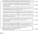
- FIG 5 a schematic representation of a method for checking an access device 10 using a mobile terminal device 20 according to an embodiment of the present invention is shown.
- a step S501 one or more usage profiles 400 are selected and/or set by a user or operator of the access device 10.
- the server system 130 Depending on the selected and/or set usage profiles 400, the server system 130 generates or receives initial configuration information.
- the initial configuration information is transmitted from the server system 130 to the mobile terminal device 20 and/or to the access device 10, the initial configuration information being dependent on the one or more user profiles 400.
- Operating parameters of the access device are set as a function of the transmitted initial configuration information, either manually by a user or automatically by a computer-implemented execution of the initial configuration information.
- a test drive 200 is carried out by the access device 10. During test drive 200, the operating parameters set using the initial configuration information are used.
- a step S52 the test drive 200 is measured using a measuring device 25 of the mobile terminal device 20, measurement data relating to the test drive 200 being generated.
- the recorded measurement data is processed using the mobile terminal device 20 before the measurement data are transmitted to the server system 130 in step S53.
- step S53 at least part of the measurement data generated in step S52 is transmitted from the mobile terminal 20 to the server system 130.
- the measurement data transmitted in step S53 are received by the server system 130.
- the server system 130 carries out an analysis based on the received measurement data. This analysis is configured to check the access device 10, in particular to determine errors, problems and signs of wear and tear of the access device 10, which are identified based on the measurement data received in step S54 become.
- a test drive 200 is carried out by the access device 10.
- the test drive 200 is measured using a measuring device 25 of the mobile terminal device 20, measurement data relating to the test drive 200 being generated.
- the recorded measurement data is processed using the mobile terminal device 20 before the measurement data are transmitted to the server system 130 in step S63.
- step S63 at least part of the measurement data generated in step S62 is transmitted from the mobile terminal 20 to the server system 130.
- the measurement data transmitted in step S63 are received by the server system 130.
- step S65 the server system 130 carries out an analysis based on the received measurement data. This analysis is configured to check the access device 10, in particular to determine errors, problems and signs of wear and tear of the access device 10, which are identified based on the measurement data received in step S64 become.
- configuration information for the access device 10 is generated as a function of the analysis carried out in step S65 by the server system 130. In particular, the configuration information is dependent on problems, errors or signs of wear and tear of the access device 20 determined in step S65, which are necessary for the test drive 200 were found. The configuration information is provided for adjusting the operating parameters of the access device 10 in such a way that the problems, errors or signs of wear and tear determined in step S65 are counteracted or mitigated.
- the configuration information is also dependent on one or more user profiles 400 of the access device 10 that are accessible to the server system 130 .
- the operating parameters for specific applications of an access device 10 can be optimized on the basis of the selected user profile(s) 400, for example to ensure maximum security, the longest possible service life, the highest possible speed, etc.
- step S67 the Configuration information from the server system 130 to the mobile terminal 20 and/or to the access device 10.
- step S68 one or more operating parameters of the access device 10 are changed depending on the configuration information. The change can be made manually by a user or automatically by a computer-implemented execution of the configuration information, for example using a control device 12 of the access device 10.
- step S61 the execution of the test drive 200 is repeated in step S61 with the operating parameter(s) of the access device 10 changed in step S68.
- the further steps S61 to S65 or S61 to S68 are also repeated, preferably until in step S65 in the analysis based on the measurement data received in step S64 a result is obtained which corresponds to selectable quality requirements or represents no improvement over the previous iteration of the method.
- a particularly advantageous iterative optimization of the operating parameters of the access device 10 can thus take place.
- incipient signs of wear and tear, in particular signs of wear, of the access device 10 can be counteracted in a particularly advantageous manner and/or an advantageous adjustment of the operating parameters of the access device 10 to local conditions at the installation site of the access device 10, for example to the room temperature, wind loads, uneven floors etc., take place.
Landscapes
- Physics & Mathematics (AREA)
- General Physics & Mathematics (AREA)
- Engineering & Computer Science (AREA)
- Automation & Control Theory (AREA)
- Mobile Radio Communication Systems (AREA)
- Telephonic Communication Services (AREA)
Priority Applications (3)
| Application Number | Priority Date | Filing Date | Title |
|---|---|---|---|
| EP21201069.8A EP4163742B1 (fr) | 2021-10-05 | 2021-10-05 | Procédé de vérification d'un agencement d'accès à l'aide d'un terminal mobile et système correspondant |
| PL21201069.8T PL4163742T3 (pl) | 2021-10-05 | 2021-10-05 | Sposób testowania urządzenia dostępowego za pomocą terminala mobilnego i odpowiedni system |
| ES21201069T ES2981531T3 (es) | 2021-10-05 | 2021-10-05 | Procedimiento para comprobar un equipo de acceso con ayuda de un terminal móvil y sistema correspondiente |
Applications Claiming Priority (1)
| Application Number | Priority Date | Filing Date | Title |
|---|---|---|---|
| EP21201069.8A EP4163742B1 (fr) | 2021-10-05 | 2021-10-05 | Procédé de vérification d'un agencement d'accès à l'aide d'un terminal mobile et système correspondant |
Publications (3)
| Publication Number | Publication Date |
|---|---|
| EP4163742A1 true EP4163742A1 (fr) | 2023-04-12 |
| EP4163742C0 EP4163742C0 (fr) | 2024-04-17 |
| EP4163742B1 EP4163742B1 (fr) | 2024-04-17 |
Family
ID=78080201
Family Applications (1)
| Application Number | Title | Priority Date | Filing Date |
|---|---|---|---|
| EP21201069.8A Active EP4163742B1 (fr) | 2021-10-05 | 2021-10-05 | Procédé de vérification d'un agencement d'accès à l'aide d'un terminal mobile et système correspondant |
Country Status (3)
| Country | Link |
|---|---|
| EP (1) | EP4163742B1 (fr) |
| ES (1) | ES2981531T3 (fr) |
| PL (1) | PL4163742T3 (fr) |
Cited By (1)
| Publication number | Priority date | Publication date | Assignee | Title |
|---|---|---|---|---|
| WO2025131316A1 (fr) * | 2023-12-22 | 2025-06-26 | Dormakaba Schweiz Ag | Procédé de test d'un appareil d'accès à l'aide d'un dispositif final mobile, dispositif final mobile, système de serveur, système, produit-programme informatique |
Citations (3)
| Publication number | Priority date | Publication date | Assignee | Title |
|---|---|---|---|---|
| US20150370236A1 (en) * | 2013-02-15 | 2015-12-24 | Aktiebolaget Skf | Condition monitoring system and method data exchange |
| US20190193992A1 (en) * | 2016-09-13 | 2019-06-27 | Inventio Ag | Method for monitoring an elevator system |
| US20210032078A1 (en) * | 2018-04-26 | 2021-02-04 | Inventio Ag | Method for monitoring characteristics of a door motion procedure of an elevator door using a smart mobile device |
-
2021
- 2021-10-05 ES ES21201069T patent/ES2981531T3/es active Active
- 2021-10-05 PL PL21201069.8T patent/PL4163742T3/pl unknown
- 2021-10-05 EP EP21201069.8A patent/EP4163742B1/fr active Active
Patent Citations (3)
| Publication number | Priority date | Publication date | Assignee | Title |
|---|---|---|---|---|
| US20150370236A1 (en) * | 2013-02-15 | 2015-12-24 | Aktiebolaget Skf | Condition monitoring system and method data exchange |
| US20190193992A1 (en) * | 2016-09-13 | 2019-06-27 | Inventio Ag | Method for monitoring an elevator system |
| US20210032078A1 (en) * | 2018-04-26 | 2021-02-04 | Inventio Ag | Method for monitoring characteristics of a door motion procedure of an elevator door using a smart mobile device |
Cited By (1)
| Publication number | Priority date | Publication date | Assignee | Title |
|---|---|---|---|---|
| WO2025131316A1 (fr) * | 2023-12-22 | 2025-06-26 | Dormakaba Schweiz Ag | Procédé de test d'un appareil d'accès à l'aide d'un dispositif final mobile, dispositif final mobile, système de serveur, système, produit-programme informatique |
Also Published As
| Publication number | Publication date |
|---|---|
| EP4163742C0 (fr) | 2024-04-17 |
| ES2981531T3 (es) | 2024-10-09 |
| EP4163742B1 (fr) | 2024-04-17 |
| PL4163742T3 (pl) | 2024-07-22 |
Similar Documents
| Publication | Publication Date | Title |
|---|---|---|
| DE60213715T2 (de) | Bildüberwachungsvorrichtung, -verfahren und -verarbeitungsprogramm | |
| EP1956455B1 (fr) | Méthode pour intégrer des noeuds de réseau | |
| EP2996006B1 (fr) | Procede et dispositif de surveillance d'un processus de montage et/ou un processus de fabrication | |
| EP2402827A1 (fr) | Procédé et dispositif pour un contrôle de fonction d'un dispositif de reconnaissance d'objet d'un véhicule automobile | |
| DE102016001920A1 (de) | Steuervorrichtung zum Melden von Wartungs- und Inspektionszeiten signalgesteuerter Peripheriegeräte | |
| EP4163742B1 (fr) | Procédé de vérification d'un agencement d'accès à l'aide d'un terminal mobile et système correspondant | |
| EP4298623A1 (fr) | Procédé de préparation au démarrage d'une unité de commande pour des dispositifs d'accès, système d'accès, unité de commande, dispositif d'accès et produit-programme informatique | |
| DE102017116996B4 (de) | Inbetriebnahme und Konfiguration von mit Anlagen assoziierter Steuerelektronik | |
| EP2160854B1 (fr) | Procédé pour générer une séquence de signaux pouvant être lue sur un testeur pour tester un appareil radioélectrique mobile | |
| EP4202585A1 (fr) | Structure de test et procédé de test d'un appareil de commande | |
| WO2025131316A1 (fr) | Procédé de test d'un appareil d'accès à l'aide d'un dispositif final mobile, dispositif final mobile, système de serveur, système, produit-programme informatique | |
| EP4088551B1 (fr) | Luminaire à auto-test intégré | |
| EP3918882B1 (fr) | Procédé d'assistance à l'installation d'un capteur ou d'un appareil d'éclairage dans des systèmes d'éclairage | |
| EP2879100A1 (fr) | Système doté d'un appareil ménager et d'un dispositif de communication et procédé de fonctionnement d'un tel système | |
| EP3942435A1 (fr) | Rapport numérique de l'état de bâtiments | |
| WO2025119577A1 (fr) | Système d'identification de défauts thermiques sur des objets, procédé d'identification de défauts thermiques sur des objets et support de stockage lisible par ordinateur | |
| DE102013219218A1 (de) | Überwachungsanlage, Verfahren zur Überwachung eines Überwachungsbereichs sowie Computerprogramm | |
| DE102013103851B4 (de) | Verfahren zum Ansteuern von gebäudesystemtechnischen Aktoren | |
| DE102014012624A1 (de) | Vorrichtung und Verfahren zur Detektion fehlerhafter Schraubverbindungen | |
| DE102023119229A1 (de) | Laufzeit-datenerfassung und -überwachung in maschinellen lernsystemen | |
| WO2023066641A1 (fr) | Système et procédé de détermination du statut d'un élément d'une installation | |
| EP4195170A1 (fr) | Procédé de détection d'un dispositif d'accès, procédé d'apprentissage d'un moteur de détection, système serveur, système, produit-programme informatique | |
| DE102004044673A1 (de) | Verfahren und Automatisierungssystem zum Überwachen zumindest einer Anlagenkomponente einer technischen Anlage | |
| EP3877963A1 (fr) | Appareil de commande portatif pour commander un capteur de mouvement | |
| DE102021200192A1 (de) | Verfahren zum Überwachen von Zuständen von Entitäten |
Legal Events
| Date | Code | Title | Description |
|---|---|---|---|
| PUAI | Public reference made under article 153(3) epc to a published international application that has entered the european phase |
Free format text: ORIGINAL CODE: 0009012 |
|
| STAA | Information on the status of an ep patent application or granted ep patent |
Free format text: STATUS: THE APPLICATION HAS BEEN PUBLISHED |
|
| AK | Designated contracting states |
Kind code of ref document: A1 Designated state(s): AL AT BE BG CH CY CZ DE DK EE ES FI FR GB GR HR HU IE IS IT LI LT LU LV MC MK MT NL NO PL PT RO RS SE SI SK SM TR |
|
| STAA | Information on the status of an ep patent application or granted ep patent |
Free format text: STATUS: REQUEST FOR EXAMINATION WAS MADE |
|
| 17P | Request for examination filed |
Effective date: 20231010 |
|
| RBV | Designated contracting states (corrected) |
Designated state(s): AL AT BE BG CH CY CZ DE DK EE ES FI FR GB GR HR HU IE IS IT LI LT LU LV MC MK MT NL NO PL PT RO RS SE SI SK SM TR |
|
| GRAP | Despatch of communication of intention to grant a patent |
Free format text: ORIGINAL CODE: EPIDOSNIGR1 |
|
| STAA | Information on the status of an ep patent application or granted ep patent |
Free format text: STATUS: GRANT OF PATENT IS INTENDED |
|
| INTG | Intention to grant announced |
Effective date: 20231122 |
|
| GRAS | Grant fee paid |
Free format text: ORIGINAL CODE: EPIDOSNIGR3 |
|
| GRAA | (expected) grant |
Free format text: ORIGINAL CODE: 0009210 |
|
| STAA | Information on the status of an ep patent application or granted ep patent |
Free format text: STATUS: THE PATENT HAS BEEN GRANTED |
|
| AK | Designated contracting states |
Kind code of ref document: B1 Designated state(s): AL AT BE BG CH CY CZ DE DK EE ES FI FR GB GR HR HU IE IS IT LI LT LU LV MC MK MT NL NO PL PT RO RS SE SI SK SM TR |
|
| REG | Reference to a national code |
Ref country code: GB Ref legal event code: FG4D Free format text: NOT ENGLISH |
|
| REG | Reference to a national code |
Ref country code: CH Ref legal event code: EP |
|
| REG | Reference to a national code |
Ref country code: IE Ref legal event code: FG4D Free format text: LANGUAGE OF EP DOCUMENT: GERMAN Ref country code: DE Ref legal event code: R096 Ref document number: 502021003370 Country of ref document: DE |
|
| U01 | Request for unitary effect filed |
Effective date: 20240516 |
|
| U07 | Unitary effect registered |
Designated state(s): AT BE BG DE DK EE FI FR IT LT LU LV MT NL PT SE SI Effective date: 20240527 |
|
| PG25 | Lapsed in a contracting state [announced via postgrant information from national office to epo] |
Ref country code: IS Free format text: LAPSE BECAUSE OF FAILURE TO SUBMIT A TRANSLATION OF THE DESCRIPTION OR TO PAY THE FEE WITHIN THE PRESCRIBED TIME-LIMIT Effective date: 20240817 |
|
| REG | Reference to a national code |
Ref country code: ES Ref legal event code: FG2A Ref document number: 2981531 Country of ref document: ES Kind code of ref document: T3 Effective date: 20241009 |
|
| PG25 | Lapsed in a contracting state [announced via postgrant information from national office to epo] |
Ref country code: HR Free format text: LAPSE BECAUSE OF FAILURE TO SUBMIT A TRANSLATION OF THE DESCRIPTION OR TO PAY THE FEE WITHIN THE PRESCRIBED TIME-LIMIT Effective date: 20240417 |
|
| PG25 | Lapsed in a contracting state [announced via postgrant information from national office to epo] |
Ref country code: GR Free format text: LAPSE BECAUSE OF FAILURE TO SUBMIT A TRANSLATION OF THE DESCRIPTION OR TO PAY THE FEE WITHIN THE PRESCRIBED TIME-LIMIT Effective date: 20240718 |
|
| PG25 | Lapsed in a contracting state [announced via postgrant information from national office to epo] |
Ref country code: IS Free format text: LAPSE BECAUSE OF FAILURE TO SUBMIT A TRANSLATION OF THE DESCRIPTION OR TO PAY THE FEE WITHIN THE PRESCRIBED TIME-LIMIT Effective date: 20240817 Ref country code: HR Free format text: LAPSE BECAUSE OF FAILURE TO SUBMIT A TRANSLATION OF THE DESCRIPTION OR TO PAY THE FEE WITHIN THE PRESCRIBED TIME-LIMIT Effective date: 20240417 Ref country code: GR Free format text: LAPSE BECAUSE OF FAILURE TO SUBMIT A TRANSLATION OF THE DESCRIPTION OR TO PAY THE FEE WITHIN THE PRESCRIBED TIME-LIMIT Effective date: 20240718 Ref country code: RS Free format text: LAPSE BECAUSE OF FAILURE TO SUBMIT A TRANSLATION OF THE DESCRIPTION OR TO PAY THE FEE WITHIN THE PRESCRIBED TIME-LIMIT Effective date: 20240717 |
|
| U20 | Renewal fee for the european patent with unitary effect paid |
Year of fee payment: 4 Effective date: 20241025 |
|
| REG | Reference to a national code |
Ref country code: DE Ref legal event code: R097 Ref document number: 502021003370 Country of ref document: DE |
|
| PG25 | Lapsed in a contracting state [announced via postgrant information from national office to epo] |
Ref country code: CZ Free format text: LAPSE BECAUSE OF FAILURE TO SUBMIT A TRANSLATION OF THE DESCRIPTION OR TO PAY THE FEE WITHIN THE PRESCRIBED TIME-LIMIT Effective date: 20240417 |
|
| PG25 | Lapsed in a contracting state [announced via postgrant information from national office to epo] |
Ref country code: SK Free format text: LAPSE BECAUSE OF FAILURE TO SUBMIT A TRANSLATION OF THE DESCRIPTION OR TO PAY THE FEE WITHIN THE PRESCRIBED TIME-LIMIT Effective date: 20240417 Ref country code: RO Free format text: LAPSE BECAUSE OF FAILURE TO SUBMIT A TRANSLATION OF THE DESCRIPTION OR TO PAY THE FEE WITHIN THE PRESCRIBED TIME-LIMIT Effective date: 20240417 |
|
| PG25 | Lapsed in a contracting state [announced via postgrant information from national office to epo] |
Ref country code: SM Free format text: LAPSE BECAUSE OF FAILURE TO SUBMIT A TRANSLATION OF THE DESCRIPTION OR TO PAY THE FEE WITHIN THE PRESCRIBED TIME-LIMIT Effective date: 20240417 |
|
| PG25 | Lapsed in a contracting state [announced via postgrant information from national office to epo] |
Ref country code: SM Free format text: LAPSE BECAUSE OF FAILURE TO SUBMIT A TRANSLATION OF THE DESCRIPTION OR TO PAY THE FEE WITHIN THE PRESCRIBED TIME-LIMIT Effective date: 20240417 Ref country code: SK Free format text: LAPSE BECAUSE OF FAILURE TO SUBMIT A TRANSLATION OF THE DESCRIPTION OR TO PAY THE FEE WITHIN THE PRESCRIBED TIME-LIMIT Effective date: 20240417 Ref country code: RO Free format text: LAPSE BECAUSE OF FAILURE TO SUBMIT A TRANSLATION OF THE DESCRIPTION OR TO PAY THE FEE WITHIN THE PRESCRIBED TIME-LIMIT Effective date: 20240417 Ref country code: CZ Free format text: LAPSE BECAUSE OF FAILURE TO SUBMIT A TRANSLATION OF THE DESCRIPTION OR TO PAY THE FEE WITHIN THE PRESCRIBED TIME-LIMIT Effective date: 20240417 |
|
| PLBE | No opposition filed within time limit |
Free format text: ORIGINAL CODE: 0009261 |
|
| STAA | Information on the status of an ep patent application or granted ep patent |
Free format text: STATUS: NO OPPOSITION FILED WITHIN TIME LIMIT |
|
| 26N | No opposition filed |
Effective date: 20250120 |
|
| PG25 | Lapsed in a contracting state [announced via postgrant information from national office to epo] |
Ref country code: MC Free format text: LAPSE BECAUSE OF FAILURE TO SUBMIT A TRANSLATION OF THE DESCRIPTION OR TO PAY THE FEE WITHIN THE PRESCRIBED TIME-LIMIT Effective date: 20240417 |
|
| PGFP | Annual fee paid to national office [announced via postgrant information from national office to epo] |
Ref country code: PL Payment date: 20250926 Year of fee payment: 5 |
|
| REG | Reference to a national code |
Ref country code: CH Ref legal event code: U11 Free format text: ST27 STATUS EVENT CODE: U-0-0-U10-U11 (AS PROVIDED BY THE NATIONAL OFFICE) Effective date: 20251101 |
|
| U20 | Renewal fee for the european patent with unitary effect paid |
Year of fee payment: 5 Effective date: 20251028 |
|
| PGFP | Annual fee paid to national office [announced via postgrant information from national office to epo] |
Ref country code: GB Payment date: 20251022 Year of fee payment: 5 |
|
| PGFP | Annual fee paid to national office [announced via postgrant information from national office to epo] |
Ref country code: NO Payment date: 20251024 Year of fee payment: 5 |
|
| PGFP | Annual fee paid to national office [announced via postgrant information from national office to epo] |
Ref country code: CH Payment date: 20251101 Year of fee payment: 5 |
|
| PGFP | Annual fee paid to national office [announced via postgrant information from national office to epo] |
Ref country code: IE Payment date: 20251024 Year of fee payment: 5 |
|
| PG25 | Lapsed in a contracting state [announced via postgrant information from national office to epo] |
Ref country code: CY Free format text: LAPSE BECAUSE OF FAILURE TO SUBMIT A TRANSLATION OF THE DESCRIPTION OR TO PAY THE FEE WITHIN THE PRESCRIBED TIME-LIMIT; INVALID AB INITIO Effective date: 20211005 |
|
| PGFP | Annual fee paid to national office [announced via postgrant information from national office to epo] |
Ref country code: ES Payment date: 20251216 Year of fee payment: 5 |
|
| PG25 | Lapsed in a contracting state [announced via postgrant information from national office to epo] |
Ref country code: HU Free format text: LAPSE BECAUSE OF FAILURE TO SUBMIT A TRANSLATION OF THE DESCRIPTION OR TO PAY THE FEE WITHIN THE PRESCRIBED TIME-LIMIT; INVALID AB INITIO Effective date: 20211005 |