EP4163931A1 - Dynamisches hochspannungsunterseekabel - Google Patents
Dynamisches hochspannungsunterseekabel Download PDFInfo
- Publication number
- EP4163931A1 EP4163931A1 EP20948042.5A EP20948042A EP4163931A1 EP 4163931 A1 EP4163931 A1 EP 4163931A1 EP 20948042 A EP20948042 A EP 20948042A EP 4163931 A1 EP4163931 A1 EP 4163931A1
- Authority
- EP
- European Patent Office
- Prior art keywords
- sheath
- submarine cable
- copper sleeve
- layer
- water
- Prior art date
- Legal status (The legal status is an assumption and is not a legal conclusion. Google has not performed a legal analysis and makes no representation as to the accuracy of the status listed.)
- Pending
Links
Images


Classifications
-
- H—ELECTRICITY
- H01—ELECTRIC ELEMENTS
- H01B—CABLES; CONDUCTORS; INSULATORS; SELECTION OF MATERIALS FOR THEIR CONDUCTIVE, INSULATING OR DIELECTRIC PROPERTIES
- H01B9/00—Power cables
- H01B9/02—Power cables with screens or conductive layers, e.g. for avoiding large potential gradients
- H01B9/021—Features relating to screening tape per se
-
- H—ELECTRICITY
- H01—ELECTRIC ELEMENTS
- H01B—CABLES; CONDUCTORS; INSULATORS; SELECTION OF MATERIALS FOR THEIR CONDUCTIVE, INSULATING OR DIELECTRIC PROPERTIES
- H01B7/00—Insulated conductors or cables characterised by their form
- H01B7/14—Submarine cables
-
- H—ELECTRICITY
- H01—ELECTRIC ELEMENTS
- H01B—CABLES; CONDUCTORS; INSULATORS; SELECTION OF MATERIALS FOR THEIR CONDUCTIVE, INSULATING OR DIELECTRIC PROPERTIES
- H01B7/00—Insulated conductors or cables characterised by their form
- H01B7/17—Protection against damage caused by external factors, e.g. sheaths or armouring
- H01B7/18—Protection against damage caused by wear, mechanical force or pressure; Sheaths; Armouring
- H01B7/20—Metal tubes, e.g. lead sheaths
-
- H—ELECTRICITY
- H01—ELECTRIC ELEMENTS
- H01B—CABLES; CONDUCTORS; INSULATORS; SELECTION OF MATERIALS FOR THEIR CONDUCTIVE, INSULATING OR DIELECTRIC PROPERTIES
- H01B7/00—Insulated conductors or cables characterised by their form
- H01B7/17—Protection against damage caused by external factors, e.g. sheaths or armouring
- H01B7/18—Protection against damage caused by wear, mechanical force or pressure; Sheaths; Armouring
- H01B7/22—Metal wires or tapes, e.g. made of steel
- H01B7/226—Helicoidally wound metal wires or tapes
-
- H—ELECTRICITY
- H01—ELECTRIC ELEMENTS
- H01B—CABLES; CONDUCTORS; INSULATORS; SELECTION OF MATERIALS FOR THEIR CONDUCTIVE, INSULATING OR DIELECTRIC PROPERTIES
- H01B7/00—Insulated conductors or cables characterised by their form
- H01B7/17—Protection against damage caused by external factors, e.g. sheaths or armouring
- H01B7/28—Protection against damage caused by moisture, corrosion, chemical attack or weather
- H01B7/282—Preventing penetration of fluid, e.g. water or humidity, into conductor or cable
-
- H—ELECTRICITY
- H01—ELECTRIC ELEMENTS
- H01B—CABLES; CONDUCTORS; INSULATORS; SELECTION OF MATERIALS FOR THEIR CONDUCTIVE, INSULATING OR DIELECTRIC PROPERTIES
- H01B7/00—Insulated conductors or cables characterised by their form
- H01B7/17—Protection against damage caused by external factors, e.g. sheaths or armouring
- H01B7/28—Protection against damage caused by moisture, corrosion, chemical attack or weather
- H01B7/282—Preventing penetration of fluid, e.g. water or humidity, into conductor or cable
- H01B7/2825—Preventing penetration of fluid, e.g. water or humidity, into conductor or cable using a water impermeable sheath
-
- H—ELECTRICITY
- H01—ELECTRIC ELEMENTS
- H01B—CABLES; CONDUCTORS; INSULATORS; SELECTION OF MATERIALS FOR THEIR CONDUCTIVE, INSULATING OR DIELECTRIC PROPERTIES
- H01B7/00—Insulated conductors or cables characterised by their form
- H01B7/17—Protection against damage caused by external factors, e.g. sheaths or armouring
- H01B7/28—Protection against damage caused by moisture, corrosion, chemical attack or weather
- H01B7/282—Preventing penetration of fluid, e.g. water or humidity, into conductor or cable
- H01B7/285—Preventing penetration of fluid, e.g. water or humidity, into conductor or cable by completely or partially filling interstices in the cable
-
- H—ELECTRICITY
- H01—ELECTRIC ELEMENTS
- H01B—CABLES; CONDUCTORS; INSULATORS; SELECTION OF MATERIALS FOR THEIR CONDUCTIVE, INSULATING OR DIELECTRIC PROPERTIES
- H01B9/00—Power cables
- H01B9/006—Constructional features relating to the conductors
-
- H—ELECTRICITY
- H01—ELECTRIC ELEMENTS
- H01B—CABLES; CONDUCTORS; INSULATORS; SELECTION OF MATERIALS FOR THEIR CONDUCTIVE, INSULATING OR DIELECTRIC PROPERTIES
- H01B13/00—Apparatus or processes specially adapted for manufacturing conductors or cables
- H01B13/22—Sheathing; Armouring; Screening; Applying other protective layers
- H01B13/221—Sheathing; Armouring; Screening; Applying other protective layers filling-up interstices
-
- H—ELECTRICITY
- H01—ELECTRIC ELEMENTS
- H01B—CABLES; CONDUCTORS; INSULATORS; SELECTION OF MATERIALS FOR THEIR CONDUCTIVE, INSULATING OR DIELECTRIC PROPERTIES
- H01B7/00—Insulated conductors or cables characterised by their form
- H01B7/17—Protection against damage caused by external factors, e.g. sheaths or armouring
- H01B7/18—Protection against damage caused by wear, mechanical force or pressure; Sheaths; Armouring
- H01B7/187—Sheaths comprising extruded non-metallic layers
-
- H—ELECTRICITY
- H01—ELECTRIC ELEMENTS
- H01B—CABLES; CONDUCTORS; INSULATORS; SELECTION OF MATERIALS FOR THEIR CONDUCTIVE, INSULATING OR DIELECTRIC PROPERTIES
- H01B7/00—Insulated conductors or cables characterised by their form
- H01B7/32—Insulated conductors or cables characterised by their form with arrangements for indicating defects, e.g. breaks or leaks
-
- H—ELECTRICITY
- H01—ELECTRIC ELEMENTS
- H01B—CABLES; CONDUCTORS; INSULATORS; SELECTION OF MATERIALS FOR THEIR CONDUCTIVE, INSULATING OR DIELECTRIC PROPERTIES
- H01B9/00—Power cables
- H01B9/005—Power cables including optical transmission elements
Definitions
- the present application relates to the technical field of submarine cables, particularly, relates to a high-voltage dynamic submarine cable.
- Floating wind farm must adopt floating booster station for long-distance power transmission.
- the AC voltage transmitted by the booster station is often greater than 110kV, and 220kV becomes the first choice of the AC voltage.
- dynamic submarine cable adopts a wet structure in prior art, that is, water tree resistant insulation material of the dynamic submarine cable can operate in a water vapor environment for a long time.
- water tree resistant insulation materials are generally applied at a dynamic submarine cable carried with an AC voltage below 72kV.
- 110kV and above voltage levels are applied for dynamic submarine cables, insulation materials have become a design bottleneck. According to public information, the high-voltage dynamic submarine cable is still a technical blank.
- an insulation core In design of high-voltage land cable, an insulation core often adopts technologies such as extruded lead sheath, longitudinal wrapping welding aluminum sheath, and the highest voltage level of the high-voltage land cable can reach 500kV.
- these metal sheathing materials in the high-voltage land cable are thick and heavy, not suitable for deep water environment, and have poor fatigue resistance.
- an outer diameter of high-voltage dynamic submarine cable is often more than 200mm after cabling, which brings great challenges to the armoring process and the extrusion capacity of the outer sheath.
- a purpose of the disclosure is to provide a high-voltage dynamic submarine cable that can be used in deep-sea, high salinity and high water pressure environments.
- a high-voltage dynamic submarine cable including an electric unit, an optical unit, a filling strip, an inner sheath, an armor layer, and an outer sheath.
- the electric unit, the optical unit, and the filling strip are intertwisted to form a submarine cable core.
- the submarine cable core is wrapped with the inner sheath and the outer sheath.
- the armor layer is arranged between the inner sheath and the outer sheath.
- the electric unit includes a conductor, a co-extrusion structure layer, a water-blocking buffer layer, a corrugated copper sleeve and a split-phase sheath are sequentially wrapped outside the conductor.
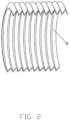
- a plurality of annular or threaded relief structures are rolled on an outer side face of the corrugated copper sleeve in an axial direction.
- the water-blocking buffer layer and the split-phase sheath are in contact with and fill the relief structures on the corrugated copper sleeve.
- a thickness of the corrugated copper sleeve is 0.6-0.8mm
- an inner diameter of the corrugated copper sleeve is 70 ⁇ 150mm
- a pitch of the corrugated copper sleeve is 8 ⁇ 18mm
- a depth of the relief structures is 3 ⁇ 8mm
- when the relief structures are in threaded structures a spiral rise angle of the relief structure is 5 ° ⁇ 60 °.
- the corrugated copper sleeve needs to be annealed, and the material of the corrugated copper sleeve includes but is not limited to at least one of copper and copper alloy.
- the coextrusion structure layer is composed of a conductor shield layer, an insulation layer and an insulation shield layer.
- the co-extrusion structure layer is wrapped with two or four layers of semi conductive water blocking tapes or semi conductive buffer water blocking tapes to form the water-blocking buffer layer.
- copper wires are also arranged between layers of the water blocking buffer layer, and the copper wires are wound in a circumferential direction between the adjacent semi conductive water blocking tapes or semi conductive buffer water blocking taps, quantity of the copper wires is 4-6.
- the split-phase sheath is an extruded phase separation sheath with a thickness of 3 ⁇ 8mm.
- the material of the extruded phase separation sheath is a semiconducting material, including but not limited to at least one of polyethylene and polyurethane.
- the filling strip includes at least one steel strand filling strip and at least one polyethylene filling strip
- the steel strand filling strip includes a plurality of steel strands and a polyethylene sheath
- the plurality of the steel strands are twisted in a strip shape
- the polyethylene sheath is wrapped on the exterior of the plurality of the steel strands
- a plurality of the steel strand filling strips and the polyethylene filling strips are filled in gaps between the optical unit, the electrical unit, and the inner sheath.
- the armor layer is formed by wrapping a plurality of flat steel wires in the form of surface contact.
- the number of layers of the armor layers is even and at least two.
- Each layer of the armor layers is coated with at least one of asphalt, ointment, lubricant and graphene.
- the present disclosure adopts the longitudinal corrugated copper sleeve as the metal shielding layer, which has functions of carrying the short circuit current and radial water resistance, and meets requirements of dynamic state.
- Water blocking can be achieved by setting multi-layer water blocking buffer layers.
- the short circuit current can be shared through the circumferential sparse winding of copper wires between two water blocking buffer layers.
- the extruded split-phase sheath can fill the gaps of the relief structures of the corrugated copper sleeve, achieving the longitudinal water blocking and improve the strength.
- the introduction of optical unit can achieved online monitoring and fault location of dynamic submarine cable temperature and vibration.
- the outer diameter of the high-voltage dynamic submarine cable after cabling can be greatly reduced, and the bending strength and axial tensile strength of the high-voltage submarine cable can be improved, which is convenient for transportation and construction.
- the submarine cable has an excellent radial water blocking effect, guarantees normal use of an ultra-clean high-voltage insulating material in deep and far-sea, high-salinity and high-water-pressure environments, provides guarantee for reliable operation of a floating booster station of future floating wind fields, and guarantees the use function of the high-voltage dynamic submarine cable.
- a high-voltage dynamic submarine cable includes an electric unit, an optical unit 8, a filling strip, an inner sheath 9, an armor layer 10 and an outer sheath 11.
- the electric unit, the optical unit 8, and the filling strip are intertwisted to form a submarine cable core.
- the submarine cable core is wrapped with the inner sheath 9 and the outer sheath 11.
- the armor layer 10 is arranged between the inner sheath 9 and the outer sheath 11.
- the number of the electrical units is at least three.
- the number of optical units 8 is not less than one, which is used to transmit optical signals, and can achieve dynamic detection of submarine cables by monitoring temperature, vibration and other signals. Once the submarine cables are damaged or failed, optical units can quickly alarm and locate.
- Each of the electric unit includes a conductor 1.
- a sectional area of the conductor 1 is not less than 500 mm 2 .
- a co-extrusion structure layer 2, a water-blocking buffer layer 3, a corrugated copper sleeve 4, and a split-phase sheath 5 are sequentially wrapped outside the conductor 1.
- the co-extruded structure layer 2 includes conductor shielding layer, insulating layer, and insulating shielding layer.
- the exterior part of the co-extruded structure layer 2 is wrapped with two or four layers of semi conductive water blocking tapes or semi conductive buffer water blocking tapes to form the water-blocking buffer layer 3.
- the corrugated copper sleeve 4 is sleeved on the exterior part of water blocking buffer layer 3 is sleeved.
- the corrugated copper sleeve 4 will compress the adjacent water blocking buffer layer 3 during rolling.
- the water blocking buffer layer 3 includes a water blocking layer and a buffer layer arranged in sequence.
- the corrugated copper sleeve 4 compresses the water blocking layer to achieve a longitudinal water blocking effect, and the buffer layer relieves indentation of the insulation layer caused by relief structures of the corrugated copper sleeve 4 to ensure the safety of electrical operation.
- copper wires are also arranged between layers of the water blocking buffer layer 3. Specifically, 4-6 copper wires with a diameter of 0.8mm are used to be wound in a circumferential direction between adjacent semi conductive water blocking tapes or semi conductive buffer water blocking tapes.
- a plurality of annular or threaded relief structures are rolled on an outer side face of the corrugated copper sleeve 4 in an axial direction.
- the water-blocking buffer layer 3 and the split-phase sheath 5 are in contact with and filled with the relief structures on the corrugated copper sleeve 4.
- a thickness of corrugated copper sleeve 4 is 0.6-0.8mm
- an inner diameter of the corrugated copper sleeve 4 is 70 ⁇ 150mm
- a pitch of the corrugated copper sleeve 4 is 8 ⁇ 18mm
- a depth of the relief structures is 3 ⁇ 8mm.
- a plurality of annular relief structures is rolled on the outer side face of the corrugated copper sleeve 4 in the axial direction.
- the inner diameter of the corrugated copper sleeve 4 is 70 ⁇ 150mm, and the pitch of the corrugated copper sleeve 4 is 8 ⁇ 18mm, a depth of the relief structures is 3 ⁇ 8mm.
- the submarine cable of the present disclosure can adapt to requirements of cable cores with different section areas, overcome problems of argon arc welding and rolling lines under the conditions of large size, thin wall thickness and continuous length, and avoid defects such as broken welding and missing welding.
- the annular relief structure of the disclosure is beneficial to improve the fatigue strength and fatigue life of the corrugated copper sleeve 4, and the corrugated copper sleeve 4 can also play a role of metal shielding and radial water blocking.
- the inner diameter D1 of the corrugated copper sleeve 4 is 70mm, the pitch of the corrugated copper sleeve 4 is 8 ⁇ 10mm, and the depth of the relief structures is 3 ⁇ 4mm.
- the inner diameter D1 of corrugated copper sleeve 4 is 90mm, the pitch of the corrugated copper sleeve 4 is 10 ⁇ 12mm, and the depth of the relief structures is 4 ⁇ 5mm.
- the inner diameter D1 of the corrugated copper sleeve 4 is 110mm, the pitch of the corrugated copper sleeve 4 is 12 ⁇ 14mm, and the depth of the relief structures is 5 ⁇ 6mm.
- the inner diameter D1 of corrugated copper sleeve 4 is 130mm, the pitch of the corrugated copper sleeve 4 is 14 ⁇ 16mm, and the depth of the relief structures is 6 ⁇ 7mm.
- the inner diameter D1 of corrugated copper sleeve 4 is 150 mm, the pitch of the corrugated copper sleeve 4 is 16 ⁇ 18 mm, and the depth of the relief structures is 7 ⁇ 8 mm.
- a spiral rise angle of the relief structure is 5 ° ⁇ 60 °.
- the material of corrugated copper sleeve 4 includes but is not limited to at least one of copper and copper alloy.
- the copper alloy materials can effectively improve the welding performance during argon arc welding, and significantly improve the fatigue performance and fatigue life of the corrugated copper sleeve 4.
- the corrugated copper sleeve 4 has strain hardening problem after rolling. In order to reduce or eliminate strain hardening and improve the fatigue resistance of the material, the corrugated copper sleeve 4 needs to be annealed by appropriate annealing methods.
- the split-phase sheath 5 of the disclosure adopts an extrusion process, so that gaps of the relief structures on the outer face of the corrugated copper sleeve 4 can be filled.
- a thickness of split-phase sheath 5 is 3 ⁇ 8mm.
- Material of the split-phase sheath 5 is semi conductive material, including but not limited to at least one of polyethylene and polyurethane. The material selection of the split-phase sheath 5 can meet the mechanical protection and grounding effects of corrugated copper sleeve 4.
- the filing strip includes at least one of steel strand filling strip 6 and at least one of polyethylene filling strips 7.
- the steel strand filling strip 6 include a plurality of steel strands and a polyethylene sheath. The plurality of steel strands are twisted in a strip shape, and the polyethylene sheath is wrapped on the exterior of the plurality of the steel strands. A plurality of steel strand filling strips and polyethylene filling strips are filled in gaps between the optical unit 8, the electrical unit, and the inner sheath 9.
- each armor layer 10 is coated with at least one of asphalt, ointment, lubricant and graphene.
- the armor layer 10 of the disclosure can reduce an overall outer diameter of the dynamic submarine cable, improve a bending stiffness of the submarine cable to 5.0 ⁇ 10 5 N ⁇ mm 2 , effectively reduce the number of steel wires, and improve an axial tensile strength of the submarine cable to 1500MN.
- the reduction of the outer diameter of the submarine cable is also conducive to transportation and construction.
Landscapes
- Insulated Conductors (AREA)
Applications Claiming Priority (2)
| Application Number | Priority Date | Filing Date | Title |
|---|---|---|---|
| CN202010772564.2A CN111883310B (zh) | 2020-08-04 | 2020-08-04 | 一种高压动态海缆 |
| PCT/CN2020/126858 WO2022027849A1 (zh) | 2020-08-04 | 2020-11-05 | 一种高压动态海缆 |
Publications (2)
| Publication Number | Publication Date |
|---|---|
| EP4163931A1 true EP4163931A1 (de) | 2023-04-12 |
| EP4163931A4 EP4163931A4 (de) | 2024-06-05 |
Family
ID=73211549
Family Applications (1)
| Application Number | Title | Priority Date | Filing Date |
|---|---|---|---|
| EP20948042.5A Pending EP4163931A4 (de) | 2020-08-04 | 2020-11-05 | Dynamisches hochspannungsunterseekabel |
Country Status (3)
| Country | Link |
|---|---|
| EP (1) | EP4163931A4 (de) |
| CN (1) | CN111883310B (de) |
| WO (1) | WO2022027849A1 (de) |
Families Citing this family (12)
| Publication number | Priority date | Publication date | Assignee | Title |
|---|---|---|---|---|
| CN111883310B (zh) * | 2020-08-04 | 2021-11-23 | 中天科技海缆股份有限公司 | 一种高压动态海缆 |
| CN113031179B (zh) * | 2021-03-22 | 2022-09-16 | 杭州富通通信技术股份有限公司 | 内置阻水节及半干式光缆 |
| CN114005583A (zh) * | 2021-11-01 | 2022-02-01 | 中天科技海缆股份有限公司 | 一种海缆 |
| CN114512270B (zh) * | 2022-03-08 | 2023-06-13 | 安徽渡江电缆集团有限公司 | 一种分层绝缘绞合导体的电力电缆 |
| CN114974676A (zh) * | 2022-06-30 | 2022-08-30 | 中天科技海缆股份有限公司 | 动态海底电缆及动态海底电缆的成型方法 |
| CN115598783A (zh) * | 2022-10-28 | 2023-01-13 | 深圳新澳科电缆有限公司(Cn) | 半硬质高抗压光缆 |
| CN115910443A (zh) * | 2022-11-23 | 2023-04-04 | 国网浙江省电力有限公司舟山供电公司 | 一种具有防震结构层的高压电缆 |
| CN116013598B (zh) * | 2023-01-30 | 2023-09-08 | 佛山市粤佳信电线电缆有限公司 | 一种稳相电缆用环形皱纹铝合金管及其制备工艺 |
| EP4425728A1 (de) * | 2023-02-28 | 2024-09-04 | NKT HV Cables AB | Dynamisches unterwasserstromkabelsystem mit biegungsbegrenzungsvorrichtung |
| CN116665965A (zh) * | 2023-06-25 | 2023-08-29 | 安徽天康集团数据线缆有限公司 | 一种机车用于传输数据的数据电缆 |
| CN117153495B (zh) * | 2023-10-20 | 2024-02-09 | 江苏亨通高压海缆有限公司 | 一种海底电缆阻水胶涂覆设备 |
| CN118549763A (zh) * | 2024-05-21 | 2024-08-27 | 南通贝卡迪电力科技有限公司 | 一种海上风电35kv海缆耐压试验装置及使用方法 |
Family Cites Families (14)
| Publication number | Priority date | Publication date | Assignee | Title |
|---|---|---|---|---|
| FR2407557A1 (fr) * | 1977-10-27 | 1979-05-25 | Cables De Lyon Geoffroy Delore | Cable d'energie etanche et machine pour le fabriquer |
| FR2505082A1 (fr) * | 1981-04-30 | 1982-11-05 | Cables De Lyon Geoffroy Delore | Materiau de bourrage semi-conducteur pour cable sous-marin, cable comportant ce materiau et procede de fabrication de ce cable |
| JP2002100244A (ja) * | 2000-09-26 | 2002-04-05 | Okinawa Electric Power Co Ltd | 二重鎧装海底ケーブル及びその布設方法 |
| NO2750144T3 (de) * | 2011-08-23 | 2018-01-06 | ||
| GB2505660B (en) * | 2012-09-05 | 2014-12-03 | Bpp Cables Ltd | Subsea cables |
| CN103903788A (zh) * | 2014-03-04 | 2014-07-02 | 成都科创佳思科技有限公司 | 高压交联聚乙烯绝缘电力电缆 |
| CN205722889U (zh) * | 2016-05-09 | 2016-11-23 | 万达集团股份有限公司 | 一种浮式平台用动态光电复合海缆 |
| CN206194394U (zh) * | 2016-11-15 | 2017-05-24 | 中天科技海缆有限公司 | 光电复合电缆及其电缆单元 |
| CN106782799B (zh) * | 2016-12-28 | 2018-12-07 | 广州南洋电缆有限公司 | 皱纹铜套皱纹钢套钢丝铠装海底电缆 |
| CN108899114A (zh) * | 2018-08-10 | 2018-11-27 | 中天科技海缆有限公司 | 66kV交联聚乙烯绝缘轻型交流光纤复合海底电缆 |
| CN208938680U (zh) * | 2018-09-20 | 2019-06-04 | 安徽神华特种线缆有限公司 | 防火型柔直线缆 |
| CN209657869U (zh) * | 2019-05-22 | 2019-11-19 | 中天科技海缆有限公司 | 高压电缆 |
| CN211087965U (zh) * | 2019-11-28 | 2020-07-24 | 人民电缆集团有限公司 | 纵向防水电力电缆 |
| CN111883310B (zh) * | 2020-08-04 | 2021-11-23 | 中天科技海缆股份有限公司 | 一种高压动态海缆 |
-
2020
- 2020-08-04 CN CN202010772564.2A patent/CN111883310B/zh active Active
- 2020-11-05 EP EP20948042.5A patent/EP4163931A4/de active Pending
- 2020-11-05 WO PCT/CN2020/126858 patent/WO2022027849A1/zh not_active Ceased
Also Published As
| Publication number | Publication date |
|---|---|
| WO2022027849A1 (zh) | 2022-02-10 |
| EP4163931A4 (de) | 2024-06-05 |
| CN111883310A (zh) | 2020-11-03 |
| CN111883310B (zh) | 2021-11-23 |
Similar Documents
| Publication | Publication Date | Title |
|---|---|---|
| CN111883310B (zh) | 一种高压动态海缆 | |
| CN103000292B (zh) | 超高压交联聚乙烯绝缘柔性直流光纤复合海底电缆 | |
| EP4394804A1 (de) | Dynamisches unterwasserkabel und herstellungsverfahren für dynamisches unterwasserkabel | |
| CN105761828B (zh) | 一种额定电压220kV两芯光电复合海底电缆 | |
| CN101728012A (zh) | 铠装电缆 | |
| CN201590277U (zh) | 铠装电缆 | |
| CN111243787A (zh) | 集束海底电缆及其制备方法 | |
| CN211604786U (zh) | 一种超柔大电流脉冲功率电力电缆 | |
| CN219497407U (zh) | 抑制扭转断线型直流油浸纸高压电缆 | |
| CN216250059U (zh) | 一种高压直流输电系统金属回流线缆 | |
| CN213635499U (zh) | 一种新型耐腐蚀防白蚁高压电缆 | |
| CN214956123U (zh) | 一种中压防水电力电缆 | |
| CN216772894U (zh) | 全屏蔽阻水抗拉耐腐蚀电缆 | |
| CN116779217A (zh) | 阻水型型线绞合电力电缆 | |
| CN209625904U (zh) | 一种耐泥浆石油平台用中压电力电缆 | |
| CN223155690U (zh) | 一种高压单芯动态海底电缆 | |
| CN209880223U (zh) | 一种自承重电力电缆 | |
| CN219246412U (zh) | 一种耐热高强度铝合金电缆 | |
| CN220041414U (zh) | 一种扁金属丝铠装防水中压电缆 | |
| CN220208579U (zh) | 一种新型船用中压变频电缆 | |
| CN223552284U (zh) | 一种抗拉能力强的电缆 | |
| CN111816347A (zh) | 一种0.6/1kv耐盐雾控制电缆及制作工艺 | |
| CN220895243U (zh) | 一种高性能中压电力电缆 | |
| CN224177132U (zh) | 一种新型高性能带铠装阻燃耐火中压电缆 | |
| CN206401055U (zh) | 一种利于保护绝缘层的异型导体绞合电缆 |
Legal Events
| Date | Code | Title | Description |
|---|---|---|---|
| STAA | Information on the status of an ep patent application or granted ep patent |
Free format text: STATUS: THE INTERNATIONAL PUBLICATION HAS BEEN MADE |
|
| PUAI | Public reference made under article 153(3) epc to a published international application that has entered the european phase |
Free format text: ORIGINAL CODE: 0009012 |
|
| STAA | Information on the status of an ep patent application or granted ep patent |
Free format text: STATUS: REQUEST FOR EXAMINATION WAS MADE |
|
| 17P | Request for examination filed |
Effective date: 20230105 |
|
| AK | Designated contracting states |
Kind code of ref document: A1 Designated state(s): AL AT BE BG CH CY CZ DE DK EE ES FI FR GB GR HR HU IE IS IT LI LT LU LV MC MK MT NL NO PL PT RO RS SE SI SK SM TR |
|
| DAV | Request for validation of the european patent (deleted) | ||
| DAX | Request for extension of the european patent (deleted) | ||
| A4 | Supplementary search report drawn up and despatched |
Effective date: 20240508 |
|
| RIC1 | Information provided on ipc code assigned before grant |
Ipc: H01B 13/22 20060101ALN20240502BHEP Ipc: H01B 9/00 20060101ALN20240502BHEP Ipc: H01B 7/285 20060101ALN20240502BHEP Ipc: H01B 7/32 20060101ALN20240502BHEP Ipc: H01B 7/22 20060101ALN20240502BHEP Ipc: H01B 7/18 20060101ALN20240502BHEP Ipc: H01B 7/20 20060101ALI20240502BHEP Ipc: H01B 7/282 20060101ALI20240502BHEP Ipc: H01B 7/14 20060101AFI20240502BHEP |
|
| STAA | Information on the status of an ep patent application or granted ep patent |
Free format text: STATUS: EXAMINATION IS IN PROGRESS |
|
| 17Q | First examination report despatched |
Effective date: 20250903 |