EP4164067A1 - Prise de connexion pour un réseau de données ou de communication - Google Patents
Prise de connexion pour un réseau de données ou de communication Download PDFInfo
- Publication number
- EP4164067A1 EP4164067A1 EP22189696.2A EP22189696A EP4164067A1 EP 4164067 A1 EP4164067 A1 EP 4164067A1 EP 22189696 A EP22189696 A EP 22189696A EP 4164067 A1 EP4164067 A1 EP 4164067A1
- Authority
- EP
- European Patent Office
- Prior art keywords
- bearing surface
- cable
- housing part
- clamping device
- lower housing
- Prior art date
- Legal status (The legal status is an assumption and is not a legal conclusion. Google has not performed a legal analysis and makes no representation as to the accuracy of the status listed.)
- Granted
Links
Images







Classifications
-
- H—ELECTRICITY
- H01—ELECTRIC ELEMENTS
- H01R—ELECTRICALLY-CONDUCTIVE CONNECTIONS; STRUCTURAL ASSOCIATIONS OF A PLURALITY OF MUTUALLY-INSULATED ELECTRICAL CONNECTING ELEMENTS; COUPLING DEVICES; CURRENT COLLECTORS
- H01R13/00—Details of coupling devices of the kinds covered by groups H01R12/70 or H01R24/00 - H01R33/00
- H01R13/58—Means for relieving strain on wire connection, e.g. cord grip, for avoiding loosening of connections between wires and terminals within a coupling device terminating a cable
- H01R13/5841—Means for relieving strain on wire connection, e.g. cord grip, for avoiding loosening of connections between wires and terminals within a coupling device terminating a cable allowing different orientations of the cable with respect to the coupling direction
-
- H—ELECTRICITY
- H01—ELECTRIC ELEMENTS
- H01R—ELECTRICALLY-CONDUCTIVE CONNECTIONS; STRUCTURAL ASSOCIATIONS OF A PLURALITY OF MUTUALLY-INSULATED ELECTRICAL CONNECTING ELEMENTS; COUPLING DEVICES; CURRENT COLLECTORS
- H01R24/00—Two-part coupling devices, or either of their cooperating parts, characterised by their overall structure
- H01R24/60—Contacts spaced along planar side wall transverse to longitudinal axis of engagement
- H01R24/62—Sliding engagements with one side only, e.g. modular jack coupling devices
- H01R24/64—Sliding engagements with one side only, e.g. modular jack coupling devices for high frequency, e.g. RJ 45
-
- H—ELECTRICITY
- H01—ELECTRIC ELEMENTS
- H01R—ELECTRICALLY-CONDUCTIVE CONNECTIONS; STRUCTURAL ASSOCIATIONS OF A PLURALITY OF MUTUALLY-INSULATED ELECTRICAL CONNECTING ELEMENTS; COUPLING DEVICES; CURRENT COLLECTORS
- H01R25/00—Coupling parts adapted for simultaneous co-operation with two or more identical counterparts, e.g. for distributing energy to two or more circuits
- H01R25/006—Coupling parts adapted for simultaneous co-operation with two or more identical counterparts, e.g. for distributing energy to two or more circuits the coupling part being secured to apparatus or structure, e.g. duplex wall receptacle
Definitions
- the invention relates to a connection box for a data or communication network.
- the DE 10 2004 025 188 A1 discloses a connection socket for a data or communication network with a housing, which has a lower housing part with a bottom surface and a upper housing part, a clamping device for at least one cable being provided on the lower housing part, and a printed circuit board being arranged in the housing, on which at least a socket for receiving a plug is arranged, wherein the upper housing part can be placed on the lower housing part and can be fixed on the lower housing part in several positions rotated relative to one another about an imaginary central housing axis.
- a junction box allows a cable outlet in several directions.
- the object of the invention is to provide a junction box that can be used more flexibly.
- connection box for a data or communication network with the features of patent claim 1.
- the junction box according to the invention for a data or communication network with a housing having a lower housing part with a bottom surface and a housing upper part, wherein on the lower housing part a clamping device for at least a cable is provided, and wherein a printed circuit board is arranged in the housing, on which at least one socket for receiving a plug is arranged, wherein the upper housing part can be placed on the lower housing part and can be fixed on the lower housing part in several positions rotated relative to one another about an imaginary central housing axis is characterized in that a first bearing surface for the at least one cable and a second bearing surface for the at least one cable are arranged on the lower housing part, wherein the at least one cable can be fixed by clamping on the first bearing surface or the second bearing surface by means of the clamping device and wherein the first bearing surface and the second bearing surface are arranged at an angle to one another.
- the clamping device usually provides strain relief for the connected cable.
- the two bearing surfaces enable a cable outlet at two different angles in relation to the bottom surface of the lower part of the housing and thus in particular of the housing.
- the junction box can be used in different installation situations. Before installation, the user can select the angle at which the cable is to be connected relative to the floor surface and the direction in relation to an imaginary central axis of the housing.
- the junction box according to the invention thus enables twice the number of possible cable outlets.
- the first bearing surface is preferably arranged parallel to the bottom surface of the lower housing part. In this way, a cable outlet can be implemented at an angle of 90° relative to the center axis of the housing.
- the second bearing surface is inclined at an angle of between 20° and 70°, preferably at an angle of between 40° and 50°, particularly preferably at an angle of about 45°, relative to the bottom surface of the lower housing part.
- Such an arrangement is particularly advantageous in cavity wall boxes, since the cable in the cable outlet does not have to be bent as severely.
- first bearing surface and/or the second bearing surface have a contact contour and/or a contact structure.
- a contact contour for example in the form of a channel for inserting the cable, can facilitate the positioning of the cable on the corresponding support surface.
- a contact structure for example in the form of knobs, teeth or ribs running transversely to the longitudinal direction of the cable, can improve the fixation of the cable.
- the clamping device preferably has a contact contour and/or a contact structure.
- a contact contour for example in the form of a channel for inserting the cable, can facilitate the positioning of the cable.
- a contact structure for example in the form of knobs, teeth or ribs running transversely to the longitudinal direction of the cable, can improve the fixation of the cable.
- the clamping device can advantageously be fixed by means of a screw. Such a fixation allows the connection of cables of different diameters in a simple manner.
- the screw is preferably held captive on the housing in order to be able to avoid losing the screw.
- the clamping device has a first section, with which the at least one cable can be fixed on the first bearing surface, and a second section, with which the at least one cable can be fixed on the second bearing surface, the first Section and the second section are arranged at an angle to each other, which corresponds in particular to the angle between the first bearing surface and the second bearing surface.
- the clamping device can be used to fix the cable on both bearing surfaces without it being necessary to change the position of the clamping device.
- the clamping device in a second alternative, can be moved between a first position, in which the at least one cable can be fixed on the first bearing surface, and a second position, in which the at least one cable can be fixed on the second bearing surface.
- the clamping device can be designed, for example, as a pivotable flap or as a convertible cover element.
- the clamping device can be made smaller than in the embodiment according to the first alternative, as a result of which material can be saved.
- the clamping device advantageously has at least one projection which is arranged in a first recess in the first position and in a second recess in the second position.
- the clamping device can be designed in a structurally simple manner in order to realize movement, in particular conversion between two positions.
- the recess is designed with an undercut and the projection has such a non-round cross section that the projection can only be inserted into the recess in one orientation relative to the recess.
- a user must therefore consciously move the clamping device into the one orientation in which he can remove the clamping device from the recess and reinsert it into the other recess. This reduces the risk of the clamping device falling out of the recess.
- the screw can be displaced, guided in a groove. This simplifies the fixation of the clamping device with a single screw both in the first and in the second position.
- the upper part of the housing can be placed on the lower part of the housing and can be fixed on the lower part of the housing in at least four, preferably at least six, particularly preferably in eight, positions rotated relative to one another about an imaginary central housing axis, in order to enable a cable outlet in a large number of different directions.
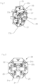
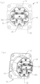
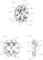
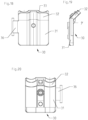
- the Figures 1 to 14 show different views, some only of components, of a first embodiment of a junction box 10 for a data or communication network.
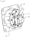
- the Figures 15 to 27 show different views, some only of components, of a second embodiment of a junction box 10 for a data or communication network. Unless otherwise stated, the following description relates to both exemplary embodiments.
- the same reference numbers denote the same or functionally the same parts. For a better overview, not all reference numbers are given in all figures.
- the junction box 10 has a housing 15, which includes a lower housing part 20 with a bottom surface 20a and an upper housing part 30 (see, for example, Figures 3 and 4 or figure 22 ).
- a printed circuit board is arranged in the housing 15, on which at least one socket 42, in the present exemplary embodiment two sockets 42, is arranged for receiving a plug in each case.
- the socket 42 is accessible in particular through an opening 41 in the housing upper part 40 (cf. figure 14 or figure 26 ).
- the individual cores of at least one cable 50 in the present case two cables 50, can be electrically conductively connected to the individual contacts of the socket 42 via connection contacts in a manner known per se.
- the cable or cables 50 are routed through an opening 29 in the lower housing part 20, in particular in the bottom surface 20a of the lower housing part 20, into the interior of the housing 15.
- a clamping device 30 for the at least one cable 50 is provided on the lower housing part 20 .
- the clamping device 30 functions in particular as strain relief for the at least one cable 50.
- the cable 50 is clamped between the clamping device 30 and the lower housing part 20.
- the lower housing part 20 has a first bearing surface 21 for the at least one cable 50 and a second bearing surface 22 for the at least one cable 50 .
- the at least one cable 50 can be fixed in a clamping manner either on the first bearing surface 21 or on the second bearing surface 22 by the clamping device 30, the first bearing surface 21 and the second bearing surface 22 are arranged at an angle ⁇ that is not equal to 0° to one another (cf. figure 17 ).
- the angle ⁇ can in particular be between 110° and 150°, preferably between 130° and 140°, particularly preferably about 135°, measured between the two bearing surfaces 21, 22.
- the first bearing surface 21 can be arranged parallel to the bottom surface 20a of the lower housing part 20 (see in particular figure 1 or figure 15 ).
- the first bearing surface 21 can have a contact contour 23a, for example in the form of a channel for the at least one cable 50 or also in the form of two channels, in particular running approximately parallel, for the two cables 50 .
- the contact contour 23a can facilitate the positioning of the cable or cables 50 on the first bearing surface 21 .
- the contact contour 23a can define the direction in which the cable or cables 50 are guided away from the housing on the bottom surface 20a, ie the direction of the cable outlet.
- the first bearing surface 21 can have a contact structure 24a, for example in the form of knobs, teeth or ribs running transversely to the longitudinal direction of the cable 50, which can improve the fixing of the cable 50 in the clamped state.
- a contact structure 24a for example in the form of knobs, teeth or ribs running transversely to the longitudinal direction of the cable 50, which can improve the fixing of the cable 50 in the clamped state.
- the second contact surface 22 is inclined at an angle ⁇ relative to the bottom surface 20a of the lower housing part 20, the angle ⁇ being in particular between 20° and 70°, preferably between 40° and 50°, particularly preferably about 45°, with the acute Angle ⁇ between the second bearing surface 22 and the bottom surface 20a is considered to be the inclination of the second bearing surface 22 against the bottom surface 20a (see FIG figure 17 ).
- the contact surface 22 can be formed, for example, on a correspondingly shaped projection 25 which is arranged on the bottom surface 20a.
- the second bearing surface 22, like the first bearing surface 21, can have a contact contour 23b, for example in the form of a channel for the at least one cable 50 or also in the form of two channels, in particular running approximately parallel, for the two cables 50.
- the contact contour 23b can facilitate the positioning of the cable or cables 50 on the first bearing surface 21 .
- the contact contour 23b can define the direction in which the cable or cables 50 are guided away from the housing on the bottom surface 20a, ie the direction of the cable outlet.
- the first bearing surface 21 can have a bearing structure 24b, for example in the form of knobs, teeth or ribs running transversely to the longitudinal direction of the cable 50, which can improve the fixing of the cable 50 in the clamped state.
- a bearing structure 24b for example in the form of knobs, teeth or ribs running transversely to the longitudinal direction of the cable 50, which can improve the fixing of the cable 50 in the clamped state.
- the clamping device 30 can have at least one plate-shaped section which is arranged approximately parallel to the corresponding bearing surface 21, 22 in order to at least to fix a cable 50 between the clamping device 30 and the corresponding support surface 21, 22 by clamping.
- the clamping device 30 can also have a contact contour 33, for example in the form of a channel for the at least one cable 50 or also in the form of two channels, in particular running approximately parallel, for the two cables 50.
- the contact contour 33 can facilitate the positioning of the cable or cables 50 .
- the contact contour 33 can define the direction in which the cable or cables 50 are guided away from the housing on the bottom surface 20a, ie the direction of the cable outlet.
- Contact contour 33 is preferably configured in such a way that when cable 50 is in contact with first contact surface 21, the groove of clamping device 30 and the groove in first contact surface 21 almost completely enclose cable 50 to be fixed, and correspondingly when cable 50 is in contact with the second contact surface 22 the groove of the clamping device 30 and the groove of the second support surface 22 also almost completely enclose the cable 50 to be fixed (see, for example, figure 4 and figure 10 or figure 22 and figure 25 ).
- the clamping device 30 can also have a contact structure (not shown), for example in the form of knobs, teeth or ribs running transversely to the longitudinal direction of the cable 50, which can improve the fixing of the cable 50 in the clamped state.
- a contact structure for example in the form of knobs, teeth or ribs running transversely to the longitudinal direction of the cable 50, which can improve the fixing of the cable 50 in the clamped state.
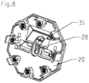
- the clamping device 30 can be fixed to the lower housing part 20 by means of a screw 35 (see FIG figures 7 and 8th or figure 21 ).
- the clamping device 30 has a first section 31, with which the at least one cable 50 can be fixed to the first bearing surface 21, and a second section 32, with which the at least one cable 50 can be fixed to the second bearing surface 22 can be fixed, with the first section 31 and the second section 32 being arranged at an angle y to one another, which corresponds in particular to the angle ⁇ between the first bearing surface 21 and the second bearing surface 22 (see Figures 19 and figures 24 and 25 ).
- the clamping device 30 can thus fix the cable 50 in a clamping manner both on the first bearing surface 21 and on the second bearing surface 22 without the alignment of the clamping device 30 relative to the lower housing part 20 having to be changed, apart from the distance from the bottom surface 20a of the lower housing part 20 (cf. figures 24 and figures 25 ).
- a projection 36 can be arranged on the clamping device 30, which can be inserted in a recess 26, which is arranged in particular on the bottom surface 20a of the lower housing part 20, in particular in a form-fitting manner (cf . for example figure 23 ). In this way it can be ensured that the clamping device 30 is always arranged in the same orientation relative to the lower housing part 20 even after it has been removed and replaced.
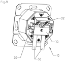
- the clamping device 30 is between a first position (see Figures 5, 6 and 9 ), in which the at least one cable 50 can be fixed to the first bearing surface 21, and a second position (see Figures 3, 4 and 10 ), in which the at least one cable 50 can be fixed to the second bearing surface, is movable.
- the movement can, for example, Be pivotal movement when the clamping device 30 is designed in the manner of a flap and pivotable about a pivot axis between the two positions.
- the movement is a translation movement, i.e. the clamping device 30 may be fixed to a location on the junction box 10 in which it can be placed in the first position, and alternatively the clamping device may be fixed to a different location on the junction box 10 be fixed, in which it can be brought into the second position.
- the clamping device 30 can be designed as a substantially rectangular plate-like element.
- the clamping device 30 can have at least one projection 36 which, in the first position, is in a first recess 26a (see in particular figure 5 ) and in the second position in a second recess (see in particular figure 3 ) 26b is arranged.
- the clamping device 30 can have two projections 36 .
- the projections 36 can be pin-like and in particular can be arranged in alignment on opposite side edges of the clamping device 30 (cf. in particular Figures 12 and 13 ), whereby they can also form a pivot axis.
- the clamping device 30 can be pivoted about the projections 36 both in the first recess 26a and in the second recess 26b.
- the recess 26a, 26b can be designed with an undercut 27 and the projection 36 can have such a non-round cross-section (cf. figure 11 ) that the projection 36 only in one orientation relative to the recess 26a, 26b in the recess 26a, 26b can be used.
- the non-circular cross-section of the projection 36 can be formed, for example, by providing a flattened area 36a, preferably also two parallel flattened areas 36a, on the otherwise circular-cylindrical projection 36 (cf. figure 11 ).
- the cables 50 are placed on the first contact surface 21 or on the second contact surface 22, then the clamping device 30 with the projections 36 is inserted into the first recess 26a for the first contact surface 21 or the second recess 26b for the second Contact surface 22 is pushed in, with, for example, the clamping device 30 being aligned with its plate-like element approximately perpendicularly to the bottom surface 20a of the lower housing part 20, and finally the clamping device 30 is moved around the projections 36 into the appropriate position for clamping the cable 50 to the corresponding contact surface 21, 22 pivoted.
- the clamping device 30 can be fixed in this position by means of the screw 35 .
- the present exemplary embodiments result in a cable outlet of approximately 90° relative to a central housing axis A, which is arranged running perpendicular to the bottom surface 20a. If the at least one cable 50 is in contact with the second contact surface 22, the present exemplary embodiments result in a cable outlet of approximately 45° relative to the central axis A of the housing.
- the screw 35 can be arranged in a groove 28 so that it can be displaced.
- figure 7 shows to the position of the screw for fixing the clamping device 30 in the first position
- figure 8 represents the position of the screw 35 for fixing the clamping device 30 in the second position.
- the upper housing part 40 can be placed on the lower housing part 20 and can be fixed on the lower housing part 20 in a plurality of positions rotated relative to one another about the central axis A of the housing.
- the upper housing part 40 and the lower housing part 20 have, for example, an outer contour in the form of a regular N-corner, if N designates the number of different positions.
- the cable outlet can point in N different directions.
- the upper housing part 40 can be fixed to the lower housing part 20 in at least four, preferably at least six, in the present exemplary embodiments in eight, positions rotated relative to one another about the central axis A of the housing. In combination with the two different inclinations for the cable outlet, there are a total of sixteen different directions for the cable outlet of the at least one cable 50 with eight different positions.
Landscapes
- Insertion, Bundling And Securing Of Wires For Electric Apparatuses (AREA)
Applications Claiming Priority (1)
| Application Number | Priority Date | Filing Date | Title |
|---|---|---|---|
| DE102021125801.4A DE102021125801A1 (de) | 2021-10-05 | 2021-10-05 | Anschlussdose für ein Daten- oder Kommunikationsnetz |
Publications (2)
| Publication Number | Publication Date |
|---|---|
| EP4164067A1 true EP4164067A1 (fr) | 2023-04-12 |
| EP4164067B1 EP4164067B1 (fr) | 2025-06-25 |
Family
ID=82899384
Family Applications (1)
| Application Number | Title | Priority Date | Filing Date |
|---|---|---|---|
| EP22189696.2A Active EP4164067B1 (fr) | 2021-10-05 | 2022-08-10 | Prise de connexion pour un réseau de données ou de communication |
Country Status (2)
| Country | Link |
|---|---|
| EP (1) | EP4164067B1 (fr) |
| DE (1) | DE102021125801A1 (fr) |
Families Citing this family (1)
| Publication number | Priority date | Publication date | Assignee | Title |
|---|---|---|---|---|
| DE102022133969B4 (de) * | 2022-12-19 | 2025-07-03 | Metz Connect Tech Gmbh | Anschlussdose für mindestens ein Datenkabel |
Citations (5)
| Publication number | Priority date | Publication date | Assignee | Title |
|---|---|---|---|---|
| EP0908972A1 (fr) * | 1997-10-07 | 1999-04-14 | Legrand | Serre-câble et appareil électrique équipé d'un tel serre-câble |
| DE19926347A1 (de) * | 1999-06-09 | 2001-04-19 | Krone Gmbh | Einrichtung zur Zugentlastung für Kabel |
| DE19953187A1 (de) * | 1999-11-05 | 2001-06-13 | Rutenbeck Wilhelm Gmbh & Co | Elektrisches Installationsteil für den Anschluss von Datenleitungen |
| DE10163861A1 (de) * | 2001-12-22 | 2003-07-17 | Gaertner Karl Telegaertner | Anschlussdose |
| DE102004025188A1 (de) | 2004-05-22 | 2005-12-15 | Ria-Btr Produktions-Gmbh | Anschlussdose |
Family Cites Families (1)
| Publication number | Priority date | Publication date | Assignee | Title |
|---|---|---|---|---|
| DE102011113088A1 (de) | 2011-09-09 | 2013-03-14 | Kathrein-Werke Kg | Multimedia-Dose |
-
2021
- 2021-10-05 DE DE102021125801.4A patent/DE102021125801A1/de active Pending
-
2022
- 2022-08-10 EP EP22189696.2A patent/EP4164067B1/fr active Active
Patent Citations (5)
| Publication number | Priority date | Publication date | Assignee | Title |
|---|---|---|---|---|
| EP0908972A1 (fr) * | 1997-10-07 | 1999-04-14 | Legrand | Serre-câble et appareil électrique équipé d'un tel serre-câble |
| DE19926347A1 (de) * | 1999-06-09 | 2001-04-19 | Krone Gmbh | Einrichtung zur Zugentlastung für Kabel |
| DE19953187A1 (de) * | 1999-11-05 | 2001-06-13 | Rutenbeck Wilhelm Gmbh & Co | Elektrisches Installationsteil für den Anschluss von Datenleitungen |
| DE10163861A1 (de) * | 2001-12-22 | 2003-07-17 | Gaertner Karl Telegaertner | Anschlussdose |
| DE102004025188A1 (de) | 2004-05-22 | 2005-12-15 | Ria-Btr Produktions-Gmbh | Anschlussdose |
Also Published As
| Publication number | Publication date |
|---|---|
| DE102021125801A1 (de) | 2023-04-06 |
| EP4164067B1 (fr) | 2025-06-25 |
Similar Documents
| Publication | Publication Date | Title |
|---|---|---|
| EP1096605B1 (fr) | Dispositif de connexion ou de jonction de cables | |
| EP3701595B1 (fr) | Cadre de retenue pour un connecteur industriel | |
| EP0260425A1 (fr) | Dispositif de soulagement de la traction | |
| EP0954887A1 (fr) | Dispositif de connexion pour au moins un conducteur non denude | |
| EP1131860A1 (fr) | Dispositif de mise en contact pour cable plat | |
| DE2511385C3 (de) | Elektrische Anschlußklemme | |
| EP3981046B1 (fr) | Connecteur de carte de circuit imprimé modulaire | |
| EP4164067B1 (fr) | Prise de connexion pour un réseau de données ou de communication | |
| EP0156019A2 (fr) | Dispositif pour l'assemblage d'éléments de cloisons pour socles de chariots dans des installations d'impression | |
| EP2583357B1 (fr) | Bloc de jonction | |
| EP0695008A1 (fr) | Dispositif de blocage de câble universel | |
| DE3618108C2 (fr) | ||
| EP4591404A1 (fr) | Élément de contact électrique, insert de connecteur enfichable et connecteur enfichable industriel modulaire le comprenant | |
| DE10029222A1 (de) | Elektrisches Installationsgerät | |
| EP0901186A2 (fr) | Borne de connexion pour des câbles blindés | |
| AT397332B (de) | Zugentlastung | |
| DE10205614B4 (de) | Anschlussadapter | |
| EP3855572A1 (fr) | Borne de liaison | |
| DE102017102223B3 (de) | Steckverbinder mit Schutzleiterbrücke | |
| EP4391235B1 (fr) | Boîte de jonction pour au moins un câble de données | |
| DE4026124A1 (de) | Anschlussdose fuer elektrische leitungen | |
| EP3490070A1 (fr) | Élément de raccordement de câble | |
| DE4217906A1 (de) | Kabeleinführungstülle sowie Verbindungs- und Verteilerdose, insbesondere für Fenrmeldekabel, mit wenigstens einer Kabeleinführungstülle | |
| DE10231850B4 (de) | Klemmvorrichtung zur Montage eines geschirmten Kabels | |
| DE29619939U1 (de) | Elektroinstallations-Vorrichtung zum Anschließen von elektrischen Drähten |
Legal Events
| Date | Code | Title | Description |
|---|---|---|---|
| PUAI | Public reference made under article 153(3) epc to a published international application that has entered the european phase |
Free format text: ORIGINAL CODE: 0009012 |
|
| STAA | Information on the status of an ep patent application or granted ep patent |
Free format text: STATUS: THE APPLICATION HAS BEEN PUBLISHED |
|
| AK | Designated contracting states |
Kind code of ref document: A1 Designated state(s): AL AT BE BG CH CY CZ DE DK EE ES FI FR GB GR HR HU IE IS IT LI LT LU LV MC MK MT NL NO PL PT RO RS SE SI SK SM TR |
|
| P01 | Opt-out of the competence of the unified patent court (upc) registered |
Effective date: 20230417 |
|
| STAA | Information on the status of an ep patent application or granted ep patent |
Free format text: STATUS: REQUEST FOR EXAMINATION WAS MADE |
|
| 17P | Request for examination filed |
Effective date: 20230914 |
|
| RBV | Designated contracting states (corrected) |
Designated state(s): AL AT BE BG CH CY CZ DE DK EE ES FI FR GB GR HR HU IE IS IT LI LT LU LV MC MK MT NL NO PL PT RO RS SE SI SK SM TR |
|
| GRAP | Despatch of communication of intention to grant a patent |
Free format text: ORIGINAL CODE: EPIDOSNIGR1 |
|
| STAA | Information on the status of an ep patent application or granted ep patent |
Free format text: STATUS: GRANT OF PATENT IS INTENDED |
|
| RIC1 | Information provided on ipc code assigned before grant |
Ipc: H01R 25/00 20060101ALN20250224BHEP Ipc: H01R 24/64 20110101ALN20250224BHEP Ipc: H01R 13/58 20060101AFI20250224BHEP |
|
| INTG | Intention to grant announced |
Effective date: 20250310 |
|
| GRAS | Grant fee paid |
Free format text: ORIGINAL CODE: EPIDOSNIGR3 |
|
| GRAA | (expected) grant |
Free format text: ORIGINAL CODE: 0009210 |
|
| STAA | Information on the status of an ep patent application or granted ep patent |
Free format text: STATUS: THE PATENT HAS BEEN GRANTED |
|
| AK | Designated contracting states |
Kind code of ref document: B1 Designated state(s): AL AT BE BG CH CY CZ DE DK EE ES FI FR GB GR HR HU IE IS IT LI LT LU LV MC MK MT NL NO PL PT RO RS SE SI SK SM TR |
|
| REG | Reference to a national code |
Ref country code: GB Ref legal event code: FG4D Free format text: NOT ENGLISH |
|
| REG | Reference to a national code |
Ref country code: CH Ref legal event code: EP |
|
| REG | Reference to a national code |
Ref country code: DE Ref legal event code: R096 Ref document number: 502022004387 Country of ref document: DE |
|
| REG | Reference to a national code |
Ref country code: CH Ref legal event code: EP |
|
| REG | Reference to a national code |
Ref country code: IE Ref legal event code: FG4D Free format text: LANGUAGE OF EP DOCUMENT: GERMAN |
|
| RAP2 | Party data changed (patent owner data changed or rights of a patent transferred) |
Owner name: METZ CONNECT GMBH |
|
| REG | Reference to a national code |
Ref country code: DE Ref legal event code: R081 Ref document number: 502022004387 Country of ref document: DE Owner name: METZ CONNECT GMBH, DE Free format text: FORMER OWNER: METZ CONNECT TECH GMBH, 78176 BLUMBERG, DE |
|
| RAP4 | Party data changed (patent owner data changed or rights of a patent transferred) |
Owner name: METZ CONNECT GMBH |
|
| PG25 | Lapsed in a contracting state [announced via postgrant information from national office to epo] |
Ref country code: FI Free format text: LAPSE BECAUSE OF FAILURE TO SUBMIT A TRANSLATION OF THE DESCRIPTION OR TO PAY THE FEE WITHIN THE PRESCRIBED TIME-LIMIT Effective date: 20250625 |
|
| REG | Reference to a national code |
Ref country code: LT Ref legal event code: MG9D |
|
| PG25 | Lapsed in a contracting state [announced via postgrant information from national office to epo] |
Ref country code: GR Free format text: LAPSE BECAUSE OF FAILURE TO SUBMIT A TRANSLATION OF THE DESCRIPTION OR TO PAY THE FEE WITHIN THE PRESCRIBED TIME-LIMIT Effective date: 20250926 Ref country code: NO Free format text: LAPSE BECAUSE OF FAILURE TO SUBMIT A TRANSLATION OF THE DESCRIPTION OR TO PAY THE FEE WITHIN THE PRESCRIBED TIME-LIMIT Effective date: 20250925 |
|
| PGFP | Annual fee paid to national office [announced via postgrant information from national office to epo] |
Ref country code: IT Payment date: 20250901 Year of fee payment: 4 |
|
| PG25 | Lapsed in a contracting state [announced via postgrant information from national office to epo] |
Ref country code: BG Free format text: LAPSE BECAUSE OF FAILURE TO SUBMIT A TRANSLATION OF THE DESCRIPTION OR TO PAY THE FEE WITHIN THE PRESCRIBED TIME-LIMIT Effective date: 20250625 |
|
| PG25 | Lapsed in a contracting state [announced via postgrant information from national office to epo] |
Ref country code: HR Free format text: LAPSE BECAUSE OF FAILURE TO SUBMIT A TRANSLATION OF THE DESCRIPTION OR TO PAY THE FEE WITHIN THE PRESCRIBED TIME-LIMIT Effective date: 20250625 |
|
| PGFP | Annual fee paid to national office [announced via postgrant information from national office to epo] |
Ref country code: AT Payment date: 20251020 Year of fee payment: 4 |
|
| PG25 | Lapsed in a contracting state [announced via postgrant information from national office to epo] |
Ref country code: RS Free format text: LAPSE BECAUSE OF FAILURE TO SUBMIT A TRANSLATION OF THE DESCRIPTION OR TO PAY THE FEE WITHIN THE PRESCRIBED TIME-LIMIT Effective date: 20250925 |
|
| REG | Reference to a national code |
Ref country code: CH Ref legal event code: U11 Free format text: ST27 STATUS EVENT CODE: U-0-0-U10-U11 (AS PROVIDED BY THE NATIONAL OFFICE) Effective date: 20251027 |
|
| PG25 | Lapsed in a contracting state [announced via postgrant information from national office to epo] |
Ref country code: LV Free format text: LAPSE BECAUSE OF FAILURE TO SUBMIT A TRANSLATION OF THE DESCRIPTION OR TO PAY THE FEE WITHIN THE PRESCRIBED TIME-LIMIT Effective date: 20250625 |
|
| REG | Reference to a national code |
Ref country code: NL Ref legal event code: MP Effective date: 20250625 |
|
| PG25 | Lapsed in a contracting state [announced via postgrant information from national office to epo] |
Ref country code: NL Free format text: LAPSE BECAUSE OF FAILURE TO SUBMIT A TRANSLATION OF THE DESCRIPTION OR TO PAY THE FEE WITHIN THE PRESCRIBED TIME-LIMIT Effective date: 20250625 |
|
| PG25 | Lapsed in a contracting state [announced via postgrant information from national office to epo] |
Ref country code: PT Free format text: LAPSE BECAUSE OF FAILURE TO SUBMIT A TRANSLATION OF THE DESCRIPTION OR TO PAY THE FEE WITHIN THE PRESCRIBED TIME-LIMIT Effective date: 20251027 |
|
| PG25 | Lapsed in a contracting state [announced via postgrant information from national office to epo] |
Ref country code: IS Free format text: LAPSE BECAUSE OF FAILURE TO SUBMIT A TRANSLATION OF THE DESCRIPTION OR TO PAY THE FEE WITHIN THE PRESCRIBED TIME-LIMIT Effective date: 20251025 |
|
| PG25 | Lapsed in a contracting state [announced via postgrant information from national office to epo] |
Ref country code: SM Free format text: LAPSE BECAUSE OF FAILURE TO SUBMIT A TRANSLATION OF THE DESCRIPTION OR TO PAY THE FEE WITHIN THE PRESCRIBED TIME-LIMIT Effective date: 20250625 |
|
| PGFP | Annual fee paid to national office [announced via postgrant information from national office to epo] |
Ref country code: FR Payment date: 20251017 Year of fee payment: 4 |
|
| PGFP | Annual fee paid to national office [announced via postgrant information from national office to epo] |
Ref country code: CH Payment date: 20251027 Year of fee payment: 4 |
|
| PG25 | Lapsed in a contracting state [announced via postgrant information from national office to epo] |
Ref country code: CZ Free format text: LAPSE BECAUSE OF FAILURE TO SUBMIT A TRANSLATION OF THE DESCRIPTION OR TO PAY THE FEE WITHIN THE PRESCRIBED TIME-LIMIT Effective date: 20250625 |
|
| PG25 | Lapsed in a contracting state [announced via postgrant information from national office to epo] |
Ref country code: PL Free format text: LAPSE BECAUSE OF FAILURE TO SUBMIT A TRANSLATION OF THE DESCRIPTION OR TO PAY THE FEE WITHIN THE PRESCRIBED TIME-LIMIT Effective date: 20250625 |
|
| PG25 | Lapsed in a contracting state [announced via postgrant information from national office to epo] |
Ref country code: EE Free format text: LAPSE BECAUSE OF FAILURE TO SUBMIT A TRANSLATION OF THE DESCRIPTION OR TO PAY THE FEE WITHIN THE PRESCRIBED TIME-LIMIT Effective date: 20250625 |
|
| PG25 | Lapsed in a contracting state [announced via postgrant information from national office to epo] |
Ref country code: SK Free format text: LAPSE BECAUSE OF FAILURE TO SUBMIT A TRANSLATION OF THE DESCRIPTION OR TO PAY THE FEE WITHIN THE PRESCRIBED TIME-LIMIT Effective date: 20250625 |
|
| PG25 | Lapsed in a contracting state [announced via postgrant information from national office to epo] |
Ref country code: ES Free format text: LAPSE BECAUSE OF FAILURE TO SUBMIT A TRANSLATION OF THE DESCRIPTION OR TO PAY THE FEE WITHIN THE PRESCRIBED TIME-LIMIT Effective date: 20250625 |
|
| REG | Reference to a national code |
Ref country code: AT Ref legal event code: PC Ref document number: 1807588 Country of ref document: AT Kind code of ref document: T Owner name: METZ CONNECT GMBH, DE Effective date: 20251216 |
|
| PG25 | Lapsed in a contracting state [announced via postgrant information from national office to epo] |
Ref country code: RO Free format text: LAPSE BECAUSE OF FAILURE TO SUBMIT A TRANSLATION OF THE DESCRIPTION OR TO PAY THE FEE WITHIN THE PRESCRIBED TIME-LIMIT Effective date: 20250625 |
|
| REG | Reference to a national code |
Ref country code: DE Ref legal event code: R097 Ref document number: 502022004387 Country of ref document: DE |
|
| PG25 | Lapsed in a contracting state [announced via postgrant information from national office to epo] |
Ref country code: MC Free format text: LAPSE BECAUSE OF FAILURE TO SUBMIT A TRANSLATION OF THE DESCRIPTION OR TO PAY THE FEE WITHIN THE PRESCRIBED TIME-LIMIT Effective date: 20250625 |
|
| PG25 | Lapsed in a contracting state [announced via postgrant information from national office to epo] |
Ref country code: DK Free format text: LAPSE BECAUSE OF FAILURE TO SUBMIT A TRANSLATION OF THE DESCRIPTION OR TO PAY THE FEE WITHIN THE PRESCRIBED TIME-LIMIT Effective date: 20250625 |
|
| PGFP | Annual fee paid to national office [announced via postgrant information from national office to epo] |
Ref country code: DE Payment date: 20260128 Year of fee payment: 4 |
|
| PG25 | Lapsed in a contracting state [announced via postgrant information from national office to epo] |
Ref country code: LU Free format text: LAPSE BECAUSE OF NON-PAYMENT OF DUE FEES Effective date: 20250810 |
|
| PLBE | No opposition filed within time limit |
Free format text: ORIGINAL CODE: 0009261 |
|
| STAA | Information on the status of an ep patent application or granted ep patent |
Free format text: STATUS: NO OPPOSITION FILED WITHIN TIME LIMIT |
|
| REG | Reference to a national code |
Ref country code: CH Ref legal event code: L10 Free format text: ST27 STATUS EVENT CODE: U-0-0-L10-L00 (AS PROVIDED BY THE NATIONAL OFFICE) Effective date: 20260507 |