EP4164125A1 - Commande de gain automatique dans un réseau de communication sans fil pour la commande de réseau électrique - Google Patents
Commande de gain automatique dans un réseau de communication sans fil pour la commande de réseau électrique Download PDFInfo
- Publication number
- EP4164125A1 EP4164125A1 EP22212037.0A EP22212037A EP4164125A1 EP 4164125 A1 EP4164125 A1 EP 4164125A1 EP 22212037 A EP22212037 A EP 22212037A EP 4164125 A1 EP4164125 A1 EP 4164125A1
- Authority
- EP
- European Patent Office
- Prior art keywords
- packet
- automatic gain
- lpf
- sequence
- gain control
- Prior art date
- Legal status (The legal status is an assumption and is not a legal conclusion. Google has not performed a legal analysis and makes no representation as to the accuracy of the status listed.)
- Pending
Links
Images



Classifications
-
- H—ELECTRICITY
- H03—ELECTRONIC CIRCUITRY
- H03G—CONTROL OF AMPLIFICATION
- H03G3/00—Gain control in amplifiers or frequency changers
- H03G3/20—Automatic control
- H03G3/30—Automatic control in amplifiers having semiconductor devices
- H03G3/3036—Automatic control in amplifiers having semiconductor devices in high-frequency amplifiers or in frequency-changers
-
- H—ELECTRICITY
- H03—ELECTRONIC CIRCUITRY
- H03G—CONTROL OF AMPLIFICATION
- H03G3/00—Gain control in amplifiers or frequency changers
- H03G3/20—Automatic control
- H03G3/30—Automatic control in amplifiers having semiconductor devices
- H03G3/3052—Automatic control in amplifiers having semiconductor devices in bandpass amplifiers (H.F. or I.F.) or in frequency-changers used in a (super)heterodyne receiver
- H03G3/3078—Circuits generating control signals for digitally modulated signals
-
- H—ELECTRICITY
- H04—ELECTRIC COMMUNICATION TECHNIQUE
- H04L—TRANSMISSION OF DIGITAL INFORMATION, e.g. TELEGRAPHIC COMMUNICATION
- H04L27/00—Modulated-carrier systems
- H04L27/26—Systems using multi-frequency codes
- H04L27/2601—Multicarrier modulation systems
-
- H—ELECTRICITY
- H03—ELECTRONIC CIRCUITRY
- H03G—CONTROL OF AMPLIFICATION
- H03G2201/00—Indexing scheme relating to subclass H03G
- H03G2201/10—Gain control characterised by the type of controlled element
- H03G2201/103—Gain control characterised by the type of controlled element being an amplifying element
Definitions
- Embodiments presented herein relate to a method, a packet receiver, a computer program, and a computer program product for automatic gain control in a wireless communication network for power grid control.
- Currently available industrial wireless standards such as WirelessHART (where HART is short for Highway Addressable Remote Transducer) or Wireless Network for Industrial Automation - Factory Automation (WIA-FA), are not able to provide very high performance in these regards, because they rely on non-optimized physical (PHY) communications layers.
- WIA-FA is based on the IEEE 802.11g/n PHY layer, whose minimum transmission time for a packet of 100 bits is around 30 ⁇ s, while many power grid applications, currently based on wired local area networks (LANs) compliant with IEC 61850, require a slot time of a few ⁇ s or even lower.
- LANs local area networks
- AGC automatic gain control
- VGA variable gain amplifier
- the gain setting of the VGA is initialized to a nominal value and it reaches the optimal value after a certain amount of time, called settling time. During this time, the AGC processes the first samples of the received preamble, which are discarded afterwards. This procedure is repeated for each packet, since the signals received by different transmitters have considerably different amplitudes.
- the optimal setting of the VGA gain is performed by using long preambles (e.g. as disclosed in US 20040242177 A1 ) or out-of-slot dedicated packets (e.g. as disclosed in US 20030091132 A1 and US 5524009 A ).
- An object of embodiments herein is to provide efficient automatic gain control that does not suffer from the issues identified above, or at least where the issues noted above are reduced or mitigated.
- a method for automatic gain control in a wireless communication network for power grid control employs time based scheduling of packets.
- the method is performed by a packet receiver in the wireless communication network.
- the method comprises receiving a packet from a packet transmitter.
- the packet comprises a preamble.
- the preamble is composed of a single OFDM symbol.
- the preamble is represented by a sequence of samples.
- the method comprises applying automatic gain control to the sequence of samples after variable gain amplitude control has been applied to the sequence of samples.
- the automatic gain control involves applying an LPF to the sequence of automatic gain controlled samples.
- the LPF is selected from a bank of LPSs. Which LPF to apply depends on, according to the time based scheduling, from which packet transmitter the packet is received.
- a packet receiver for automatic gain control in a wireless communication network for power grid control employs time based scheduling of packets.
- the packet receiver comprises processing circuitry.
- the processing circuitry is configured to cause the packet receiver to receive a packet from a packet transmitter.
- the packet comprises a preamble.
- the preamble is composed of a single OFDM symbol.
- the preamble is represented by a sequence of samples.
- the processing circuitry is configured to cause the packet receiver to apply automatic gain control to the sequence of samples after variable gain amplitude control has been applied to the sequence of samples.
- the automatic gain control involves applying an LPF to the sequence of automatic gain controlled samples.
- the LPF is selected from a bank of LPSs. Which LPF to apply depends on, according to the time based scheduling, from which packet transmitter the packet is received.
- a computer program for automatic gain control in a wireless communication network for power grid control comprising computer program code which, when run on a packet receiver, causes the packet receiver to perform a method according to the first aspect.
- a computer program product comprising a computer program according to the third aspect and a computer readable storage medium on which the computer program is stored.
- the computer readable storage medium could be a non-transitory computer readable storage medium.
- the proposed automatic gain control does not suffer from the issues noted above.
- the proposed method allows an efficient packet structure, enabling low latency wireless communications.
- the use of the short preamble enables low latency to be achieved by avoiding the latency caused by the settling time as necessary in traditional AGC systems.
- any feature of the first, second, third, and fourth aspects may be applied to any other aspect, wherever appropriate.
- any advantage of the first aspect may equally apply to the second, third, and/or fourth aspect, respectively, and vice versa.
- Other objectives, features and advantages of the enclosed embodiments will be apparent from the following detailed disclosure, from the attached dependent claims as well as from the drawings.
- Fig. 1 schematically illustrates a wireless communication network 100 wherein the herein disclosed embodiments apply.
- Network entities denoted nodes 200a, 200b, ...., 200N are equipped with a radio frequency (RF) front-end that allows them to communicate over a wireless network 110.
- Each node may represent a component of a substation automation system, such as a gateway, circuit breaker, circuit protector, transformer, switchgear, etc., that is configured for exchanging control messages.
- Each node 200a-200N may selectively act as a packet transmitter or a packet receiver. Without loss of generality it will hereinafter be assumed that node 200a will act as a packet receiver and that any of nodes 200b-200N will act as a packet transmitter.
- Fig. 2 schematically illustrates typical application of automatic gain control in a packet receiver 200a.
- the packet receiver 200a employs a feed-back AGC architecture.
- the amplitude of the signal, V OUT at the output of the VGA 410 is first measured with a power detector 420. Then, this value is processed by an AGC 430, which compares it with a target level and feeds the difference to a low-pass filter (LPF).
- the LPF drives the gain setting of the VGA 410 so that V OUT converges to the target value after a certain settling time.
- the power detector 420 and AGC 430 can be implemented with digital or analog components, depending on the required performance and complexity. Moreover, a feed-forward architecture can be considered, where the input signal, V IN , to the VGA 410 is measured and fed to the AGC 430.
- each packet comprises an initial sequence of samples that are processed by the system for automatic gain control until convergence is reached after the settling time.
- Fig. 3 schematically illustrates the packet structure of a packet 300 as used in IEEE 802.ng.
- the packet 300 comprises a (PHY layer) preamble 310 and a data part 320.
- the preamble 310 comprises a legacy short training field (L-STF) part and a legacy long training field (L-LTF) part.
- L-STF legacy short training field
- L-LTF legacy long training field
- the first short training sequences of the L-STF part of the preamble 310 are used for AGC.
- the size of the PHY layer preamble should be kept small, possibly limited to just one single orthogonal frequency-division multiplexing (OFDM) symbol.
- OFDM orthogonal frequency-division multiplexing
- the embodiments disclosed herein thus relate to mechanisms for automatic gain control in a wireless communication network 100 for power grid control.
- a packet receiver 200a a method performed by the packet receiver 200a, a computer program product comprising code, for example in the form of a computer program, that when run on a packet receiver 200a, causes the packet receiver 200a to perform the method.
- the packet structure is optimized and a short preamble is used. Further, in order to ensure reliable communications, knowledge of the packet scheduling is used by the automatic gain control mechanism that allows simple and reliable automatic gain control, even when a short preamble is adopted.
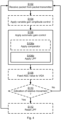
- Fig. 4 is a flowchart illustrating embodiments of methods for automatic gain control in a wireless communication network 100 for power grid control.
- the wireless communication network 100 employs time based scheduling of packets.
- the methods are performed by the packet receiver 200a.
- the methods are advantageously provided as computer programs 820.
- the packet receiver 200a receives a packet 300 from one of the other nodes acting as packet transmitter 200b-200N.
- the packet receiver 200a is thus configured to perform step S102: S102: The packet receiver 200a receives a packet 300 from a packet transmitter 200b-200N.
- the packet 300 comprises a preamble 310.
- the preamble 310 is composed of a single OFDM symbol.
- the preamble 310 is represented by a sequence of samples.
- the packet receiver 200a is thus configured to perform step S106: S106: The packet receiver 200a applies automatic gain control to the sequence of samples after variable gain amplitude control has been applied to the sequence of samples.
- the time based scheduling of packets enables the automatic gain control to rapidly switch between different gain values as soon as a new transmission begins, i.e. as soon as a new packet is received by the packet receiver 200a.
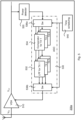
- FIG. 5 schematically illustrates application of automatic gain control in a packet receiver 200a according to embodiments.
- the packet receiver 200a in Fig. 2 comprises a VGA 510, a power detector 520, and an AGC 530.
- the packet receiver 200a in Fig. 5 differs from the packet receiver 200a of Fig. 2 in the way the AGC 530 is configured.
- the automatic gain control involves applying (step Sio6b) an LPF 532 to the sequence of automatic gain controlled samples.
- the LPF 532 is selected from a bank of LPSs 532. Which LPF 532 to apply depends on, according to the time based scheduling, from which packet transmitter 200b, 200c, ..., 200N the packet 300 is received.
- Embodiments relating to further details of automatic gain control in a wireless communication network 100 for power grid control as performed by the packet receiver 200a will now be disclosed.
- the time based scheduling is based on strict timing synchronization (e.g. time-division multiple access (TDMA)) and is maintained by a central entity (e.g. a network coordinator in the wireless communication network 100) and distributed among all the nodes 200a-200N.
- TDMA time-division multiple access
- a central entity e.g. a network coordinator in the wireless communication network 100
- each node 200a-200N knows exactly when it will receive a packet and from which packet transmitter.
- Fig. 5 this is illustrated by information from a timing scheduling module 540 being input to the AGC 530.
- variable gain amplitude control is applied by a VGA 510.
- the packet receiver 200a is configured to perform (optional) step S104: S104: The packet receiver 200a applies variable gain amplitude control to the sequence of samples, resulting in a sequence of variable gain amplitude controlled samples. The automatic gain control is then applied to the sequence of variable gain amplitude controlled samples.
- step S106 applying the automatic gain control (as in step S106) produces one automatic gain control value for the packet 300.
- the automatic gain control value is fed to the VGA 510.
- the packet receiver 200a is configured to perform (optional) step S108: S108: The packet receiver 200a feeds the automatic gain control value as a control signal.
- the control signal is to be used during the variable gain amplitude control when applied to a next packet 300 from the same packet transmitter 200b, 200C, ..., 200N.
- the automatic gain control value could be fed either as feed-back input (as in the illustrative example of Fig. 5 ) or as feed-forward input.
- the accuracy of the automatic gain control increases with the number of previously determined automatic gain control values for the same packet receiver 200b, 200c, ..., 200N. Therefore, the use of the LPF 532 ensures that the automatic gain control value converges to its optimum value.
- the state of the LPF 532 might therefore not be reset after reception of each packet 300.
- the state of the filter is defined by the K latest-most automatic gain control values for the same packet transmitter 200b, 200c, ..., 200N.
- the automatic gain control value depends, via the LPF 532, on a previous automatic gain control value for the same packet transmitter 200b, 200c, ..., 200N.
- the knowledge of the time scheduling will allow the packet receiver 200a to select the appropriate LPF 532 in the bank of LPs 532 to update with the just determined automatic gain control value.
- the packet receiver 200b is configured to perform (optional) step S110: S110: The packet receiver 200a receives an indication of relative movement between the packet receiver 200a and the packet transmitter 200b, 200c, ..., 200N.
- the packet receiver 200a could be different ways for the packet receiver 200a to receive the indication of relative movement.
- the indication is received from protocol layers higher than the PHY layer.
- the indication might be provided as localization information on the application layer.
- the packet receiver 200a is then configured to, in and in response thereto (i.e., in response to having received the indication in step S112) perform step S114: S114: The packet receiver 200a resets the LPF 532 to a default state, wherein in the default state the automatic gain control value does not depend on any previous automatic gain control value.
- the state of the filter is defined by the K latest-most automatic gain control values for the same packet transmitter 200b, 200c, ..., 200N.
- Resetting the filter might thus comprise setting all the K latest-most automatic gain control values as used in the filter to default values.
- the AGC 530 comprises at least one comparator 534.
- the packet receiver 200a is configured to perform (optional) step Sio6a: S106a: The packet receiver 200a applies applying a comparator 534 to the sequence of variable gain amplitude controlled samples before applying the LPF.
- comparator 534 There could be different types of configurations for the comparator 534. Different embodiments relating thereto will now be disclosed.
- the AGC 530 comprises one single comparator 534.
- one common comparator 534 is applied irrespectively of from which packet transmitter 200b, 200c, ..., 200N the packet 300 is received. This yields a simple implementation (both in terms of storage and use) of the comparator 534.
- the AGC 530 comprises a bank of comparators 534.
- the comparator 534 is selected from a bank of comparators 534. This enables the comparators 534 in the bank of comparators 534 to be tailored for different purposes and hence enables a flexible use of different comparators 534 as needed.
- comparators 534 there is as many comparators 534 as there are potential packet transmitters 200b, 200c, ..., 200N. Particularly, according to an embodiment, which comparator 534 to apply depends on, according to the time based scheduling, from which packet transmitter 200b, 200c, ..., 200N the packet 300 is received.
- comparators 534 there is as many comparators 534 as there are types of potential packet transmitters 200b, 200c, ..., 200N. Particularly, according to an embodiment, which comparator 534 to apply depends on from which type of packet transmitter 200b, 200c, ..., 200N the packet 300 is received. That is, there could be one comparator selected if the packet transmitter is a gateway, another comparator selected if the packet transmitter is a circuit breaker, yet another comparator selected if the packet transmitter is a circuit protector, etc.
- the first switch 536a is placed between the single comparator 534 and the bank of LPFs 532.
- the switches 536a, 536b can be implemented through analog or digital components, depending on the required performance and complexity.
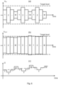
- Fig. 6 at (a), (b), and (c) schematically illustrates V IN , V OUT , and G as a function of time, where one packet at a time is received in turn from M packet transmitters according to the time based scheduling. The values of V IN , V OUT are compared to the target gain value.
- the gain values applied in consecutive packets as received from different transmitters change significantly, requiring a fast switching process for the AGC.
- the gain values are quite similar, progressively converging to the optimal value according to the LPF behavior (as given by the dash-dotted line in Fig. 6(c) ).
- Fig. 7 schematically illustrates, in terms of a number of functional units, the components of a packet receiver 200a according to an embodiment.
- Processing circuitry 210 is provided using any combination of one or more of a suitable central processing unit (CPU), multiprocessor, microcontroller, digital signal processor (DSP), etc., capable of executing software instructions stored in a computer program product 810 (as in Fig. 8 ), e.g. in the form of a storage medium 230.
- the processing circuitry 210 may further be provided as at least one application specific integrated circuit (ASIC), or field programmable gate array (FPGA).
- ASIC application specific integrated circuit
- FPGA field programmable gate array
- the processing circuitry 210 is configured to cause the packet receiver 200a to perform a set of operations, or steps, S102-S104e, as disclosed above.
- the storage medium 230 may store the set of operations
- the processing circuitry 210 may be configured to retrieve the set of operations from the storage medium 230 to cause the packet receiver 200a to perform the set of operations.
- the set of operations may be provided as a set of executable instructions.
- the processing circuitry 210 is thereby arranged to execute methods as herein disclosed.
- the storage medium 230 may also comprise persistent storage, which, for example, can be any single one or combination of magnetic memory, optical memory, solid state memory or even remotely mounted memory.
- the packet receiver 200a may further comprise a communications interface 220 at least configured for communications with at least one packet transmitter 200a-200N.
- the communications interface 220 may comprise one or more transmitters and receivers, comprising analogue and digital components.
- the processing circuitry 210 controls the general operation of the packet receiver 200a e.g. by sending data and control signals to the communications interface 220 and the storage medium 230, by receiving data and reports from the communications interface 220, and by retrieving data and instructions from the storage medium 230.
- Other components, as well as the related functionality, of the packet receiver 200a are omitted in order not to obscure the concepts presented herein.
- Fig. 8 shows one example of a computer program product 810 comprising computer readable storage medium 830.
- a computer program 820 can be stored, which computer program 820 can cause the processing circuitry 210 and thereto operatively coupled entities and devices, such as the communications interface 220 and the storage medium 230, to execute methods according to embodiments described herein.
- the computer program 820 and/or computer program product 810 may thus provide means for performing any steps as herein disclosed.
- the computer program product 810 is illustrated as an optical disc, such as a CD (compact disc) or a DVD (digital versatile disc) or a Blu-Ray disc.
- the computer program product 810 could also be embodied as a memory, such as a random access memory (RAM), a read-only memory (ROM), an erasable programmable read-only memory (EPROM), or an electrically erasable programmable read-only memory (EEPROM) and more particularly as a non-volatile storage medium of a device in an external memory such as a USB (Universal Serial Bus) memory or a Flash memory, such as a compact Flash memory.
- the computer program 820 is here schematically shown as a track on the depicted optical disk, the computer program 820 can be stored in any way which is suitable for the computer program product 810.
Landscapes
- Engineering & Computer Science (AREA)
- Computer Networks & Wireless Communication (AREA)
- Signal Processing (AREA)
- Circuits Of Receivers In General (AREA)
- Control Of Amplification And Gain Control (AREA)
Priority Applications (1)
| Application Number | Priority Date | Filing Date | Title |
|---|---|---|---|
| EP22212037.0A EP4164125A1 (fr) | 2018-02-13 | 2018-02-13 | Commande de gain automatique dans un réseau de communication sans fil pour la commande de réseau électrique |
Applications Claiming Priority (3)
| Application Number | Priority Date | Filing Date | Title |
|---|---|---|---|
| EP22212037.0A EP4164125A1 (fr) | 2018-02-13 | 2018-02-13 | Commande de gain automatique dans un réseau de communication sans fil pour la commande de réseau électrique |
| PCT/EP2018/053527 WO2019158183A1 (fr) | 2018-02-13 | 2018-02-13 | Commande de gain automatique dans un réseau de communication sans fil de commande de réseau électrique |
| EP18705872.2A EP3753104B1 (fr) | 2018-02-13 | 2018-02-13 | Commande de gain automatique dans un réseau de communication sans fil de commande de réseau électrique |
Related Parent Applications (2)
| Application Number | Title | Priority Date | Filing Date |
|---|---|---|---|
| EP18705872.2A Division-Into EP3753104B1 (fr) | 2018-02-13 | 2018-02-13 | Commande de gain automatique dans un réseau de communication sans fil de commande de réseau électrique |
| EP18705872.2A Division EP3753104B1 (fr) | 2018-02-13 | 2018-02-13 | Commande de gain automatique dans un réseau de communication sans fil de commande de réseau électrique |
Publications (1)
| Publication Number | Publication Date |
|---|---|
| EP4164125A1 true EP4164125A1 (fr) | 2023-04-12 |
Family
ID=61244577
Family Applications (2)
| Application Number | Title | Priority Date | Filing Date |
|---|---|---|---|
| EP18705872.2A Active EP3753104B1 (fr) | 2018-02-13 | 2018-02-13 | Commande de gain automatique dans un réseau de communication sans fil de commande de réseau électrique |
| EP22212037.0A Pending EP4164125A1 (fr) | 2018-02-13 | 2018-02-13 | Commande de gain automatique dans un réseau de communication sans fil pour la commande de réseau électrique |
Family Applications Before (1)
| Application Number | Title | Priority Date | Filing Date |
|---|---|---|---|
| EP18705872.2A Active EP3753104B1 (fr) | 2018-02-13 | 2018-02-13 | Commande de gain automatique dans un réseau de communication sans fil de commande de réseau électrique |
Country Status (4)
| Country | Link |
|---|---|
| US (1) | US11025217B2 (fr) |
| EP (2) | EP3753104B1 (fr) |
| CN (1) | CN111713015B (fr) |
| WO (1) | WO2019158183A1 (fr) |
Families Citing this family (1)
| Publication number | Priority date | Publication date | Assignee | Title |
|---|---|---|---|---|
| CN119210482A (zh) * | 2023-06-27 | 2024-12-27 | 瑞昱半导体股份有限公司 | 通信装置与有效信号侦测方法 |
Citations (3)
| Publication number | Priority date | Publication date | Assignee | Title |
|---|---|---|---|---|
| US5638375A (en) * | 1988-11-30 | 1997-06-10 | Motorola, Inc. | AGC isolation of information in TDMA systems |
| US20100189188A1 (en) * | 2009-01-28 | 2010-07-29 | Qualcomm Incorporated | Automatic gain control (agc) for ofdm-based transmission in a wireless communication network |
| US20110243038A1 (en) * | 2010-04-02 | 2011-10-06 | Qualcomm Incorporated | Automatic gain control acquisition in time division duplex systems |
Family Cites Families (16)
| Publication number | Priority date | Publication date | Assignee | Title |
|---|---|---|---|---|
| US5524009A (en) | 1995-06-07 | 1996-06-04 | Nokia Mobile Phones Ltd. | Fast AGC setting using RSS (I) measurement procedure |
| EP1126628A1 (fr) | 2000-02-17 | 2001-08-22 | Sony Corporation | Système de radiocommunication et terminal |
| KR20030043995A (ko) | 2000-10-10 | 2003-06-02 | 인터디지탈 테크날러지 코포레이션 | 시분할 듀플렉스 수신기에 대한 자동 이득 제어 |
| GB2378328B (en) | 2001-08-01 | 2005-07-13 | Ipwireless Inc | AGC scheme and receiver for use in a wireless communication system |
| US20040242177A1 (en) | 2003-05-28 | 2004-12-02 | Fodus Communications, Inc. | Wireless LAN receiver with packet level automatic gain control |
| CN100539404C (zh) * | 2003-07-14 | 2009-09-09 | 艾利森电话股份有限公司 | 无线接收器的自动增益控制方法和设备 |
| US20050089123A1 (en) * | 2003-10-23 | 2005-04-28 | Solon Spiegel | Circuit method and system for automatic gain control |
| JP4163659B2 (ja) * | 2004-06-10 | 2008-10-08 | 株式会社東芝 | 無線送信装置及び無線送信方法 |
| KR100799919B1 (ko) * | 2005-12-30 | 2008-02-01 | 포스데이타 주식회사 | 무선통신 시스템의 자동이득제어 장치 및 방법 |
| US8149967B2 (en) * | 2008-06-06 | 2012-04-03 | Maxim Integrated Products, Inc. | Combined dual feed-forward and feedback analog and digital automatic gain control for broadband communication |
| CN101895507A (zh) * | 2010-08-09 | 2010-11-24 | 复旦大学 | 一种正交频分复用接收机系统及其自动增益控制方法 |
| US9184942B2 (en) * | 2012-01-09 | 2015-11-10 | Vixs Systems, Inc. | Automatic gain control in a communications system |
| JP5778047B2 (ja) * | 2012-01-18 | 2015-09-16 | ルネサスエレクトロニクス株式会社 | 半導体集積回路およびその動作方法 |
| US9490764B2 (en) * | 2014-04-17 | 2016-11-08 | Interdigital Patent Holdings, Inc. | Fast automatic gain control (AGC) for packet based systems |
| CN204465882U (zh) | 2015-03-31 | 2015-07-08 | 成都国恒空间技术工程有限公司 | 一种时分复用模式下的自动增益控制装置 |
| CN107294670A (zh) * | 2016-03-30 | 2017-10-24 | 联芯科技有限公司 | 点对点通信方法和系统 |
-
2018
- 2018-02-13 EP EP18705872.2A patent/EP3753104B1/fr active Active
- 2018-02-13 EP EP22212037.0A patent/EP4164125A1/fr active Pending
- 2018-02-13 CN CN201880089152.XA patent/CN111713015B/zh active Active
- 2018-02-13 WO PCT/EP2018/053527 patent/WO2019158183A1/fr not_active Ceased
- 2018-02-13 US US16/969,602 patent/US11025217B2/en active Active
Patent Citations (3)
| Publication number | Priority date | Publication date | Assignee | Title |
|---|---|---|---|---|
| US5638375A (en) * | 1988-11-30 | 1997-06-10 | Motorola, Inc. | AGC isolation of information in TDMA systems |
| US20100189188A1 (en) * | 2009-01-28 | 2010-07-29 | Qualcomm Incorporated | Automatic gain control (agc) for ofdm-based transmission in a wireless communication network |
| US20110243038A1 (en) * | 2010-04-02 | 2011-10-06 | Qualcomm Incorporated | Automatic gain control acquisition in time division duplex systems |
Also Published As
| Publication number | Publication date |
|---|---|
| CN111713015B (zh) | 2024-05-10 |
| US20210006219A1 (en) | 2021-01-07 |
| CN111713015A (zh) | 2020-09-25 |
| EP3753104A1 (fr) | 2020-12-23 |
| EP3753104B1 (fr) | 2023-04-05 |
| WO2019158183A1 (fr) | 2019-08-22 |
| US11025217B2 (en) | 2021-06-01 |
Similar Documents
| Publication | Publication Date | Title |
|---|---|---|
| EP4017172B1 (fr) | Procédé et appareil de détermination d'hypothèse de quasi-co-localisation, support de stockage et appareil électronique | |
| EP3136773B1 (fr) | Procédé pour établir une correspondance entre le secteur d'une station de base et une antenne, station de base et antenne | |
| EP3761525B1 (fr) | Récupération de synchronisation tdd dans un système d'antenne réparti | |
| US9191888B2 (en) | Directional transmission techniques | |
| EP4226730B1 (fr) | Traitement de défaillance de liaison entre un noeud de réflexion et un noeud de réseau | |
| JP2017516352A (ja) | 無線通信制御方法および装置 | |
| US20180241421A1 (en) | Signal Distribution Network | |
| KR20170079138A (ko) | 개선된 자동 이득 제어를 사용하는 블루투스 스마트 수신 방법 및 장치 | |
| US20210006449A1 (en) | Frequency Offset Estimation and Compensation for High Performance Wireless Communications in Substation Automation | |
| EP3753104B1 (fr) | Commande de gain automatique dans un réseau de communication sans fil de commande de réseau électrique | |
| WO2020014885A1 (fr) | Émission et réception de signaux d'accès | |
| US11102037B2 (en) | Mission critical wireless communication link master gateway | |
| JP2017518672A (ja) | 利得およびオフセット制御のためのシステムおよび方法 | |
| KR102264091B1 (ko) | 중계기에서의 tdd 동기 획득 방법 및 장치 | |
| EP3516783B1 (fr) | Procédure de recherche de faisceau | |
| US20200252952A1 (en) | Time-Slotted Scheduling Of Packets In An Industrial Wireless Network | |
| CN111699662B (zh) | 用于包检测的方法、包接收器和计算机可读存储介质 | |
| US12028848B2 (en) | Transmission and reception of access information | |
| US11330394B2 (en) | Early warning method and device based on WIFI signal strength disturbance, and storage medium | |
| US12111407B2 (en) | System and method for scalable asset tracking | |
| CN110401460A (zh) | 用于设备的电压驻波比检测的方法、装置和计算机存储介质 | |
| CN115668725B (zh) | 在高压直流(hvdc)输电系统中阀控制单元(vcu)和位置控制单元(pcu)之间的通信 | |
| JP2014143507A (ja) | 通信機器、通信機器の制御方法及びプログラム | |
| JP2798985B2 (ja) | ディジタル無線受信装置 | |
| CN115963452B (zh) | 增益相位自检的雷达收发组件及控制方法、控制器 |
Legal Events
| Date | Code | Title | Description |
|---|---|---|---|
| PUAI | Public reference made under article 153(3) epc to a published international application that has entered the european phase |
Free format text: ORIGINAL CODE: 0009012 |
|
| STAA | Information on the status of an ep patent application or granted ep patent |
Free format text: STATUS: THE APPLICATION HAS BEEN PUBLISHED |
|
| AC | Divisional application: reference to earlier application |
Ref document number: 3753104 Country of ref document: EP Kind code of ref document: P |
|
| AK | Designated contracting states |
Kind code of ref document: A1 Designated state(s): AL AT BE BG CH CY CZ DE DK EE ES FI FR GB GR HR HU IE IS IT LI LT LU LV MC MK MT NL NO PL PT RO RS SE SI SK SM TR |
|
| P01 | Opt-out of the competence of the unified patent court (upc) registered |
Effective date: 20230527 |
|
| STAA | Information on the status of an ep patent application or granted ep patent |
Free format text: STATUS: REQUEST FOR EXAMINATION WAS MADE |
|
| 17P | Request for examination filed |
Effective date: 20231011 |
|
| RBV | Designated contracting states (corrected) |
Designated state(s): AL AT BE BG CH CY CZ DE DK EE ES FI FR GB GR HR HU IE IS IT LI LT LU LV MC MK MT NL NO PL PT RO RS SE SI SK SM TR |
|
| RAP1 | Party data changed (applicant data changed or rights of an application transferred) |
Owner name: HITACHI ENERGY LTD |
|
| RIN1 | Information on inventor provided before grant (corrected) |
Inventor name: LUVISOTTO, MICHELE Inventor name: PANG, ZHIBO |
|
| RIN1 | Information on inventor provided before grant (corrected) |
Inventor name: LUVISOTTO, MICHELE Inventor name: PANG, ZHIBO |
|
| GRAP | Despatch of communication of intention to grant a patent |
Free format text: ORIGINAL CODE: EPIDOSNIGR1 |
|
| STAA | Information on the status of an ep patent application or granted ep patent |
Free format text: STATUS: GRANT OF PATENT IS INTENDED |
|
| GRAJ | Information related to disapproval of communication of intention to grant by the applicant or resumption of examination proceedings by the epo deleted |
Free format text: ORIGINAL CODE: EPIDOSDIGR1 |
|
| STAA | Information on the status of an ep patent application or granted ep patent |
Free format text: STATUS: REQUEST FOR EXAMINATION WAS MADE |
|
| INTG | Intention to grant announced |
Effective date: 20251014 |
|
| RIN1 | Information on inventor provided before grant (corrected) |
Inventor name: PANG, ZHIBO Inventor name: LUVISOTTO, MICHELE |
|
| GRAP | Despatch of communication of intention to grant a patent |
Free format text: ORIGINAL CODE: EPIDOSNIGR1 |
|
| STAA | Information on the status of an ep patent application or granted ep patent |
Free format text: STATUS: GRANT OF PATENT IS INTENDED |
|
| INTC | Intention to grant announced (deleted) | ||
| INTG | Intention to grant announced |
Effective date: 20251126 |
|
| GRAJ | Information related to disapproval of communication of intention to grant by the applicant or resumption of examination proceedings by the epo deleted |
Free format text: ORIGINAL CODE: EPIDOSDIGR1 |
|
| STAA | Information on the status of an ep patent application or granted ep patent |
Free format text: STATUS: REQUEST FOR EXAMINATION WAS MADE |
|
| GRAP | Despatch of communication of intention to grant a patent |
Free format text: ORIGINAL CODE: EPIDOSNIGR1 |
|
| STAA | Information on the status of an ep patent application or granted ep patent |
Free format text: STATUS: GRANT OF PATENT IS INTENDED |
|
| INTC | Intention to grant announced (deleted) | ||
| INTG | Intention to grant announced |
Effective date: 20260313 |