EP4164367B1 - Équipement de travail du sol pour les cultures en ligne - Google Patents
Équipement de travail du sol pour les cultures en ligne Download PDFInfo
- Publication number
- EP4164367B1 EP4164367B1 EP21728213.6A EP21728213A EP4164367B1 EP 4164367 B1 EP4164367 B1 EP 4164367B1 EP 21728213 A EP21728213 A EP 21728213A EP 4164367 B1 EP4164367 B1 EP 4164367B1
- Authority
- EP
- European Patent Office
- Prior art keywords
- tool carriers
- boom
- base segment
- frame
- soil cultivation
- Prior art date
- Legal status (The legal status is an assumption and is not a legal conclusion. Google has not performed a legal analysis and makes no representation as to the accuracy of the status listed.)
- Active
Links
Images


Classifications
-
- A—HUMAN NECESSITIES
- A01—AGRICULTURE; FORESTRY; ANIMAL HUSBANDRY; HUNTING; TRAPPING; FISHING
- A01B—SOIL WORKING IN AGRICULTURE OR FORESTRY; PARTS, DETAILS, OR ACCESSORIES OF AGRICULTURAL MACHINES OR IMPLEMENTS, IN GENERAL
- A01B39/00—Machines specially adapted for working soil on which crops are growing
- A01B39/12—Machines specially adapted for working soil on which crops are growing for special purposes, e.g. for special culture
- A01B39/18—Machines specially adapted for working soil on which crops are growing for special purposes, e.g. for special culture for weeding
-
- A—HUMAN NECESSITIES
- A01—AGRICULTURE; FORESTRY; ANIMAL HUSBANDRY; HUNTING; TRAPPING; FISHING
- A01B—SOIL WORKING IN AGRICULTURE OR FORESTRY; PARTS, DETAILS, OR ACCESSORIES OF AGRICULTURAL MACHINES OR IMPLEMENTS, IN GENERAL
- A01B49/00—Combined machines
- A01B49/02—Combined machines with two or more soil-working tools of different kind
-
- A—HUMAN NECESSITIES
- A01—AGRICULTURE; FORESTRY; ANIMAL HUSBANDRY; HUNTING; TRAPPING; FISHING
- A01B—SOIL WORKING IN AGRICULTURE OR FORESTRY; PARTS, DETAILS, OR ACCESSORIES OF AGRICULTURAL MACHINES OR IMPLEMENTS, IN GENERAL
- A01B63/00—Lifting or adjusting devices or arrangements for agricultural machines or implements
- A01B63/14—Lifting or adjusting devices or arrangements for agricultural machines or implements for implements drawn by animals or tractors
- A01B63/16—Lifting or adjusting devices or arrangements for agricultural machines or implements for implements drawn by animals or tractors with wheels adjustable relatively to the frame
- A01B63/22—Lifting or adjusting devices or arrangements for agricultural machines or implements for implements drawn by animals or tractors with wheels adjustable relatively to the frame operated by hydraulic or pneumatic means
-
- A—HUMAN NECESSITIES
- A01—AGRICULTURE; FORESTRY; ANIMAL HUSBANDRY; HUNTING; TRAPPING; FISHING
- A01B—SOIL WORKING IN AGRICULTURE OR FORESTRY; PARTS, DETAILS, OR ACCESSORIES OF AGRICULTURAL MACHINES OR IMPLEMENTS, IN GENERAL
- A01B73/00—Means or arrangements to facilitate transportation of agricultural machines or implements, e.g. folding frames to reduce overall width
- A01B73/02—Folding frames
-
- A—HUMAN NECESSITIES
- A01—AGRICULTURE; FORESTRY; ANIMAL HUSBANDRY; HUNTING; TRAPPING; FISHING
- A01B—SOIL WORKING IN AGRICULTURE OR FORESTRY; PARTS, DETAILS, OR ACCESSORIES OF AGRICULTURAL MACHINES OR IMPLEMENTS, IN GENERAL
- A01B73/00—Means or arrangements to facilitate transportation of agricultural machines or implements, e.g. folding frames to reduce overall width
- A01B73/02—Folding frames
- A01B73/04—Folding frames foldable about a horizontal axis
-
- A—HUMAN NECESSITIES
- A01—AGRICULTURE; FORESTRY; ANIMAL HUSBANDRY; HUNTING; TRAPPING; FISHING
- A01B—SOIL WORKING IN AGRICULTURE OR FORESTRY; PARTS, DETAILS, OR ACCESSORIES OF AGRICULTURAL MACHINES OR IMPLEMENTS, IN GENERAL
- A01B73/00—Means or arrangements to facilitate transportation of agricultural machines or implements, e.g. folding frames to reduce overall width
- A01B73/02—Folding frames
- A01B73/04—Folding frames foldable about a horizontal axis
- A01B73/044—Folding frames foldable about a horizontal axis the axis being oriented in a longitudinal direction
Definitions
- the invention relates to a soil tillage device for row crops according to the preamble of claim 1.
- Such a soil tillage device is in DE 10 2015 016 884 B4 and in EP 1 616 471 A2 described.
- the soil tillage device is intended for tilling, in particular weed removal, row crops and comprises a frame which extends transversely to the direction of travel in the working position.
- Such frames usually have a base segment and a boom that can be folded up to the base segment at both free ends of the base segment.
- the base segment thus forms the middle section of the frame and is therefore usually also used to arrange a coupling device in order to attach the soil tillage device to a towing vehicle.
- a folding device In order to fold the soil tillage device into a less bulky transport position, in particular for transport over public roads, a folding device is provided in the case of a foldable frame design for moving the foldable booms between the working position and the transport position folded at least approximately, preferably at least, by 90 degrees, in particular upright.
- a plurality of tool carriers are arranged on the frame, i.e. the base segment and the booms, each with a height control device.
- the height control device in this soil tillage device can be designed as a parallelogram and have a remotely adjustable actuator so that the associated tool carrier can be remotely lowered and raised relative to the frame.
- Soil cultivation tools assigned to individual rows of plants are arranged on the tool carriers.
- the soil cultivation tools are used to maintain the row of crops to which they are assigned and can be designed as finger wheels, hoeing shares, chisels, harrows or similar.
- the frame In the working position, the frame is usually carried by the towing vehicle at an adjustable height above the surface, from where the Soil cultivation tools are lowered to the ground via the tool carriers that interact with height control devices.
- the tool carriers are usually arranged equidistantly from one another on the frame. The distance at which the tool carriers are arranged on the frame can correspond to the row spacing of the rows of plants on the area to be cultivated.
- the invention is therefore based on the object of creating a soil tillage device which can be reliably moved between the working position and the transport position, in particular when the tool carriers are arranged at a short distance from one another.
- the folding device and at least the height guide devices of tool carriers arranged on the base segment are coupled to one another by a, preferably hydraulic, coupling control device in such a way that each time a boom is moved from the working position to the transport position, the Height guide devices on tool carriers arranged on the base segment move the tool carriers into a lowered position relative to the frame.
- the invention makes use of the knowledge that a collision can be reliably avoided by automatically lowering tool carriers arranged on the base segment, since the critical installation space in the transition area between the base segment and the boom is freed up for tool carriers arranged on a boom that fold over to assume the transport position.
- the soil tillage device can achieve a working width of up to 6 meters and more thanks to the booms.
- Soil tillage tools for working a single row of plants can be arranged on a tool carrier, with the tool carrier preferably being arranged vertically above the row of plants to be worked on the frame.
- a tool carrier can carry soil tillage tools for working two adjacent rows of plants, with the tool carrier in the working position preferably being arranged on the frame above, between the rows of plants to be worked on.
- the folding device comprises one folding actuator per boom, which is preferably designed as a hydraulic cylinder.
- the height control device can comprise at least one parallelogram link and has an adjustment actuator, which is preferably hydraulically or pneumatically or electrically remotely adjustable.
- the coupling control device is preferably designed hydraulically.
- the soil tillage implement is moved from the working position to the transport position by means of the coupling control device according to a predetermined movement sequence:
- the at least one boom begins to fold by means of the folding device, whereby the height control devices on the tool carriers arranged on the base segment are caused to lower the respective tool carriers, so that the installation space is freed up for the folding tool carriers of the at least one boom.
- the height control devices of the soil tillage implement can be controlled in groups or preferably individually.
- the soil tillage tools are thus preferably Can be lifted out individually, i.e. can be placed in a raised position without contact with the ground.
- the tool carriers When the soil tillage implement is in its working position, the tool carriers are usually in an intermediate position from which they can follow the contour of the ground in a vertical direction. While tool carriers arranged on at least one boom are preferably moved into a raised position by means of their height control devices to assume the transport position and are held there, the tool carriers arranged on the base segment are initially raised and then returned to the working position if this corresponds to the maximum lowered position, or lowered further so that they end up in a lowered position relative to the frame. In the lowered position, the height control devices are located below a plane which is spanned by the longitudinal direction of the frame, i.e.
- the plane is divided into several sub-planes, namely one sub-plane per frame element:
- the sub-planes are spanned by the longitudinal direction of the base segment or boom and the direction of travel, so that the sub-plane of a boom in the transport position is at least approximately vertically aligned.
- the height control devices of tool carriers arranged on a boom are coupled to the coupling control device in such a way that each time a boom is moved from the working position to the transport position, the height control devices of tool carriers arranged on a boom move the tool carriers into a raised position.
- the tool carriers In the working position, the tool carriers are usually in an intermediate position so that they can follow the contour of the ground. Compared to the working position, the tool carriers on the booms are therefore raised.
- the height control devices on the at least one boom In comparison to the working position, the tool carriers arranged in the raised position are located essentially above a plane that is spanned by the longitudinal direction of the boom and the direction of travel.
- “Above” refers here less to the direction of gravity than to the fact that the height control devices are moved from the intermediate position, in particular the lowered position, to the raised position from the starting position on one side of the plane, through the plane to the other side of the plane.
- the soil tillage device has a reduced transverse overhang in the folded transport position.
- a soil tillage device which comprises at least one support wheel which is arranged on the frame, in particular a boom, via a remotely adjustable pivoting device, preferably on the side facing away from the tool carriers.
- the soil tillage device can preferably comprise at least one support wheel per boom. It is also conceivable that at least one support wheel is arranged on the base segment. The at least one support wheel rolls on the ground in the working position of the soil tillage device and thus guides the frame at an adjustable height. The at least one support wheel can be pivoted in height relative to the frame by means of the pivoting device.
- the at least one pivoting device is coupled to the coupling control device in such a way that each time a boom is moved from the working position to the transport position, the pivoting device pivots the at least one support wheel into a lifting position.
- the at least one support wheel In the working position of the soil tillage device, the at least one support wheel is lowered by means of the pivoting device to an adjustable distance from the frame so that it rolls on the ground.
- the at least one support wheel is pivoted into a lifting position which removes contact with the ground so that the support wheel is raised.
- the at least one support wheel is at least partially in a plane that passes through the longitudinal direction of the frame. and the direction of travel is set.
- the height guide devices are each designed to move the tool carrier into positions at least 30 centimeters, preferably at least 40 centimeters, apart.
- the spaced positions can be assigned to the lowered position and the raised position.
- the soil tillage device is thus designed to raise the soil tillage tools at least 30 centimeters, preferably at least 40 centimeters, above ground level, so that the crops to be tended can be given sufficient freedom of movement, for example during turning operations.
- the height control devices can each be designed to lower the circumference of a guide wheel attached to the tool carrier to a distance below a plane spanned by the longitudinal direction of the frame, i.e. the base segment and/or the boom, and the direction of travel, which corresponds to at least twice the diameter of the guide wheel and/or to raise the circumference of the guide wheel at least approximately to this plane.
- the soil tillage device according to the invention is further advantageously further developed in that the height guide devices have a detachable fastening device, which is preferably designed as a clamping device, for arranging the tool carriers on the frame, so that the tool carriers can be arranged at adjustable intervals transverse to the direction of travel on the frame.
- the frame i.e. the base segment and the at least one boom, is designed as an H-profile, so that it has fastening surfaces for the form-fitting arrangement of the fastening device.
- a tool carrier can also be easily dismantled using the detachable fastening device, so that the number of tool carriers arranged on the frame can be varied.
- the tool carriers can be particularly be appropriately adapted to the row width of the rows of plants to be cared for.
- the soil cultivation tools of two tool carriers arranged next to each other on the frame work one row of plants together.
- At least the height guide devices of tool carriers arranged on a boom can be locked, preferably in the folded transport position of the soil tillage device.
- a suitable locking device can be designed hydraulically or mechanically.
- the coupling control device is designed as a hydraulic master circuit, so that each time a boom is moved from the working position to the transport position, the height control devices of tool carriers arranged on the base segment can only be controlled in the direction of the lowered position, the height control devices of tool carriers arranged on a boom can only be controlled in the direction of the raised position and/or the swivel device can only be controlled in the direction of the excavation position.
- the coupling control device designed as a master circuit thus ensures safe and collision-free folding.
- the coupling control device can comprise at least one sensor element which is designed to monitor the assumption of the lowered position of tool carriers arranged on the base segment and/or the transport position of the boom.
- the height guide devices of tool carriers arranged on the base segment can be controlled on the basis of the data of the sensor element by means of the coupling control device, so that in the transport position it is prevented that these height guide devices are brought into a raised position.
- the frame has the base segment and two The booms are arranged in front of the base segment in the direction of travel and can be folded around a horizontal axis.
- the base segment and the booms are arranged adjacent to the horizontal axes, in particular transversely to the direction of travel, superimposed.
- a soil tillage device which can be designed according to one of the above embodiments, with a frame which extends transversely to the direction of travel in the working position and has a base segment and two booms which can be folded to the base segment, from the working position into a transport position into which the booms are folded upright by at least approximately 90 degrees by means of a folding actuator, wherein a plurality of tool carriers are arranged on the frame, the position of which relative to the frame is controlled by a height control device, it is provided that the tool carriers arranged on the base segment are moved into a lowered position relative to the frame as soon as the folding actuators begin to fold the booms from the working position into the transport position.
- support wheels and tool carriers arranged on the booms are raised relative to the frame as soon as the folding actuators begin to fold the booms.
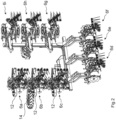
- a soil tillage device 1 designed as a hoe for row crops is in Fig.1 in working position.
- the soil tillage device 1 comprises a frame 2, which has a central base segment 2A and two booms 2B that can be folded to the base segment 2A and extends transversely to the direction of travel F in the working position shown.
- the base segment 2A serves, among other things, to arrange an attachment device 4 by means of which the soil tillage device 1 can be coupled to a towing vehicle (not shown).
- the two booms 2B connect transversely to the direction of travel F to the free ends of the base segment 2A and are arranged in front of the base segment 2A in the direction of travel F.
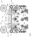
- the booms 2B can be brought from the at least approximately horizontal working position into an upright transport position folded at least approximately by 90 degrees, as in Fig.2
- the hydraulic cylinders 3' are actuated so that their piston rods are retracted, whereby the booms 2B are folded into the transport position about a horizontal axis 5.
- the base segment 2A and the booms 2B are arranged overlapping in the area of the horizontal axes 5 transversely to the direction of travel F.
- the soil tillage device 1 further comprises a plurality of tool carriers 6a - 6i arranged transversely to the direction of travel F on the frame 2.
- the tool carriers 6a - 6i are each arranged on the base segment 2A or one of the booms 2B via a remotely adjustable height control device 7a - 7i and carry soil tillage tools 9a assigned to individual rows of plants 8 as well as soil tillage tools designed as harrows 9b.
- the height control devices 7a - 7i in this soil tillage device 1 comprise a parallelogram suspension 10, which is each controlled by a hydraulic cylinder, in this case Actuator 11 is deformable in an adjustable manner and thus remotely adjustable. Through the targeted deformation of a parallelogram suspension 10 by means of the actuator 11, the associated tool carrier 6a - 6i can be supported at an adjustable height relative to the frame 2.
- the height guide devices 7a - 7i have a detachable fastening device designed as a clamping device at their front free end.
- the tool carriers 6a - 6i can thus be fastened to the base segment 2A and the booms 2B at distances adapted to the row spacing of the plant rows 8.
- the frame 2 can be designed as an H-profile, wherein the clamping device has two fastening claws that encompass the H-profile and can be braced against one another.
- the soil cultivation tools 9a which are assigned to individual rows of plants 8, are designed in this soil cultivation device 1 in the direction of travel F as hoe protection rollers, hoe blades and finger wheels and are supplemented by the trailing harrows 9b.
- the tool carriers 6a - 6i are arranged transversely to the direction of travel F on the frame 2 between two rows of plants 8 to be worked, so that hoe protection rollers and finger wheels arranged on adjacent tool carriers 6a - 6i work a row of plants 8 together and the hoe blades and harrows 9b are guided between two adjacent rows of plants 8.
- the tool carriers 6a - 6i also carry a leading guide wheel 12, via the distance of which from the tool carrier 6a - 6i the working depth of the soil cultivation tools 9a, 9b can be adjusted.
- the distance between the guide wheel 12 and the tool carrier 6a - 6i can be adjusted manually, for example by means of a crank, or can be remotely adjusted, for example hydraulically operated.
- the soil tillage device 1 further comprises two support wheels 14, each arranged via a remotely adjustable swivel device 13 on the side of the frame 2 facing away from the tool carriers 6a - 6i.
- the support wheels 14 are arranged on the booms 2B in this soil tillage device 1 and roll in the working position of the soil tillage device 1 on the ground to be worked, so that the frame 2 rests on it.
- the support wheels 14 can be swiveled up into a lifting position, which removes the ground contact and Fig.2 - 4 shown.
- Fig.1 In the working position of the soil tillage device 1 shown, all tool carriers 6a - 6i are in an intermediate position in which the respective guide wheel 12 rolls on the ground and the actuators 11 are decoupled from the height guide devices 7a - 7i, so that the tool carriers 6a - 6i or the soil tillage tools 9a, 9b attached to them can follow the soil contour by means of the guide wheel 12 interacting with the parallelogram suspension 10.
- the folding device 3 is provided to bring the tool carriers 6a - 6c, 6g - 6i arranged on the booms 2B fold over the tool carriers 6d - 6f arranged on the base segment 2A.
- a coupling control device is provided:
- the folding device 3 and the height guide devices 7d - 7f on the tool carriers 6d - 6f arranged on the base segment 2A are coupled to one another by means of the coupling control device in such a way that each time the booms 2B are moved from the working position into the transport position, the height guide devices 7d - 7f on the tool carriers 6d - 6f arranged on the base segment 2A move the tool carriers 6d - 6f into a position lowered relative to the frame 2.
- the actuators 11 of the height control devices 7d - 7f are preferably completely retracted, so that the parallelogram suspensions 10 extend downwards from the base segment 2A and thus release the installation space for the folding parts of the soil tillage device, particularly in the area above the horizontal axles 5, such as Fig.3 shows.
- the height guide devices 7a - 7i are located essentially below a plane 15A, 15B, 15B ⁇ , which is defined by the longitudinal direction of the frame 2, i.e. the base segment 2A and/or the boom 2B, and the direction of travel F is spanned and thus runs at least approximately horizontally in the working position of the soil tillage device 1.
- the plane 15A, 15B, 15B ⁇ is divided into several sub-planes 15A, 15B, 15B ⁇ by assuming the transport position, namely one sub-plane 15A, 15B, 15B' per frame element 2A, 2B:
- the sub-planes 15A, 15B, 15B' are spanned by the longitudinal direction of the base segment 2A or boom 2B and the direction of travel F, so that the sub-plane 15B, 15B' of a boom 2B in the transport position is at least approximately vertically aligned.
- the height control devices 7a - 7c, 7g - 7i of tool carriers 6a - 6c, 6g - 6i arranged on a boom 2B are also coupled to the coupling control device in such a way that each time a boom 2B is moved from the working position to the transport position, the height control devices 7a - 7c, 7g - 7i of tool carriers 6a - 6c, 6g - 6i arranged on a boom 2B move the tool carriers 6a - 6c, 6g - 6i into a raised position.
- the actuators 11 of the height control devices 7a - 7c, 7g - 7i are preferably fully extended so that the parallelogram suspensions 10 extend upwards from the booms 2B and thus take up the installation space released in the transport position, particularly in the area of the horizontal axes 5.
- the height control devices 7a - 7c, 7g - 7i are located in the raised position essentially above the plane 15A, 15B, 15B ⁇ , which is spanned by the booms 2B and the direction of travel F, as Fig.3 and 4 In the transport position, the height guide devices 7a - 7c, 7g - 7i are thus located between the partial planes 15B, 15B', as Fig.3 "Above" therefore refers less to the direction of gravity than to the fact that the height control devices 7a - 7c, 7g - 7i are moved from the lowered position to the raised position, i.e.
- the soil tillage device 1 thus has a reduced transverse projection in the folded transport position, whereby the height control devices 7a - 7c, 7g - 7i of the tool carriers 6a - 6c, 6g - 6i arranged on the booms 2B can be locked in the transport position.
- An unintentional pivoting of these tool carriers 6a - 6c, 6g - 6i could For example, endangering other road users and is thus effectively avoided.
- the tool carriers 6a - 6i are in the working position of the soil tillage device 1 at least approximately in the lowered position.
- the soil tillage tools 9a, 9b can be raised for each tool carrier 6a - 6i via the height control devices 7a - 7i that interact with the respective tool carriers 6a - 6i.
- the respective tool carrier 6a - 6i is brought into its raised position.
- the lowered and raised positions can have a distance of at least 40 centimeters.
- the height control devices 7a - 7i are thus each set up to move the tool carrier 6a - 6i into positions that are at least 40 centimeters apart.
- the height guide devices 7a - 7i are each designed to lower the circumference of the guide wheel 12 to a distance A below the plane 15A, 15B, 15B', which lies between one and two times the diameter of the guide wheel 12 and/or to raise the circumference of the guide wheel 12 at least approximately into this plane 15A, 15B, 15B'.
- the swivel devices 13, via which the support wheels 14 are arranged in a swiveling manner on the booms 2B, are also coupled to the coupling control device in such a way that each time a boom 2B is moved from the working position to the transport position, the swivel device 13 swivels the respective support wheel 14 into a lifting position.
- the support wheels 14 are located in the lifting position at least partially in the plane 15B, 15B ⁇ , so that the soil tillage device 1 has a further reduced transverse projection in the transport position, as Fig.4 shows.
Landscapes
- Life Sciences & Earth Sciences (AREA)
- Engineering & Computer Science (AREA)
- Mechanical Engineering (AREA)
- Soil Sciences (AREA)
- Environmental Sciences (AREA)
- Zoology (AREA)
- Agricultural Machines (AREA)
Claims (10)
- Engin de travail du sol (1) pour cultures en ligne, comprenant- un cadre (2) s'étendant transversalement à la direction de déplacement (F) en position de travail, qui présente un segment de base (2A) et au moins un bras (2B) pliable par rapport au segment de base (2A),- un dispositif de pliage (3) destiné faire passer l'au moins un bras (2B) pliable entre la position de travail et une position de transport pliée d'au moins approximativement 90 degrés et- une pluralité de porte-outils (6a - 6i) agencés sur le cadre par l'intermédiaire respectivement d'un dispositif de guidage en hauteur (7a - 7i) réglable à distance, des outils de travail du sol (9a) associés à des rangées de plantes (8) individuelles étant agencés sur les porte-outils (6a - 6i),
caractérisé en ce que le dispositif de pliage (3) et au moins les dispositifs de guidage en hauteur (7d - 7f) de porte-outils (6d - 6f) agencés sur le segment de base (2A) sont accouplés entre eux par un dispositif de commande d'accouplement, de préférence hydraulique, de telle sorte qu'à chaque passage d'un bras (2B) depuis la position de travail dans la position de transport, les dispositifs de guidage en hauteur (7d - 7f) de porte-outils (6d - 6f) agencés sur le segment de base (2A) font passer les porte-outils (6d - 6f) dans une position abaissée par rapport au cadre (2). - Engin de travail du sol (1) selon la revendication 1, caractérisé en ce que les dispositifs de guidage en hauteur (7a - 7c, 7g - 7i) de porte-outils (6a - 6c, 6g - 6i) agencés sur un bras (2B) sont accouplés au dispositif de commande d'accouplement de telle sorte qu'à chaque passage d'un bras (2B) depuis la position de travail dans la position de transport, les dispositifs de guidage en hauteur (7a - 7c, 7g - 7i) de porte-outils (6a - 6c, 6g - 6i) agencés sur un bras (2B) font passer les porte-outils (6a - 6c, 6g - 6i) dans une position relevée.
- Engin de travail du sol (1) selon au moins l'une des revendications précédentes, caractérisé en ce que l'engin de travail du sol (1) comprend au moins une roue d'appui (14) qui est agencée sur le cadre (2), en particulier sur un bras (2B), par l'intermédiaire d'un dispositif de pivotement (13) réglable à distance, de préférence sur le côté opposé aux porte-outils (6a - 6i).
- Engin de travail du sol (1) selon la revendication 3, caractérisé en ce que l'au moins un dispositif de pivotement (13) est accouplé au dispositif de commande d'accouplement de telle sorte qu'à chaque passage d'un bras (2B) depuis la position de travail dans la position de transport, le dispositif de pivotement (13) fait pivoter l'au moins une roue d'appui (14) dans une position de déblaiement.
- Engin de travail du sol (1) selon au moins l'une des revendications précédentes, caractérisé en ce que les dispositifs de guidage en hauteur (7a - 7i) sont respectivement conçus pour fait passer les porte-outils (6a - 6i) dans des positions espacées d'au moins 30 centimètres, de préférence d'au moins 40 centimètres.
- Engin de travail du sol (1) selon l'une des revendications précédentes, caractérisé en ce que les dispositifs de guidage en hauteur (7a - 7i) présentent un dispositif de fixation amovible, qui est de préférence réalisé sous la forme d'un dispositif de serrage, pour l'agencement des porte-outils (6a - 6i) sur le cadre (2), de telle sorte que les porte-outils (6a - 6i) peuvent être agencés sur le cadre (2) à des distances réglables, transversalement à la direction de déplacement (F).
- Engin de travail du sol (1) selon la revendication 2, caractérisé en ce qu'au moins les dispositifs de guidage en hauteur (7a - 7c, 7g - 7i) de porte-outils (6a - 6c, 6g - 6i) agencés sur un bras (2B) peuvent être verrouillés, de préférence lorsque l'engin de travail du sol (1) est en position de transport pliée.
- Engin de travail du sol (1) selon l'une des revendications 1, 2 ou 4, caractérisé en ce que le dispositif de commande d'accouplement est réalisé sous la forme d'un circuit hydraulique maître, de telle sorte qu'à chaque passage d'un bras (2B) depuis la position de travail dans la position de transport, les dispositifs de guidage en hauteur (7d - 7f) de porte-outils (6d - 6f) agencés sur le segment de base (2A) peuvent être commandés exclusivement vers la position abaissée, les dispositifs de guidage en hauteur (7a - 7c, 7g - 7i) de porte-outils (6a - 6c, 6g - 6i) agencés sur un bras (2B) peuvent être commandés exclusivement vers la position relevée et/ou le dispositif de pivotement (13) peut être commandé exclusivement vers la position de déblaiement.
- Engin de travail du sol (1) selon au moins l'une des revendications précédentes, caractérisé en ce que le cadre (2) présente le segment de base (2A) et deux bras (2B), en ce que les bras (2B) sont agencés de manière à pouvoir être pliés respectivement autour d'un axe couché (5), dans la direction de déplacement (F) devant le segment de base (2A).
- Engin de travail du sol (1) selon la revendication 9, caractérisé en ce que le segment de base (2A) et les bras (2B) sont agencés de manière superposée, de manière adjacente aux axes couchés (5), en particulier transversalement à la direction de déplacement (F).
Applications Claiming Priority (2)
| Application Number | Priority Date | Filing Date | Title |
|---|---|---|---|
| DE202020103368.9U DE202020103368U1 (de) | 2020-06-11 | 2020-06-11 | Bodenbearbeitungsgerät für Reihenkulturen |
| PCT/EP2021/063793 WO2021249753A1 (fr) | 2020-06-11 | 2021-05-25 | Dispositif de travail du sol pour cultures en rangées |
Publications (3)
| Publication Number | Publication Date |
|---|---|
| EP4164367A1 EP4164367A1 (fr) | 2023-04-19 |
| EP4164367B1 true EP4164367B1 (fr) | 2024-12-04 |
| EP4164367C0 EP4164367C0 (fr) | 2024-12-04 |
Family
ID=71524831
Family Applications (1)
| Application Number | Title | Priority Date | Filing Date |
|---|---|---|---|
| EP21728213.6A Active EP4164367B1 (fr) | 2020-06-11 | 2021-05-25 | Équipement de travail du sol pour les cultures en ligne |
Country Status (6)
| Country | Link |
|---|---|
| US (1) | US20230217846A1 (fr) |
| EP (1) | EP4164367B1 (fr) |
| DE (1) | DE202020103368U1 (fr) |
| HU (1) | HUE069839T2 (fr) |
| PL (1) | PL4164367T3 (fr) |
| WO (1) | WO2021249753A1 (fr) |
Families Citing this family (2)
| Publication number | Priority date | Publication date | Assignee | Title |
|---|---|---|---|---|
| DE102018125940A1 (de) * | 2018-10-18 | 2020-04-23 | Bähr Bau- und Landmaschinen GmbH & Co. KG | Vorrichtung und Verfahren zur mechanischen Unkrautbekämpfung |
| DE102024108317A1 (de) * | 2024-03-22 | 2025-09-25 | Lemken Gmbh & Co. Kg | Landwirtschaftliches Arbeitsgerät |
Family Cites Families (6)
| Publication number | Priority date | Publication date | Assignee | Title |
|---|---|---|---|---|
| FR2780238B1 (fr) * | 1998-06-25 | 2000-09-15 | Kuhn Sa | Semoir comportant des organes de reference, un dispositif d'ancrage automatique et des dispositifs d'appui escamotables limitant le deplacement de structures porteuses |
| BR0301344B1 (pt) * | 2003-04-28 | 2010-02-23 | mecanismo de articulaÇço e travamento dos chassis de implementos agrÍcolas. | |
| DE102004031821A1 (de) * | 2004-07-01 | 2006-01-26 | Amazonen-Werke H. Dreyer Gmbh & Co. Kg | Hydraulische Betätigungsvorrichtung für eine landwirtschaftliche Bearbeitungsmaschine |
| RU2678079C1 (ru) | 2015-03-16 | 2019-01-22 | К.У.Л.Т. Кресс Умвельтшоненде Ландтехник Гмбх | Почвообрабатывающее орудие, способ ведения по высоте по меньшей мере одного рабочего органа пальцевой мотыги над рядком пропашной культуры |
| DE102017116633A1 (de) * | 2017-07-24 | 2019-01-24 | Horsch Maschinen Gmbh | Landwirtschaftliche Bodenbearbeitungsmaschine |
| FR3083664B1 (fr) * | 2018-07-13 | 2020-07-03 | Sarl Eco-Mulch | Chassis pour engin agricole a outils facilement interchangeables |
-
2020
- 2020-06-11 DE DE202020103368.9U patent/DE202020103368U1/de active Active
-
2021
- 2021-05-25 EP EP21728213.6A patent/EP4164367B1/fr active Active
- 2021-05-25 HU HUE21728213A patent/HUE069839T2/hu unknown
- 2021-05-25 US US18/009,166 patent/US20230217846A1/en active Pending
- 2021-05-25 WO PCT/EP2021/063793 patent/WO2021249753A1/fr not_active Ceased
- 2021-05-25 PL PL21728213.6T patent/PL4164367T3/pl unknown
Also Published As
| Publication number | Publication date |
|---|---|
| HUE069839T2 (hu) | 2025-04-28 |
| EP4164367A1 (fr) | 2023-04-19 |
| CA3186501A1 (fr) | 2021-12-16 |
| DE202020103368U1 (de) | 2020-06-18 |
| US20230217846A1 (en) | 2023-07-13 |
| PL4164367T3 (pl) | 2025-03-03 |
| EP4164367C0 (fr) | 2024-12-04 |
| WO2021249753A1 (fr) | 2021-12-16 |
Similar Documents
| Publication | Publication Date | Title |
|---|---|---|
| EP3122168B1 (fr) | Appareil de travail du sol comprenant un dispositif d'étrillage et d'aplanissement | |
| EP1405556A2 (fr) | Faucheuse automoteur à grande largeur de travail | |
| EP4164367B1 (fr) | Équipement de travail du sol pour les cultures en ligne | |
| DE3751912T2 (de) | Bodenbearbeitungsmaschine zur Saatbettherrichtung | |
| EP4104654B1 (fr) | Appareil de traitement du sol à protection hydraulique contre les surcharges | |
| DE102021103040A1 (de) | Zwischenreihenkultivator großer Arbeitsbreite | |
| EP1023825B1 (fr) | Suspension et dispositif de travail ou véhicule | |
| DE3411161C2 (fr) | ||
| DE2220585C3 (de) | Regtungsvorrichtung zur Vertikalverstellung eines an die Kraftheberanlage eines Schleppers angeschlossenen Bodenbearbeitungsgerätes | |
| EP0211967A1 (fr) | Combinaison d'outils de travail de la terre utilisée en agriculture | |
| DE3336313C2 (de) | Bodenstützgerät für eine Landmaschine | |
| EP2232974A1 (fr) | Dispositif agricole accouplable à un tracteur | |
| DE10120845B4 (de) | Hydromechanische Steuerungsvorrichtung für eine mehrteilige landwirtschaftliche Arbeitsmaschine | |
| EP2944170A1 (fr) | Épandeur agricole, en particulier semoir, et procédé de réglage en hauteur des socs | |
| EP2113159A1 (fr) | Cultivateur | |
| EP3912444A1 (fr) | Dispositif de montage pour appareils de travail agricoles | |
| DE3535683A1 (de) | Bodenbearbeitungsgeraet fuer die landwirtschaft | |
| EP0594160A1 (fr) | Machine à utiliser dans des pépinières, jardins et analogues | |
| EP4298880B1 (fr) | Bras oscillant pour machine agricole | |
| EP4278875B1 (fr) | Outil pour la culture des champs | |
| EP3311640A1 (fr) | Dispositif d'attelage pour un véhicule tracteur agricole et son procédé de fonctionnement | |
| DE8717049U1 (de) | Geräteantriebsaggregat für landwirtschaftliche Zwecke | |
| EP4305938A1 (fr) | Outil de travail du sol | |
| WO1998047344A2 (fr) | Porte-outils pour machines de labourage et de travail du sol | |
| EP4662991A1 (fr) | Porte-outil |
Legal Events
| Date | Code | Title | Description |
|---|---|---|---|
| STAA | Information on the status of an ep patent application or granted ep patent |
Free format text: STATUS: UNKNOWN |
|
| STAA | Information on the status of an ep patent application or granted ep patent |
Free format text: STATUS: THE INTERNATIONAL PUBLICATION HAS BEEN MADE |
|
| PUAI | Public reference made under article 153(3) epc to a published international application that has entered the european phase |
Free format text: ORIGINAL CODE: 0009012 |
|
| STAA | Information on the status of an ep patent application or granted ep patent |
Free format text: STATUS: REQUEST FOR EXAMINATION WAS MADE |
|
| 17P | Request for examination filed |
Effective date: 20221121 |
|
| AK | Designated contracting states |
Kind code of ref document: A1 Designated state(s): AL AT BE BG CH CY CZ DE DK EE ES FI FR GB GR HR HU IE IS IT LI LT LU LV MC MK MT NL NO PL PT RO RS SE SI SK SM TR |
|
| P01 | Opt-out of the competence of the unified patent court (upc) registered |
Effective date: 20230523 |
|
| DAV | Request for validation of the european patent (deleted) | ||
| DAX | Request for extension of the european patent (deleted) | ||
| GRAP | Despatch of communication of intention to grant a patent |
Free format text: ORIGINAL CODE: EPIDOSNIGR1 |
|
| STAA | Information on the status of an ep patent application or granted ep patent |
Free format text: STATUS: GRANT OF PATENT IS INTENDED |
|
| INTG | Intention to grant announced |
Effective date: 20240703 |
|
| GRAS | Grant fee paid |
Free format text: ORIGINAL CODE: EPIDOSNIGR3 |
|
| GRAA | (expected) grant |
Free format text: ORIGINAL CODE: 0009210 |
|
| STAA | Information on the status of an ep patent application or granted ep patent |
Free format text: STATUS: THE PATENT HAS BEEN GRANTED |
|
| AK | Designated contracting states |
Kind code of ref document: B1 Designated state(s): AL AT BE BG CH CY CZ DE DK EE ES FI FR GB GR HR HU IE IS IT LI LT LU LV MC MK MT NL NO PL PT RO RS SE SI SK SM TR |
|
| REG | Reference to a national code |
Ref country code: CH Ref legal event code: EP |
|
| REG | Reference to a national code |
Ref country code: DE Ref legal event code: R096 Ref document number: 502021006009 Country of ref document: DE |
|
| REG | Reference to a national code |
Ref country code: IE Ref legal event code: FG4D Free format text: LANGUAGE OF EP DOCUMENT: GERMAN |
|
| U01 | Request for unitary effect filed |
Effective date: 20241224 |
|
| U07 | Unitary effect registered |
Designated state(s): AT BE BG DE DK EE FI FR IT LT LU LV MT NL PT RO SE SI Effective date: 20250114 |
|
| P04 | Withdrawal of opt-out of the competence of the unified patent court (upc) registered |
Free format text: CASE NUMBER: APP_1578/2025 Effective date: 20250110 |
|
| PG25 | Lapsed in a contracting state [announced via postgrant information from national office to epo] |
Ref country code: HR Free format text: LAPSE BECAUSE OF FAILURE TO SUBMIT A TRANSLATION OF THE DESCRIPTION OR TO PAY THE FEE WITHIN THE PRESCRIBED TIME-LIMIT Effective date: 20241204 |
|
| PG25 | Lapsed in a contracting state [announced via postgrant information from national office to epo] |
Ref country code: ES Free format text: LAPSE BECAUSE OF FAILURE TO SUBMIT A TRANSLATION OF THE DESCRIPTION OR TO PAY THE FEE WITHIN THE PRESCRIBED TIME-LIMIT Effective date: 20241204 |
|
| PG25 | Lapsed in a contracting state [announced via postgrant information from national office to epo] |
Ref country code: NO Free format text: LAPSE BECAUSE OF FAILURE TO SUBMIT A TRANSLATION OF THE DESCRIPTION OR TO PAY THE FEE WITHIN THE PRESCRIBED TIME-LIMIT Effective date: 20250304 |
|
| PG25 | Lapsed in a contracting state [announced via postgrant information from national office to epo] |
Ref country code: GR Free format text: LAPSE BECAUSE OF FAILURE TO SUBMIT A TRANSLATION OF THE DESCRIPTION OR TO PAY THE FEE WITHIN THE PRESCRIBED TIME-LIMIT Effective date: 20250305 |
|
| REG | Reference to a national code |
Ref country code: HU Ref legal event code: AG4A Ref document number: E069839 Country of ref document: HU |
|
| PG25 | Lapsed in a contracting state [announced via postgrant information from national office to epo] |
Ref country code: RS Free format text: LAPSE BECAUSE OF FAILURE TO SUBMIT A TRANSLATION OF THE DESCRIPTION OR TO PAY THE FEE WITHIN THE PRESCRIBED TIME-LIMIT Effective date: 20250304 |
|
| U20 | Renewal fee for the european patent with unitary effect paid |
Year of fee payment: 5 Effective date: 20250407 |
|
| PG25 | Lapsed in a contracting state [announced via postgrant information from national office to epo] |
Ref country code: SM Free format text: LAPSE BECAUSE OF FAILURE TO SUBMIT A TRANSLATION OF THE DESCRIPTION OR TO PAY THE FEE WITHIN THE PRESCRIBED TIME-LIMIT Effective date: 20241204 |
|
| PG25 | Lapsed in a contracting state [announced via postgrant information from national office to epo] |
Ref country code: IS Free format text: LAPSE BECAUSE OF FAILURE TO SUBMIT A TRANSLATION OF THE DESCRIPTION OR TO PAY THE FEE WITHIN THE PRESCRIBED TIME-LIMIT Effective date: 20250404 |
|
| PGFP | Annual fee paid to national office [announced via postgrant information from national office to epo] |
Ref country code: HU Payment date: 20250429 Year of fee payment: 5 |
|
| PG25 | Lapsed in a contracting state [announced via postgrant information from national office to epo] |
Ref country code: SK Free format text: LAPSE BECAUSE OF FAILURE TO SUBMIT A TRANSLATION OF THE DESCRIPTION OR TO PAY THE FEE WITHIN THE PRESCRIBED TIME-LIMIT Effective date: 20241204 |
|
| PGFP | Annual fee paid to national office [announced via postgrant information from national office to epo] |
Ref country code: CZ Payment date: 20250430 Year of fee payment: 5 |
|
| PLBE | No opposition filed within time limit |
Free format text: ORIGINAL CODE: 0009261 |
|
| STAA | Information on the status of an ep patent application or granted ep patent |
Free format text: STATUS: NO OPPOSITION FILED WITHIN TIME LIMIT |
|
| REG | Reference to a national code |
Ref country code: CH Ref legal event code: L10 Free format text: ST27 STATUS EVENT CODE: U-0-0-L10-L00 (AS PROVIDED BY THE NATIONAL OFFICE) Effective date: 20251015 |
|
| 26N | No opposition filed |
Effective date: 20250905 |
|
| REG | Reference to a national code |
Ref country code: CH Ref legal event code: H13 Free format text: ST27 STATUS EVENT CODE: U-0-0-H10-H13 (AS PROVIDED BY THE NATIONAL OFFICE) Effective date: 20251223 |
|
| PG25 | Lapsed in a contracting state [announced via postgrant information from national office to epo] |
Ref country code: CH Free format text: LAPSE BECAUSE OF NON-PAYMENT OF DUE FEES Effective date: 20250531 |
|
| PG25 | Lapsed in a contracting state [announced via postgrant information from national office to epo] |
Ref country code: MC Free format text: LAPSE BECAUSE OF FAILURE TO SUBMIT A TRANSLATION OF THE DESCRIPTION OR TO PAY THE FEE WITHIN THE PRESCRIBED TIME-LIMIT Effective date: 20241204 |
|
| PGFP | Annual fee paid to national office [announced via postgrant information from national office to epo] |
Ref country code: GB Payment date: 20260312 Year of fee payment: 6 |
|
| PG25 | Lapsed in a contracting state [announced via postgrant information from national office to epo] |
Ref country code: IE Free format text: LAPSE BECAUSE OF NON-PAYMENT OF DUE FEES Effective date: 20250525 |
|
| PGFP | Annual fee paid to national office [announced via postgrant information from national office to epo] |
Ref country code: PL Payment date: 20260313 Year of fee payment: 6 |