EP4164833B1 - Verfahren und system zum laserschweissen eines halbleitermaterials - Google Patents
Verfahren und system zum laserschweissen eines halbleitermaterials Download PDFInfo
- Publication number
- EP4164833B1 EP4164833B1 EP21737344.8A EP21737344A EP4164833B1 EP 4164833 B1 EP4164833 B1 EP 4164833B1 EP 21737344 A EP21737344 A EP 21737344A EP 4164833 B1 EP4164833 B1 EP 4164833B1
- Authority
- EP
- European Patent Office
- Prior art keywords
- workpiece
- laser
- laser radiation
- workpieces
- focus
- Prior art date
- Legal status (The legal status is an assumption and is not a legal conclusion. Google has not performed a legal analysis and makes no representation as to the accuracy of the status listed.)
- Active
Links
Images

Classifications
-
- B—PERFORMING OPERATIONS; TRANSPORTING
- B23—MACHINE TOOLS; METAL-WORKING NOT OTHERWISE PROVIDED FOR
- B23K—SOLDERING OR UNSOLDERING; WELDING; CLADDING OR PLATING BY SOLDERING OR WELDING; CUTTING BY APPLYING HEAT LOCALLY, e.g. FLAME CUTTING; WORKING BY LASER BEAM
- B23K26/00—Working by laser beam, e.g. welding, cutting or boring
- B23K26/50—Working by transmitting the laser beam through or within the workpiece
- B23K26/57—Working by transmitting the laser beam through or within the workpiece the laser beam entering a face of the workpiece from which it is transmitted through the workpiece material to work on a different workpiece face, e.g. for effecting removal, fusion splicing, modifying or reforming
-
- B—PERFORMING OPERATIONS; TRANSPORTING
- B23—MACHINE TOOLS; METAL-WORKING NOT OTHERWISE PROVIDED FOR
- B23K—SOLDERING OR UNSOLDERING; WELDING; CLADDING OR PLATING BY SOLDERING OR WELDING; CUTTING BY APPLYING HEAT LOCALLY, e.g. FLAME CUTTING; WORKING BY LASER BEAM
- B23K26/00—Working by laser beam, e.g. welding, cutting or boring
- B23K26/20—Bonding
- B23K26/21—Bonding by welding
-
- B—PERFORMING OPERATIONS; TRANSPORTING
- B23—MACHINE TOOLS; METAL-WORKING NOT OTHERWISE PROVIDED FOR
- B23K—SOLDERING OR UNSOLDERING; WELDING; CLADDING OR PLATING BY SOLDERING OR WELDING; CUTTING BY APPLYING HEAT LOCALLY, e.g. FLAME CUTTING; WORKING BY LASER BEAM
- B23K26/00—Working by laser beam, e.g. welding, cutting or boring
- B23K26/02—Positioning or observing the workpiece, e.g. with respect to the point of impact; Aligning, aiming or focusing the laser beam
- B23K26/04—Automatically aligning, aiming or focusing the laser beam, e.g. using the back-scattered light
- B23K26/046—Automatically focusing the laser beam
-
- B—PERFORMING OPERATIONS; TRANSPORTING
- B23—MACHINE TOOLS; METAL-WORKING NOT OTHERWISE PROVIDED FOR
- B23K—SOLDERING OR UNSOLDERING; WELDING; CLADDING OR PLATING BY SOLDERING OR WELDING; CUTTING BY APPLYING HEAT LOCALLY, e.g. FLAME CUTTING; WORKING BY LASER BEAM
- B23K26/00—Working by laser beam, e.g. welding, cutting or boring
- B23K26/20—Bonding
- B23K26/21—Bonding by welding
- B23K26/24—Seam welding
- B23K26/244—Overlap seam welding
-
- B—PERFORMING OPERATIONS; TRANSPORTING
- B23—MACHINE TOOLS; METAL-WORKING NOT OTHERWISE PROVIDED FOR
- B23K—SOLDERING OR UNSOLDERING; WELDING; CLADDING OR PLATING BY SOLDERING OR WELDING; CUTTING BY APPLYING HEAT LOCALLY, e.g. FLAME CUTTING; WORKING BY LASER BEAM
- B23K26/00—Working by laser beam, e.g. welding, cutting or boring
- B23K26/20—Bonding
- B23K26/32—Bonding taking account of the properties of the material involved
- B23K26/324—Bonding taking account of the properties of the material involved involving non-metallic parts
-
- B—PERFORMING OPERATIONS; TRANSPORTING
- B23—MACHINE TOOLS; METAL-WORKING NOT OTHERWISE PROVIDED FOR
- B23K—SOLDERING OR UNSOLDERING; WELDING; CLADDING OR PLATING BY SOLDERING OR WELDING; CUTTING BY APPLYING HEAT LOCALLY, e.g. FLAME CUTTING; WORKING BY LASER BEAM
- B23K2103/00—Materials to be soldered, welded or cut
- B23K2103/50—Inorganic materials other than metals or composite materials
- B23K2103/56—Inorganic materials other than metals or composite materials being semiconducting
Definitions
- EP 2 745 975 A1 discloses a system for laser welding of two workpieces, in which the focus of the laser beam is varied along the beam direction.
- a measuring unit is provided that measures a displacement of the focus.
- the laser beam passing through one of the workpieces is controlled to have its focal point in the common surface of the two workpieces. The energy of the laser beam thus melts material of the two workpieces, and the two workpieces are welded together.
- a method for welding a first workpiece to a second workpiece by means of a laser comprises the steps of:
- a permanent modification at the interface between the two workpieces is achieved by the approach of the invention with the exit surface of the semiconductor workpiece being mechanically and/or optically in contact with the second workpiece.
- the laser flux is absorbed to a maximum extent at the interface between the two workpieces as a re-localization procedure of the intensity maximum is performed so as to compensate for the nonlinear propagation of the laser beam through the semiconductor workpiece.
- the laser welding process is optimized by this approach in terms of bonding strength.
- the method of the invention is divided into two main sections.
- the first workpiece is irradiated with the pulsed laser radiation with the radiation being focused at the exit surface of the first workpiece, which is to form the interface with the second workpiece.
- an intensity delocalization occurs, i.e., a shift of the intensity maximum along the beam path to a position upstream of the actual geometric focus at the exit surface.
- This delocalization is determined in the first section of the method of the invention, e.g. by measuring the variation of the intensity of the irradiated laser radiation along the beam path to find the position of maximum intensity within the first workpiece.
- the actual welding process takes place.
- the second workpiece is placed against the first workpiece at its exit surface.
- the two workpieces may be maintained in position either with or without a suitable assembling method such as optical contact or mechanical fixture (e.g., glue).
- the focus of the laser beam is re-positioned along the beam path taking the measured delocalization into account such that the intensity maximum is located precisely in the plane of the interface between the two workpieces.
- the assembly of the two workpieces is then irradiated in this corrected configuration such that the delocalization is compensated for, and the two workpieces are firmly bonded.
- welding within the meaning of the invention refers to any process providing a laser-induced bond between the two workpieces, i.e. a force maintaining the two workpieces in mechanical contact.
- the laser radiation is formed by a single pulse or a pulse train with a pulse duration between 1 fs and 100 ns.
- a pulse train is defined as a group of several individual pulses temporally separated.
- the term "pulse" is used herein both for a laser irradiation constituted by a single laser pulse or a train of laser pulses.
- E in the pulse energy ⁇ is the pulse duration taken at full-width at half-maximum
- w 0 is the beam radius at the focus (taken at an intensity drop of 1/e 2 ) in the case of a bell-shaped beam (e.g., a Gaussian beam).
- the duration of the irradiation corresponds to the time interval starting with the maximum intensity of the first laser pulse and ending with the maximum intensity of the last laser pulse; and the pulse energy is defined as the average power during the train multiplied by the duration of the train.
- the parameters of the laser radiation are identical during the determination of the delocalization and during welding the first workpiece to the second workpiece.
- the selection of identical radiation parameters during both sections ensures that the intensity maximum of the laser radiation is located precisely at the interface between the two workpieces so as to obtain an optimal bond.
- the material of the second workpiece is opaque at the wavelength of the laser radiation.
- the method of the invention is particularly well suited for welding a transparent semiconductor material to material (e.g. a metal) that is opaque at the wavelength of the laser radiation.
- the laser radiation is absorbed at the interface between the two workpieces and thus induces a material modification during the welding process.
- Transparency and opacity of a workpiece are defined by comparing the photon energy of the laser radiation (at a given wavelength) with the band gap of the material of the respective workpiece.
- semiconductor refers to a band gap material, i.e., a material with a valence band and a conduction band separated by an energy range where no electron state exists (in the ideal case of defect-free semiconductor) and where the Fermi level is located. Both the valence and the conduction band are close enough to this level so they are populated with electrons or holes.
- the wavelength ⁇ of the laser radiation is preferably selected in the interval satisfying: ⁇ 2 ⁇ hc / ⁇ ⁇ ⁇ 1 .
- the band gap values are given in electron-volts (1 eV ⁇ 1,6022 ⁇ 10 -19 J).
- the placing of the second workpiece against the first workpiece may involve an optical contact, a loose stacking, or a mechanical fixturing, as appropriate in terms of workpiece condition, i.e., surface roughness, workpiece size etc.
- the assembly formed by the two workpieces is relatively moved in a plane perpendicular with respect to the laser beam during the welding process to create a welding pattern.
- the number of laser pulses per welding point of the welding pattern may be controlled by controlling the repetition rate of the laser and/or the speed of the relative movement of the laser beam and the workpieces during welding.
- the beam size at the interface between the two workpieces and the laser intensity per pulse may be varied for optimizing the bonding force between the two workpieces. For example, a gradual increase of the laser intensity at the interface between the two workpieces starting from a predetermined value may be useful to obtain a maximum bonding force.
- a multi-scan welding procedure may be useful, with or without a variation of the laser intensity between different scans of the same zone at the interface between the two workpieces.
- the focus of the laser radiation is moved along the interface between the two workpieces to create a welding pattern. This may involve a simultaneous relative movement of the laser beam and the assembly of the two workpieces along the optical axis as well as along the axes perpendicular thereto.
- the positioning device enables the intensity maximum of the laser radiation to be positioned at the interface between the two workpieces based on the determined delocalization of the focus.
- the positioning device further enables the relative movement of the assembly of the two workpieces in the plane perpendicular to the laser beam during welding, e.g. for generating a suitable welding pattern by scanning the laser beam across the assembly formed by the two workpieces.
- the positioning device may comprise galvanometer mirrors, scanning mirrors, a beam steering phased array, a translation stage, a rotation stage and/or a piezoelectric stage.
- the measuring device comprises a microscope arranged on the side of the exit surface of the first workpiece, the observation direction of the microscope being essentially opposite (anti-parallel) to the propagation direction of the laser beam.
- This also includes a variant in which a small angle (e.g., in the range of 0-10°) is introduced between the observation direction of the microscope and the propagation direction of the laser beam).
- the microscope may comprise an objective lens and a camera.
- the intensity variation along the beam path can be imaged/scanned by moving relatively the focal plane of the microscope along the beam path within the material of the first workpiece to determine the position of maximum intensity.
- the beam controlling device is configured to control the parameters of the laser radiation, specifically the spectrum, the pulse duration, the temporal pulse shape, the beam size, the polarization and/or the pulse energy.
- the beam controlling device is constituted by a number of sub-modules.
- a sub-module used for focusing the laser radiation may comprise objective lenses, spherical lenses, aspherical lenses, F-Theta lenses, cylindrical lenses, and/or parabolic mirrors.
- a further sub-module of the beam controlling device may comprise an optical parametric amplifier, an optical parametric oscillator, a frequency converting crystal for controlling the wavelength of the laser radiation.
- Yet another sub-module may comprise a stretcher based on a combination of dispersive elements such as gratings or prisms for controlling the pulse duration.
- a sub-module comprising a spatial light modulator may be employed for controlling the spatial distribution of the laser beam, a Keplerian or a Galilean telescope made of a combination of lenses and/or parabolic mirrors may be used as a further sub-module for controlling the beam size.
- a sub-module comprising a combination of polarizers and/or waveplates may be employed for controlling the polarization of the laser beam, and/or a combination of waveplates, polarizers and/or neutral density filters may constitute a sub-module for controlling the pulse energy.
- the pulse energy, polarization and repetition rate may be controlled using an acousto-optic modulator (AOM) or an electro-optic modulator (EOM).
- AOM acousto-optic modulator
- EOM electro-optic modulator
- the system further comprises an observation device configured to inspect the entrance surface of the first workpiece.
- the observation device makes it possible, e.g., to observe concomitance of the entrance surface of the first workpiece with the geometric focus of the laser beam such that the precise relative position of the workpiece and the focus can be determined.
- the observation device may comprise a dark-field or a bright-field microscope or a phase-contrast microscope working either in transmission or reflection.
- the system comprises a conditioning device configured to control the ambient conditions of the assembly of the two workpieces.
- the conditioning device controls the environment of the welding process in terms of chemical composition, pressure and temperature. It may include a gas-tight chamber in which the assembly of the two workpieces is arranged, wherein the chamber can be connected to a vacuum pump and to one or more gas reservoirs to establish a desired gas composition within the chamber.
- a heating device (an oven) may be used to control the ambient temperature during welding.
- the two workpieces are subject to the welding process carried out by the system of the invention and are therefore not part or component of the system itself.
- a system 100 for welding a first workpiece 11 to a second workpiece 12 is shown as a block diagram.
- the first workpiece 11 consists of a semiconductor material, e.g. silicon.
- the material of the second workpiece is a metal, e.g. copper.
- the two workpieces 11, 12 may or may not be in optical contact at their common interface.
- the optional optical contact can be established by introducing a suitable fluid within the gap between the two workpieces 11, 12, such as, e.g., methanol, ethanol, etc.
- the workpieces 11, 12 can be maintained in contact by means of any common mechanical fixturing method.
- the laser welding system 100 includes in particular a laser device 21, e.g. a mode locked fiber laser in combination with one or more optical amplification stages, which emits pulsed laser radiation 201 with given properties in terms of spatial and temporal distribution, polarization, energy, spectrum, repetition rate, etc.
- a beam controlling device 20 is provided for controlling the characteristics of the laser pulses 201 in terms of wavelength, pulse duration, temporal pulse shape, repetition rate, spatial distribution of the beam, beam size, pulse energy, and polarization before being directed through the first workpiece 11.
- the beam controlling device 20 comprises several sub-modules 22-26 for controlling the pulse characteristics and a focusing optics 40 to focus the laser beam, which enters through an entrance surface of the workpiece 11 and leaves it through an exit surface forming the interface between the two workpieces 11, 12, with the geometric focus being set at a location along the beam path.
- the focusing optics 40 can include, e.g., an objective lens, a convex single lens, a parabolic mirror, an aspherical lens, an F-Theta lens, a cylindrical lens, etc.
- the relative position of the assembly 10 of the two workpieces 11, 12 with respect to the incoming focused beam is adjusted by a positioning device 50 (e.g., a translation stage, a rotation stage, a piezoelectric stage, or a combination of these) enabling the displacement of the assembly 10 in the direction of the laser beam (in order to adapt the position of the geometric focus) as well as in the plane perpendicular thereto.
- a positioning device 50 e.g., a translation stage, a rotation stage, a piezoelectric stage, or a combination of these
- a positioning device 50 e.g., a translation stage, a rotation stage, a piezoelectric stage, or a combination of these
- a positioning device 50 e.g., a translation stage, a rotation stage, a piezoelectric stage, or a combination of these
- a positioning device 50 e.g., a translation stage, a rotation stage, a piezoelectric stage, or a combination of these
- the welding pattern is determined by a scanning strategy to obtain, e.g., a point-by-point pattern, a line-by-line pattern, a concentric circle pattern, a spiral pattern, single-scan, multi-scan with or without increase in laser intensity between the scans, etc.
- the scanning speed during welding is between 1 nm/s and 10 m/s.
- the welding pattern can be chosen as a function of the amount of energy deposited per point of the welding pattern at the interface between the two workpieces 11, 12 which mainly depends on the laser repetition rate, pulse energy, and beam size.
- the system 100 further comprises an observation device 30 for inspecting at least one of the surfaces of the first workpiece 11.
- the observation device 30 can be, e.g., an optical bright-field or dark-field microscope either working in transmission or in reflection, with or without phase contrast.
- the observation device 30 enables monitoring of the interaction of the laser radiation at the respective surface of the first workpiece 11 for precise calibration of the positioning of the geometric focus of the laser beam relative to the surfaces of the workpiece 11.
- the system 100 further includes a conditioning device 60 for controlling the ambient conditions of the welding process in terms of chemical composition, pressure, and temperature.
- the conditioning device 60 includes, for example, a chamber with a valve for gas injection, a vacuum chamber connected to vacuum pumps, an oven, etc.
- the beam controlling device 20 includes optional sub-modules 22-26 for tailoring the laser pulse properties.
- the first optional sub-module 22 is provided for controlling the wavelength, and, more generally, the spectral characteristics of the pulses.
- Module 22 can be, for example, an optical parametric amplifier (OPA), an optical parametric oscillator (OPO), a frequency doubling crystal, etc.
- OPA optical parametric amplifier
- OPO optical parametric oscillator
- the wavelength of the pulses 202 at the output of module 22 has to be adjusted so that workpiece 11 is transparent at this wavelength, whereas workpiece 12 is opaque at this wavelength.
- an adjusted wavelength of 1.55 ⁇ m is appropriate if the material of workpiece sample 11 is crystalline silicon, and the material of workpiece 12 is a metal (e.g., copper, gold, silver, aluminum, etc.).
- the second optional module 23 is provided for controlling the temporal shape of the laser pulses, in accordance with a predefined welding pattern.
- the module 23 can decrease the repetition rate of the pulses 202, and can be, for example, an optical beam shutter, an optical chopper, a Pockels cell, an acousto-optic modulator (AOM), etc.
- the module 23 gives access to the control of the pulse duration, and can be, for example, a stretcher or a compressor composed of a combination of various dispersive elements such as diffraction gratings or prisms, or a pulse stretcher based on group velocity dispersion in a given material.
- the third optional module 24 is provided for controlling the spatial distribution of the beam. It can increase or decrease the beam size, e.g., by means of a Galilean or a Keplerian telescope, and, more generally, any afocal system. Secondly, module 24 can change the beam profile (i.e., the spatial beam distribution) from the beam at the input 203 to the output 204. E.g., module 24 can be able to generate Gaussian, tophat (i.e., uniform in intensity), Bessel or vortex beams. Module 24 can include an axicon, phase plates, a spatial light modulator, etc.
- the fourth optional module 25 enables the control of the polarization of the laser beam, i.e., the direction of the electric field of the laser.
- Module 25 can include, for example, wave plates (half-wave plate, quarter-wave plate), polarizers (e.g., linear polarizer, radial polarizer, electro-optic modulator), etc.
- the fifth and last optional module 26 is provided for the control of the pulse energy by decreasing the beam power from the entrance 205 to the exit 206 of this module.
- the attenuation in pulse energy can be carried out with, for example, an optical attenuator, neutral density filters, the combination of a half-wave plate and a polarizer (the control of the energy is achieved by rotating the half-wave plate in this case), etc.
- the spectral, temporal, spatial, polarization and energy characteristics of the beam 206 can be optimally tailored.
- the sequence of the sub-modules 22-26 may be modified as required.
- the laser pulse energy can be estimated by applying an energy calibration procedure. This procedure consists of measuring the average power of the laser radiation, e.g. using a power meter, between the focusing optics 40 and the workpiece 11. The corresponding pulse energy can be easily determined by calculating the ratio between the measured average power value (in Watts) and the repetition rate of the laser (i.e., the number of laser pulses per second, in Hertz). Furthermore, the energy after propagation through the entrance surface of the workpiece 11 can be estimated by multiplying the pulse energy with the Fresnel transmission coefficient calculated from the refractive indices of the environment and the workpiece 11, the laser polarization and the angle of incidence of the laser beam.
- an energy calibration procedure consists of measuring the average power of the laser radiation, e.g. using a power meter, between the focusing optics 40 and the workpiece 11.
- the corresponding pulse energy can be easily determined by calculating the ratio between the measured average power value (in Watts) and the repetition rate of the laser (i.e., the number of
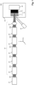
- FIG 2 shows a depiction of the measuring device 70 of the system 100.
- the measuring device 70 is used to measure the variation of the intensity of the laser radiation along the beam path within the first workpiece 11 to determine a delocalization of the focus caused by nonlinear interaction of the laser radiation with the semiconductor material of workpiece 11. This measuring procedure is carried out before the actual welding.
- the measuring procedure includes the focusing of the laser beam with identical beam parameters as used in welding (in terms of spectrum, temporal profile, pulse duration, spatial distribution of the beam, beam size, polarization, and pulse energy).
- the laser beam is initially focused on the exit surface of the first workpiece 11 that has to be laser welded to the second workpiece 12 ( Figure 1 ) afterwards.
- the measuring device 70 a microscope collinear to the optical axis Z and directed oppositely to the laser beam direction, enables imaging of the exit surface of the workpiece 11. Due to the fact that the imaging system 70 is also centered on the beam focused by the focusing system 40, the measuring device 70 is able to image the spatial distribution of the beam intensity at the exit surface of workpiece 11.
- the measuring device 70 is composed of a collecting optics 71 whose numerical aperture (NA) is ideally higher than the one of the focusing optics 40 for ensuring to collect all angular components of the incoming light.
- the collecting optics 71 can be, for example, an infinity-corrected objective lens. In this way, the beam is collimated after being collected by the focusing optics 40.
- An optional tube optics 72 is provided to refocus the collimated light onto a camera 73 that can be equipped, for example, with a bandpass filter for ensuring that only the light at the wavelength of the laser radiation is detected. This filter can be particularly relevant in the case of third-harmonic generation in the material, as well as for blocking most of the ambient light.
- the tube optics 72 can be bypassed and the beam is directly refocused on the camera 73.
- the camera 73 has a linear response at the wavelength of the incoming laser.
- the image on the camera 73 should not show any saturated pixels during measurement.
- the system 100 further includes a linear translation stage 80 enabling relative displacement of the focusing optics 40 only along the optical axis Z, upstream as well as downstream along the laser beam path.
- the translation stage 80 enables the workpiece 11 and the measuring device 70 to move together along the optical axis Z, with a fixed position of the focusing optics 40.
- the arrangement shown in Figure 2 enables to image the spatial distribution of the incoming laser light in the (X,Y) plane for various relative positions of the focus along the optical axis Z with respect to the exit surface of the workpiece 11.
- a first beam propagation imaging procedure can be carried out at a pulse energy for which the beam propagation is linear, i.e. without nonlinear interaction of the laser radiation with the semiconductor material of the first workpiece 11 (typically at a pulse energy between 1 fJ and 20 pJ, depending on the sensitivity of the camera 73).
- the energy can be attenuated to such a low level by means of, for example, neutral density filters of module 26 (see Figure 1 ).
- the same measurement is performed at the pulse energy at which the welding procedure is to be carried out.
- the intensity corresponding to this pulse energy has to be sufficient for inducing a material modification at the interface between the two workpieces 11, 12 during the laser welding procedure.
- the linear and the nonlinear propagation images acquired by measuring device 70 can be analyzed to determine the position of maximum pixel amplitude along the optical axis Z (which is related to the maximum fluence and intensity of the laser beam).
- the difference between the positions of maximum intensity along the optical axis Z in the linear and nonlinear propagation cases (designated herein below as ⁇ Z) can be derived from a comparison of the two images.
- the position of the maximum intensity is strongly shifted upstream along the beam path, i.e., in the pre-focal region of the bulk semiconductor material.
- This is physically related to soliton formation provoked by the competition of nonlinear phenomena such as Kerr-induced self-focusing, plasma formation (due to, e.g., multi-photon absorption, avalanche ionization, tunnel ionization, etc.), and plasma defocusing.
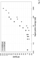
- Figure 3 illustrates an experimental quantification of the evolution of the nonlinear propagation-induced shift ⁇ Z along the optical axis as a function of the pulse energy (measured in air before the entrance surface of the first workpiece 11). It can be seen from the diagram of Figure 3 that, for 0.86-ps pulses at low energy (i.e., ⁇ 6 nJ), ⁇ Z is close to zero, showing the linear propagation of the laser radiation at these energies. In the energy range 6-100 nJ, ⁇ Z monotonically increases with increasing pulse energy, indicating that nonlinear propagation phenomena start to become prominent. A similar behavior is observed for 9.83-ps duration pulses, but shifted toward higher pulse energies.
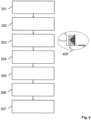
- Figure 4 represents a flow chart of an exemplary embodiment of the method of the invention.
- step 301 the shift ⁇ Z of the geometric focus induced by the nonlinear propagation is determined by irradiating the first workpiece 11 only as described above with reference to Figures 2 and 3 .
- step 302 the second workpiece 12 is placed against the first workpiece 11 to bring the two workpieces 11, 12 in mechanical and/or optical contact.
- step 303 a calibration of the relative positioning of the laser beam focus and the surfaces of the first workpiece 11 is carried out. To this end, the entrance surface of the first workpiece 11 is observed (using observation device 30, see Figure 1 ).
- the precise position (of the focusing optics 40 or the workpiece 11) along the optical axis Z at which the geometric focus coincides with the entrance surface of the first workpiece 11 is determined (designated as Z entrance ).
- This determination can be achieved by a destructive Z-scan procedure schematically illustrated at 400.
- the Z-scan procedure consists of creating a matrix of irradiated sites on the entrance surface of workpiece 11. The columns of the matrix correspond to different pulse energies, and the lines of the matrix correspond to different Z positions of the focusing optics 40 (or vice-versa).
- the Z entrance position is the one of the matrix line for which a single damage (black spots in the diagram 400) is observed for a specific pulse energy (corresponding to the damage threshold of the material of the first workpiece 11).
- the Z-calibration thus results from observation of the damage sites produced at the entrance surface of the first workpiece 11.
- a (residual) tilt of the workpiece 11 with respect to the focusing optics 40 may exist in practice. This tilt is determined in step 304. While this tilt is usually small (on the order of 1- ⁇ m difference along Z for a displacement of 100 ⁇ m in the X or Y direction), this can lead to a significant error when a mm- or cm-size semiconductor sample has to be welded to an opaque material sample. This is even more pronounced for a high refractive index of the semiconductor material, due to refraction.
- a 1 mm displacement along Z corresponds to an actual displacement in crystalline silicon of about 3.5 mm at a wavelength of 1300 nm (where the refractive index of silicon is 3.5).
- the thickness and topography of the first workpiece in which the laser radiation propagates has to be taken into account.
- the Z entrance position has to be determined as described above at three different positions. These positions can be chosen, e.g., at the starting point of the laser welding pattern, at the maximum X position, and at the maximum Y position.
- the geometric focus is positioned in the Z direction at the interface (Z interface position) between the two workpieces 11, 12 in step 305.
- This is straightforward after determination of Z entrance , knowing the refractive index of the semiconductor material of the first workpiece 11 at the welding wavelength as well as its thickness at different positions along the X and the Y axes.
- the position of the geometric focus is adapted in step 306 according to the pre-determined nonlinear propagation-induced shift ⁇ Z.
- the actual welding takes places, wherein the assembly of the two workpieces 11, 12 is moved in the (X,Y) plane, perpendicular to the optical axis Z, according to a predefined welding pattern, while being irradiated with the pulsed laser radiation.
Landscapes
- Physics & Mathematics (AREA)
- Optics & Photonics (AREA)
- Engineering & Computer Science (AREA)
- Plasma & Fusion (AREA)
- Mechanical Engineering (AREA)
- Chemical & Material Sciences (AREA)
- Chemical Kinetics & Catalysis (AREA)
- General Chemical & Material Sciences (AREA)
- Oil, Petroleum & Natural Gas (AREA)
- Laser Beam Processing (AREA)
Claims (12)
- Verfahren zum Verschweißen eines ersten Werkstücks (11) mit einem zweiten Werkstück (12) mittels eines Lasers, umfassend die Schritte von:- Bestrahlen des ersten Werkstücks (11) mit einem Strahl gepulster Laserstrahlung, wobei das erste Werkstück (11) aus einem Halbleitermaterial besteht, welches transparent ist bei der Wellenlänge der Laserstrahlung, so dass der Strahl durch eine Eintrittsfläche in das erste Werkstück (11) eintritt und es durch eine Austrittsfläche verlässt, der geometrische Fokus des Strahls in der Ebene der Austrittsfläche positioniert ist;- Bestimmen einer Delokalisierung des Fokus verursacht durch nichtlineare Wechselwirkung der Laserstrahlung mit dem Halbleitermaterial;- Platzieren des zweiten Werkstücks (12) an dem ersten Werkstück (11); und- erneutes Bestrahlen des ersten Werkstücks (11) mit dem Laserstrahl der gepulsten Laserstrahlung, der Fokus der Laserstrahlung wird positioniert unter Berücksichtigung der ermittelten Delokalisierung entlang der Strahlrichtung, so dass das Intensitätsmaximum in der Ebene der Austrittsfläche lokalisiert ist, die die Grenzfläche der beiden Werkstücke (11, 12) bildet, wodurch das erste Werkstück (11) mit dem zweiten Werkstück (12) verschweißt wird.
- Verfahren nach Anspruch 1, wobei die Pulsdauer der Laserstrahlung im Bereich von 1 fs bis 100 ns liegt.
- Verfahren nach Anspruch 1 oder 2, wobei die Parameter der Laserstrahlung, spezifisch das Spektrum, die Pulsdauer, die Strahlgröße sowie die Pulsenergie, identisch sind während der Bestimmung der Delokalisierung und während des Verschweißens des ersten Werkstücks mit dem zweiten Werkstück.
- Verfahren nach einem der Ansprüche 1-3, wobei das Material des zweiten Werkstücks (12) bei der Wellenlänge der Laserstrahlung opak ist.
- Verfahren nach Anspruch 4, wobei das Material des zweiten Werkstücks (12) ein Metall oder ein Halbleiter ist, welches bei der Wellenlänge der Laserstrahlung opak ist, oder ein Halbleiter, welcher bei der Wellenlänge der Laserstrahlung transparent ist.
- Verfahren nach einem der Ansprüche 1-5, wobei die aus den beiden Werkstücken (11, 12) gebildete Baugruppe (10) in einer Ebene senkrecht zum Laserstrahl bewegt wird, um ein Schweißmuster zu erzeugen.
- Verfahren nach einem der Ansprüche 1-6, wobei der Fokus der Laserstrahlung entlang der Grenzfläche zwischen den beiden Werkstücken (11, 12) bewegt wird, um ein Schweißmuster zu erzeugen.
- Verfahren nach Anspruch 6 oder 7, wobei die Intensität der Laserstrahlung über das Schweißmuster hinweg variiert wird.
- System zum Verschweißen eines ersten Werkstücks (11) mit einem zweiten Werkstück (12), umfassend:- eine Laservorrichtung (21) konfiguriert zur Erzeugung eines Strahls gepulster Laserstrahlung;- eine Strahlsteuerungsvorrichtung (20) konfiguriert zur Lenkung des Strahls durch das erste Werkstück (11), so dass der Strahl durch eine Eintrittsfläche in das erste Werkstück (11) eintritt und es durch eine Austrittsfläche verlässt, die die Grenzfläche zwischen den beiden Werkstücken (11, 12) bildet, und zur Fokussierung des Strahls an einer Fokusposition entlang des Strahlwegs;- eine Positionierungsvorrichtung (50, 80) konfiguriert zur Positionierung der Baugruppe (10) der beiden Werkstücke (11, 12) und des Fokus des Laserstrahls relativ zueinander entlang der Richtung des Laserstrahls und in der dazu senkrechten Ebene, undgekennzeichnet durch eine Messvorrichtung (70) konfiguriert zur Bestimmung einer Delokalisierung des Fokus verursacht durch nichtlineare Wechselwirkung der Laserstrahlung innerhalb des Materials des ersten Werkstücks (11),wobei die Messvorrichtung (70) ein Mikroskop umfasst angeordnet auf der Seite der Austrittsfläche des ersten Werkstücks (11), die Beobachtungsrichtung des Mikroskops der Ausbreitungsrichtung des Laserstrahls entgegengesetzt ist.
- System nach Anspruch 9, wobei die Strahlsteuerungsvorrichtung (20) konfiguriert ist zur Steuerung der Parameter der Laserstrahlung, spezifisch des Spektrums, der Pulsdauer, der zeitlichen Pulsform, der Strahlgröße, der Polarisation und/oder der Pulsenergie.
- System nach Anspruch 9 oder 10, weiter umfassend eine Beobachtungsvorrichtung (30) konfiguriert zur Untersuchung der Eintrittsfläche des ersten Werkstücks (11).
- System nach einem der Ansprüche 9-11, weiter umfassend eine Konditionierungsvorrichtung (60) konfiguriert zur Steuerung der Umgebungsbedingungen der Baugruppe (10) der beiden Werkstücke (11, 12).
Applications Claiming Priority (2)
| Application Number | Priority Date | Filing Date | Title |
|---|---|---|---|
| DE102020115878.5A DE102020115878A1 (de) | 2020-06-16 | 2020-06-16 | Verfahren und System zum Laserschweißen eines Halbleitermaterials |
| PCT/EP2021/066129 WO2021255035A2 (en) | 2020-06-16 | 2021-06-15 | Method and system for laser welding of a semiconductor material |
Publications (2)
| Publication Number | Publication Date |
|---|---|
| EP4164833A2 EP4164833A2 (de) | 2023-04-19 |
| EP4164833B1 true EP4164833B1 (de) | 2024-12-11 |
Family
ID=76765100
Family Applications (1)
| Application Number | Title | Priority Date | Filing Date |
|---|---|---|---|
| EP21737344.8A Active EP4164833B1 (de) | 2020-06-16 | 2021-06-15 | Verfahren und system zum laserschweissen eines halbleitermaterials |
Country Status (4)
| Country | Link |
|---|---|
| US (1) | US20230129245A1 (de) |
| EP (1) | EP4164833B1 (de) |
| DE (1) | DE102020115878A1 (de) |
| WO (1) | WO2021255035A2 (de) |
Families Citing this family (4)
| Publication number | Priority date | Publication date | Assignee | Title |
|---|---|---|---|---|
| TR2022007784A2 (tr) * | 2022-05-13 | 2023-11-21 | Bilkent Ueniversitesi Ulusal Nanoteknoloji Arastirma Merkezi | Nano ölçekte bi̇r li̇tografi̇ yöntemi̇ |
| CN115041813A (zh) * | 2022-05-24 | 2022-09-13 | 深圳泰德激光技术股份有限公司 | 非金属与金属激光焊接方法 |
| CN116408544B (zh) * | 2023-04-11 | 2025-12-12 | 北京工业大学 | 一种基于超快激光时域整形的蓝宝石焊接系统及加工方法 |
| FR3160912A1 (fr) | 2024-04-03 | 2025-10-10 | Universite D'aix Marseille | Procédé de soudure laser |
Family Cites Families (16)
| Publication number | Priority date | Publication date | Assignee | Title |
|---|---|---|---|---|
| NL6413441A (de) | 1964-11-19 | 1966-05-20 | ||
| JP2006168252A (ja) * | 2004-12-17 | 2006-06-29 | Koito Mfg Co Ltd | 光線溶着装置及び光線溶着方法 |
| US9138913B2 (en) * | 2005-09-08 | 2015-09-22 | Imra America, Inc. | Transparent material processing with an ultrashort pulse laser |
| US20100047587A1 (en) | 2006-09-22 | 2010-02-25 | Osaka University | Substance joining method, substance joining device, joined body, and its manufacturing method |
| US8309883B2 (en) * | 2010-05-20 | 2012-11-13 | Ipg Photonics Corporation | Methods and systems for laser processing of materials |
| WO2012094737A1 (en) * | 2011-01-10 | 2012-07-19 | UNIVERSITé LAVAL | Laser reinforced direct bonding of optical components |
| US8739574B2 (en) | 2011-09-21 | 2014-06-03 | Polaronyx, Inc. | Method and apparatus for three dimensional large area welding and sealing of optically transparent materials |
| US10112258B2 (en) * | 2012-03-30 | 2018-10-30 | View, Inc. | Coaxial distance measurement via folding of triangulation sensor optics path |
| FI124538B (fi) * | 2012-12-21 | 2014-10-15 | Primoceler Oy | Menetelmä substraattia sisältävien kappaleiden hitsaamiseksi yhteen fokusoidun lasersäteen avulla |
| JP2015188939A (ja) * | 2014-03-31 | 2015-11-02 | アイシン精機株式会社 | レーザ接合方法、レーザ接合品及びレーザ接合装置 |
| KR102753492B1 (ko) * | 2014-11-27 | 2025-01-14 | 실텍트라 게엠베하 | 재료의 전환을 이용한 고체의 분할 |
| DE102017007585A1 (de) * | 2017-08-11 | 2019-02-14 | Siltectra Gmbh | Vorrichtung und Verfahren zum Beaufschlagen von Spannungserzeugungsschichten mit Druck zum verbesserten Führen eines Abtrennrisses |
| EP3395547B1 (de) * | 2017-04-28 | 2020-02-12 | Leister Technologies AG | Laserfügeverfahren und laserfügesystem zum verschweissen von werkstücken |
| US10906832B2 (en) * | 2017-08-11 | 2021-02-02 | Corning Incorporated | Apparatuses and methods for synchronous multi-laser processing of transparent workpieces |
| DE102018205325A1 (de) * | 2018-04-10 | 2019-10-10 | Trumpf Laser- Und Systemtechnik Gmbh | Verfahren zum Laserschweißen von transparenten Werkstücken und zugehörige Laserbearbeitungsmaschine |
| DE102018128368A1 (de) * | 2018-11-13 | 2020-05-14 | Trumpf Laser- Und Systemtechnik Gmbh | Verfahren und Vorrichtung zur Überwachung eines Schweißprozesses zum Verschweißen von Werkstücken aus Glas |
-
2020
- 2020-06-16 DE DE102020115878.5A patent/DE102020115878A1/de not_active Withdrawn
-
2021
- 2021-06-15 EP EP21737344.8A patent/EP4164833B1/de active Active
- 2021-06-15 WO PCT/EP2021/066129 patent/WO2021255035A2/en not_active Ceased
- 2021-06-15 US US18/010,550 patent/US20230129245A1/en active Pending
Also Published As
| Publication number | Publication date |
|---|---|
| EP4164833A2 (de) | 2023-04-19 |
| DE102020115878A1 (de) | 2021-12-16 |
| WO2021255035A2 (en) | 2021-12-23 |
| WO2021255035A3 (en) | 2022-01-27 |
| US20230129245A1 (en) | 2023-04-27 |
Similar Documents
| Publication | Publication Date | Title |
|---|---|---|
| EP4164833B1 (de) | Verfahren und system zum laserschweissen eines halbleitermaterials | |
| US8644356B2 (en) | Femtosecond laser processing system with process parameters controls and feedback | |
| EP2075082B1 (de) | Materialverbindungsverfahren | |
| CN108519218B (zh) | 光学元件多波长激光损伤测试与分析系统 | |
| Negres et al. | Laser-induced damage of intrinsic and extrinsic defects by picosecond pulses on multilayer dielectric coatings for petawatt-class lasers | |
| CN101520955B (zh) | 一种精确测量及控制两束超短脉冲激光延时的方法 | |
| CN103100792A (zh) | 带在线检测的光学元件激光预处理及修复的方法及装置 | |
| CN112730262A (zh) | 提升kdp类晶体飞秒激光诱导损伤阈值的装置及方法 | |
| US20190265412A1 (en) | Methods and systems for optical functionalisation of a sample made of semiconductor material | |
| JP2005507994A (ja) | 耐損傷性光学部品の製造方法 | |
| CN105784680A (zh) | 飞秒激光双脉冲诱导熔融石英等离子体光谱的增强方法 | |
| WO2008047675A1 (en) | Laser working apparatus | |
| CN105195468A (zh) | 一种在线清洗和检测聚变装置第一镜的方法与装置 | |
| CN106158609A (zh) | 一种激光退火装置及其退火方法 | |
| CN106248636B (zh) | 一种测量材料非线性吸收曲线的方法 | |
| Jedamzik et al. | Recent results on bulk laser damage threshold of optical glasses | |
| KR100814276B1 (ko) | 기판 결함 수정장치 및 방법 | |
| Serna et al. | Reflection technique for determination of nonlinear-refractive index of thin-film semiconductors using an electrically focus-tunable lens | |
| CN113984658A (zh) | 基于脉冲序列的元件损伤特性调控方法及损伤测试系统 | |
| Melninkaitis et al. | Adaptive laser-induced damage detection | |
| Escola et al. | Absorptance homogeneity and its relaxation in thin films by photothermal microscopy | |
| Melninkaitis et al. | Laser conditioning of high reflectivity mirrors used in OPOs by 266 and 355 nm nanosecond pulses | |
| Lereu et al. | Localized measurements of optical thickness variations in femtosecond trimmed structures | |
| Soileau et al. | Laser-induced damage and two-photon absorption measurements in CdTe | |
| CN120170241A (zh) | 基于飞秒激光多焦点并行加工铁电畴的装置及方法 |
Legal Events
| Date | Code | Title | Description |
|---|---|---|---|
| STAA | Information on the status of an ep patent application or granted ep patent |
Free format text: STATUS: UNKNOWN |
|
| STAA | Information on the status of an ep patent application or granted ep patent |
Free format text: STATUS: THE INTERNATIONAL PUBLICATION HAS BEEN MADE |
|
| PUAI | Public reference made under article 153(3) epc to a published international application that has entered the european phase |
Free format text: ORIGINAL CODE: 0009012 |
|
| STAA | Information on the status of an ep patent application or granted ep patent |
Free format text: STATUS: REQUEST FOR EXAMINATION WAS MADE |
|
| 17P | Request for examination filed |
Effective date: 20230116 |
|
| AK | Designated contracting states |
Kind code of ref document: A2 Designated state(s): AL AT BE BG CH CY CZ DE DK EE ES FI FR GB GR HR HU IE IS IT LI LT LU LV MC MK MT NL NO PL PT RO RS SE SI SK SM TR |
|
| DAV | Request for validation of the european patent (deleted) | ||
| DAX | Request for extension of the european patent (deleted) | ||
| GRAP | Despatch of communication of intention to grant a patent |
Free format text: ORIGINAL CODE: EPIDOSNIGR1 |
|
| STAA | Information on the status of an ep patent application or granted ep patent |
Free format text: STATUS: GRANT OF PATENT IS INTENDED |
|
| INTG | Intention to grant announced |
Effective date: 20240702 |
|
| GRAS | Grant fee paid |
Free format text: ORIGINAL CODE: EPIDOSNIGR3 |
|
| GRAA | (expected) grant |
Free format text: ORIGINAL CODE: 0009210 |
|
| STAA | Information on the status of an ep patent application or granted ep patent |
Free format text: STATUS: THE PATENT HAS BEEN GRANTED |
|
| REG | Reference to a national code |
Ref country code: DE Ref legal event code: R081 Ref document number: 602021023280 Country of ref document: DE Owner name: FRIEDRICH-SCHILLER-UNIVERSITAET JENA KOERPERSC, DE Free format text: FORMER OWNERS: FRAUNHOFER-GESELLSCHAFT ZUR FOERDERUNG DER ANGEWANDTEN FORSCHUNG E.V., 80686 MUENCHEN, DE; FRIEDRICH-SCHILLER-UNIVERSITAET JENA, 07743 JENA, DE Ref country code: DE Ref legal event code: R081 Ref document number: 602021023280 Country of ref document: DE Owner name: FRAUNHOFER-GESELLSCHAFT ZUR FOERDERUNG DER ANG, DE Free format text: FORMER OWNERS: FRAUNHOFER-GESELLSCHAFT ZUR FOERDERUNG DER ANGEWANDTEN FORSCHUNG E.V., 80686 MUENCHEN, DE; FRIEDRICH-SCHILLER-UNIVERSITAET JENA, 07743 JENA, DE Ref country code: DE Ref legal event code: R081 Ref document number: 602021023280 Country of ref document: DE Owner name: ANMELDERANGABEN UNKLAR / UNVOLLSTAENDIG, DE Free format text: FORMER OWNERS: FRAUNHOFER-GESELLSCHAFT ZUR FOERDERUNG DER ANGEWANDTEN FORSCHUNG E.V., 80686 MUENCHEN, DE; FRIEDRICH-SCHILLER-UNIVERSITAET JENA, 07743 JENA, DE |
|
| AK | Designated contracting states |
Kind code of ref document: B1 Designated state(s): AL AT BE BG CH CY CZ DE DK EE ES FI FR GB GR HR HU IE IS IT LI LT LU LV MC MK MT NL NO PL PT RO RS SE SI SK SM TR |
|
| REG | Reference to a national code |
Ref country code: GB Ref legal event code: FG4D |
|
| REG | Reference to a national code |
Ref country code: CH Ref legal event code: EP |
|
| REG | Reference to a national code |
Ref country code: IE Ref legal event code: FG4D |
|
| REG | Reference to a national code |
Ref country code: DE Ref legal event code: R081 Ref document number: 602021023280 Country of ref document: DE Owner name: FRIEDRICH-SCHILLER-UNIVERSITAET JENA KOERPERSC, DE Free format text: FORMER OWNER: ANMELDERANGABEN UNKLAR / UNVOLLSTAENDIG, 80297 MUENCHEN, DE Ref country code: DE Ref legal event code: R081 Ref document number: 602021023280 Country of ref document: DE Owner name: FRAUNHOFER-GESELLSCHAFT ZUR FOERDERUNG DER ANG, DE Free format text: FORMER OWNER: ANMELDERANGABEN UNKLAR / UNVOLLSTAENDIG, 80297 MUENCHEN, DE Ref country code: DE Ref legal event code: R096 Ref document number: 602021023280 Country of ref document: DE |
|
| REG | Reference to a national code |
Ref country code: LT Ref legal event code: MG9D |
|
| PG25 | Lapsed in a contracting state [announced via postgrant information from national office to epo] |
Ref country code: HR Free format text: LAPSE BECAUSE OF FAILURE TO SUBMIT A TRANSLATION OF THE DESCRIPTION OR TO PAY THE FEE WITHIN THE PRESCRIBED TIME-LIMIT Effective date: 20241211 |
|
| PG25 | Lapsed in a contracting state [announced via postgrant information from national office to epo] |
Ref country code: FI Free format text: LAPSE BECAUSE OF FAILURE TO SUBMIT A TRANSLATION OF THE DESCRIPTION OR TO PAY THE FEE WITHIN THE PRESCRIBED TIME-LIMIT Effective date: 20241211 |
|
| P01 | Opt-out of the competence of the unified patent court (upc) registered |
Free format text: CASE NUMBER: APP_12049/2025 Effective date: 20250312 |
|
| PG25 | Lapsed in a contracting state [announced via postgrant information from national office to epo] |
Ref country code: BG Free format text: LAPSE BECAUSE OF FAILURE TO SUBMIT A TRANSLATION OF THE DESCRIPTION OR TO PAY THE FEE WITHIN THE PRESCRIBED TIME-LIMIT Effective date: 20241211 |
|
| REG | Reference to a national code |
Ref country code: NL Ref legal event code: MP Effective date: 20241211 |
|
| PG25 | Lapsed in a contracting state [announced via postgrant information from national office to epo] |
Ref country code: ES Free format text: LAPSE BECAUSE OF FAILURE TO SUBMIT A TRANSLATION OF THE DESCRIPTION OR TO PAY THE FEE WITHIN THE PRESCRIBED TIME-LIMIT Effective date: 20241211 |
|
| PG25 | Lapsed in a contracting state [announced via postgrant information from national office to epo] |
Ref country code: NO Free format text: LAPSE BECAUSE OF FAILURE TO SUBMIT A TRANSLATION OF THE DESCRIPTION OR TO PAY THE FEE WITHIN THE PRESCRIBED TIME-LIMIT Effective date: 20250311 |
|
| PG25 | Lapsed in a contracting state [announced via postgrant information from national office to epo] |
Ref country code: LV Free format text: LAPSE BECAUSE OF FAILURE TO SUBMIT A TRANSLATION OF THE DESCRIPTION OR TO PAY THE FEE WITHIN THE PRESCRIBED TIME-LIMIT Effective date: 20241211 Ref country code: GR Free format text: LAPSE BECAUSE OF FAILURE TO SUBMIT A TRANSLATION OF THE DESCRIPTION OR TO PAY THE FEE WITHIN THE PRESCRIBED TIME-LIMIT Effective date: 20250312 |
|
| PG25 | Lapsed in a contracting state [announced via postgrant information from national office to epo] |
Ref country code: RS Free format text: LAPSE BECAUSE OF FAILURE TO SUBMIT A TRANSLATION OF THE DESCRIPTION OR TO PAY THE FEE WITHIN THE PRESCRIBED TIME-LIMIT Effective date: 20250311 |
|
| PG25 | Lapsed in a contracting state [announced via postgrant information from national office to epo] |
Ref country code: NL Free format text: LAPSE BECAUSE OF FAILURE TO SUBMIT A TRANSLATION OF THE DESCRIPTION OR TO PAY THE FEE WITHIN THE PRESCRIBED TIME-LIMIT Effective date: 20241211 |
|
| REG | Reference to a national code |
Ref country code: AT Ref legal event code: MK05 Ref document number: 1750021 Country of ref document: AT Kind code of ref document: T Effective date: 20241211 |
|
| PG25 | Lapsed in a contracting state [announced via postgrant information from national office to epo] |
Ref country code: SM Free format text: LAPSE BECAUSE OF FAILURE TO SUBMIT A TRANSLATION OF THE DESCRIPTION OR TO PAY THE FEE WITHIN THE PRESCRIBED TIME-LIMIT Effective date: 20241211 |
|
| PG25 | Lapsed in a contracting state [announced via postgrant information from national office to epo] |
Ref country code: PL Free format text: LAPSE BECAUSE OF FAILURE TO SUBMIT A TRANSLATION OF THE DESCRIPTION OR TO PAY THE FEE WITHIN THE PRESCRIBED TIME-LIMIT Effective date: 20241211 |
|
| PGFP | Annual fee paid to national office [announced via postgrant information from national office to epo] |
Ref country code: DE Payment date: 20250618 Year of fee payment: 5 |
|
| PGFP | Annual fee paid to national office [announced via postgrant information from national office to epo] |
Ref country code: GB Payment date: 20250618 Year of fee payment: 5 |
|
| PG25 | Lapsed in a contracting state [announced via postgrant information from national office to epo] |
Ref country code: IS Free format text: LAPSE BECAUSE OF FAILURE TO SUBMIT A TRANSLATION OF THE DESCRIPTION OR TO PAY THE FEE WITHIN THE PRESCRIBED TIME-LIMIT Effective date: 20250411 |
|
| PG25 | Lapsed in a contracting state [announced via postgrant information from national office to epo] |
Ref country code: PT Free format text: LAPSE BECAUSE OF FAILURE TO SUBMIT A TRANSLATION OF THE DESCRIPTION OR TO PAY THE FEE WITHIN THE PRESCRIBED TIME-LIMIT Effective date: 20250411 |
|
| PG25 | Lapsed in a contracting state [announced via postgrant information from national office to epo] |
Ref country code: EE Free format text: LAPSE BECAUSE OF FAILURE TO SUBMIT A TRANSLATION OF THE DESCRIPTION OR TO PAY THE FEE WITHIN THE PRESCRIBED TIME-LIMIT Effective date: 20241211 |
|
| PGFP | Annual fee paid to national office [announced via postgrant information from national office to epo] |
Ref country code: FR Payment date: 20250627 Year of fee payment: 5 |
|
| PG25 | Lapsed in a contracting state [announced via postgrant information from national office to epo] |
Ref country code: RO Free format text: LAPSE BECAUSE OF FAILURE TO SUBMIT A TRANSLATION OF THE DESCRIPTION OR TO PAY THE FEE WITHIN THE PRESCRIBED TIME-LIMIT Effective date: 20241211 Ref country code: AT Free format text: LAPSE BECAUSE OF FAILURE TO SUBMIT A TRANSLATION OF THE DESCRIPTION OR TO PAY THE FEE WITHIN THE PRESCRIBED TIME-LIMIT Effective date: 20241211 |
|
| PG25 | Lapsed in a contracting state [announced via postgrant information from national office to epo] |
Ref country code: SK Free format text: LAPSE BECAUSE OF FAILURE TO SUBMIT A TRANSLATION OF THE DESCRIPTION OR TO PAY THE FEE WITHIN THE PRESCRIBED TIME-LIMIT Effective date: 20241211 |
|
| PG25 | Lapsed in a contracting state [announced via postgrant information from national office to epo] |
Ref country code: CZ Free format text: LAPSE BECAUSE OF FAILURE TO SUBMIT A TRANSLATION OF THE DESCRIPTION OR TO PAY THE FEE WITHIN THE PRESCRIBED TIME-LIMIT Effective date: 20241211 |
|
| PG25 | Lapsed in a contracting state [announced via postgrant information from national office to epo] |
Ref country code: IT Free format text: LAPSE BECAUSE OF FAILURE TO SUBMIT A TRANSLATION OF THE DESCRIPTION OR TO PAY THE FEE WITHIN THE PRESCRIBED TIME-LIMIT Effective date: 20241211 |
|
| PG25 | Lapsed in a contracting state [announced via postgrant information from national office to epo] |
Ref country code: SE Free format text: LAPSE BECAUSE OF FAILURE TO SUBMIT A TRANSLATION OF THE DESCRIPTION OR TO PAY THE FEE WITHIN THE PRESCRIBED TIME-LIMIT Effective date: 20241211 |
|
| REG | Reference to a national code |
Ref country code: DE Ref legal event code: R097 Ref document number: 602021023280 Country of ref document: DE |
|
| PG25 | Lapsed in a contracting state [announced via postgrant information from national office to epo] |
Ref country code: DK Free format text: LAPSE BECAUSE OF FAILURE TO SUBMIT A TRANSLATION OF THE DESCRIPTION OR TO PAY THE FEE WITHIN THE PRESCRIBED TIME-LIMIT Effective date: 20241211 |
|
| PLBE | No opposition filed within time limit |
Free format text: ORIGINAL CODE: 0009261 |
|
| STAA | Information on the status of an ep patent application or granted ep patent |
Free format text: STATUS: NO OPPOSITION FILED WITHIN TIME LIMIT |
|
| REG | Reference to a national code |
Ref country code: CH Ref legal event code: L10 Free format text: ST27 STATUS EVENT CODE: U-0-0-L10-L00 (AS PROVIDED BY THE NATIONAL OFFICE) Effective date: 20251022 |
|
| 26N | No opposition filed |
Effective date: 20250912 |
|
| REG | Reference to a national code |
Ref country code: CH Ref legal event code: H13 Free format text: ST27 STATUS EVENT CODE: U-0-0-H10-H13 (AS PROVIDED BY THE NATIONAL OFFICE) Effective date: 20260127 |
|
| PG25 | Lapsed in a contracting state [announced via postgrant information from national office to epo] |
Ref country code: MC Free format text: LAPSE BECAUSE OF FAILURE TO SUBMIT A TRANSLATION OF THE DESCRIPTION OR TO PAY THE FEE WITHIN THE PRESCRIBED TIME-LIMIT Effective date: 20241211 |
|
| PG25 | Lapsed in a contracting state [announced via postgrant information from national office to epo] |
Ref country code: LU Free format text: LAPSE BECAUSE OF NON-PAYMENT OF DUE FEES Effective date: 20250615 |
|
| REG | Reference to a national code |
Ref country code: BE Ref legal event code: MM Effective date: 20250630 |
|
| PG25 | Lapsed in a contracting state [announced via postgrant information from national office to epo] |
Ref country code: IE Free format text: LAPSE BECAUSE OF NON-PAYMENT OF DUE FEES Effective date: 20250615 |
|
| PG25 | Lapsed in a contracting state [announced via postgrant information from national office to epo] |
Ref country code: BE Free format text: LAPSE BECAUSE OF NON-PAYMENT OF DUE FEES Effective date: 20250630 |