EP4165378B1 - Débitmètre permettant de mesurer la vitesse d'écoulement dans des écoulements continus d'huile - Google Patents
Débitmètre permettant de mesurer la vitesse d'écoulement dans des écoulements continus d'huile Download PDFInfo
- Publication number
- EP4165378B1 EP4165378B1 EP21733903.5A EP21733903A EP4165378B1 EP 4165378 B1 EP4165378 B1 EP 4165378B1 EP 21733903 A EP21733903 A EP 21733903A EP 4165378 B1 EP4165378 B1 EP 4165378B1
- Authority
- EP
- European Patent Office
- Prior art keywords
- flow
- magnetic field
- water
- velocity
- flow meter
- Prior art date
- Legal status (The legal status is an assumption and is not a legal conclusion. Google has not performed a legal analysis and makes no representation as to the accuracy of the status listed.)
- Active
Links
Images



Classifications
-
- G—PHYSICS
- G01—MEASURING; TESTING
- G01F—MEASURING VOLUME, VOLUME FLOW, MASS FLOW OR LIQUID LEVEL; METERING BY VOLUME
- G01F1/00—Measuring the volume flow or mass flow of fluid or fluent solid material wherein the fluid passes through a meter in a continuous flow
- G01F1/74—Devices for measuring flow of a fluid or flow of a fluent solid material in suspension in another fluid
-
- G—PHYSICS
- G01—MEASURING; TESTING
- G01F—MEASURING VOLUME, VOLUME FLOW, MASS FLOW OR LIQUID LEVEL; METERING BY VOLUME
- G01F1/00—Measuring the volume flow or mass flow of fluid or fluent solid material wherein the fluid passes through a meter in a continuous flow
- G01F1/56—Measuring the volume flow or mass flow of fluid or fluent solid material wherein the fluid passes through a meter in a continuous flow by using electric or magnetic effects
- G01F1/58—Measuring the volume flow or mass flow of fluid or fluent solid material wherein the fluid passes through a meter in a continuous flow by using electric or magnetic effects by electromagnetic flowmeters
-
- G—PHYSICS
- G01—MEASURING; TESTING
- G01F—MEASURING VOLUME, VOLUME FLOW, MASS FLOW OR LIQUID LEVEL; METERING BY VOLUME
- G01F1/00—Measuring the volume flow or mass flow of fluid or fluent solid material wherein the fluid passes through a meter in a continuous flow
- G01F1/56—Measuring the volume flow or mass flow of fluid or fluent solid material wherein the fluid passes through a meter in a continuous flow by using electric or magnetic effects
-
- G—PHYSICS
- G01—MEASURING; TESTING
- G01N—INVESTIGATING OR ANALYSING MATERIALS BY DETERMINING THEIR CHEMICAL OR PHYSICAL PROPERTIES
- G01N22/00—Investigating or analysing materials by the use of microwaves or radio waves, i.e. electromagnetic waves with a wavelength of one millimetre or more
- G01N22/04—Investigating moisture content
-
- G—PHYSICS
- G01—MEASURING; TESTING
- G01N—INVESTIGATING OR ANALYSING MATERIALS BY DETERMINING THEIR CHEMICAL OR PHYSICAL PROPERTIES
- G01N27/00—Investigating or analysing materials by the use of electric, electrochemical, or magnetic means
- G01N27/02—Investigating or analysing materials by the use of electric, electrochemical, or magnetic means by investigating impedance
- G01N27/22—Investigating or analysing materials by the use of electric, electrochemical, or magnetic means by investigating impedance by investigating capacitance
-
- G—PHYSICS
- G01—MEASURING; TESTING
- G01N—INVESTIGATING OR ANALYSING MATERIALS BY DETERMINING THEIR CHEMICAL OR PHYSICAL PROPERTIES
- G01N33/00—Investigating or analysing materials by specific methods not covered by groups G01N1/00 - G01N31/00
- G01N33/26—Oils; Viscous liquids; Paints; Inks
- G01N33/28—Oils, i.e. hydrocarbon liquids
-
- G—PHYSICS
- G01—MEASURING; TESTING
- G01N—INVESTIGATING OR ANALYSING MATERIALS BY DETERMINING THEIR CHEMICAL OR PHYSICAL PROPERTIES
- G01N33/00—Investigating or analysing materials by specific methods not covered by groups G01N1/00 - G01N31/00
- G01N33/26—Oils; Viscous liquids; Paints; Inks
- G01N33/28—Oils, i.e. hydrocarbon liquids
- G01N33/2835—Specific substances contained in the oils or fuels
- G01N33/2847—Water in oils
-
- G—PHYSICS
- G01—MEASURING; TESTING
- G01R—MEASURING ELECTRIC VARIABLES; MEASURING MAGNETIC VARIABLES
- G01R15/00—Details of measuring arrangements of the types provided for in groups G01R17/00 - G01R29/00, G01R33/00 - G01R33/26 or G01R35/00
- G01R15/14—Adaptations providing voltage or current isolation, e.g. for high-voltage or high-current networks
- G01R15/146—Measuring arrangements for current not covered by other subgroups of G01R15/14, e.g. using current dividers, shunts, or measuring a voltage drop
- G01R15/148—Measuring arrangements for current not covered by other subgroups of G01R15/14, e.g. using current dividers, shunts, or measuring a voltage drop involving the measuring of a magnetic field or electric field
-
- G—PHYSICS
- G01—MEASURING; TESTING
- G01F—MEASURING VOLUME, VOLUME FLOW, MASS FLOW OR LIQUID LEVEL; METERING BY VOLUME
- G01F1/00—Measuring the volume flow or mass flow of fluid or fluent solid material wherein the fluid passes through a meter in a continuous flow
- G01F1/56—Measuring the volume flow or mass flow of fluid or fluent solid material wherein the fluid passes through a meter in a continuous flow by using electric or magnetic effects
- G01F1/58—Measuring the volume flow or mass flow of fluid or fluent solid material wherein the fluid passes through a meter in a continuous flow by using electric or magnetic effects by electromagnetic flowmeters
- G01F1/584—Measuring the volume flow or mass flow of fluid or fluent solid material wherein the fluid passes through a meter in a continuous flow by using electric or magnetic effects by electromagnetic flowmeters constructions of electrodes, accessories therefor
-
- G—PHYSICS
- G01—MEASURING; TESTING
- G01F—MEASURING VOLUME, VOLUME FLOW, MASS FLOW OR LIQUID LEVEL; METERING BY VOLUME
- G01F1/00—Measuring the volume flow or mass flow of fluid or fluent solid material wherein the fluid passes through a meter in a continuous flow
- G01F1/56—Measuring the volume flow or mass flow of fluid or fluent solid material wherein the fluid passes through a meter in a continuous flow by using electric or magnetic effects
- G01F1/58—Measuring the volume flow or mass flow of fluid or fluent solid material wherein the fluid passes through a meter in a continuous flow by using electric or magnetic effects by electromagnetic flowmeters
- G01F1/60—Circuits therefor
Definitions
- the present invention relates to a flow meter and method for measuring the flow velocity of water in a non-conductive oil continuous multiphase flow.
- Measuring flow velocity and other parameters in multiphase fluid flows is important in hydrocarbon industry as well as other areas with complex flow content. Numerous solutions have been proposed and are in use, such as differential pressure in venturis or inserts, ultrasonic doppler measurements and electromagnetic measurements. Often flow measurements use a number of different sensors, electrodes and devices making the measuring units complicated and expensive. Therefore, there is a need for reducing the number of components, especially those in direct contact with the flow, and if possible use the same sensors for measuring different flow parameters.
- Electrodes and electrical fields for flow measurements is shown in WO2020084132 / NO20181382 where different types of electrode configurations are used for measuring the composition of the flow, but the measured variations may also be used to measure the flow velocity. The latter does, however, require a certain degree of variation in the flow composition.
- a flow monitoring system is described in US2017/261357 A1 for monitoring flow of a mixed-phase sample comprising at least a first phase and a second phase having different electrical conductivities, the second phase being a liquid or a gas and substantially electrically non- conductive and the first phase being a liquid and having a conductivity higher than the second phase.
- the system comprises: a conduit through which the mixed-phase sample can be arranged to flow; tomography apparatus arranged to generate tomography data indicative of at least a first conductivity profile of at least a portion of a first cross section of the mixed phase sample when flowing through the conduit; a flow meter arranged to detect flow of the first phase though the conduit and provide a flow signal indicative of a flow velocity of the first phase; and processing means adapted to calculate, from said data, a fraction of said first cross section occupied by the first phase, and calculate, from said fraction and said flow signal, a volumetric flow rate of the first phase through the conduit.
- the electromagnetic flow meter includes an elongate flow conduit having a direction of elongation corresponding to a direction of fluid flow, magnetic field generating means for generating a magnetic field across the flow conduit and potential sensing electrodes for sensing a potential generated by the magnetic field in a fluid flowing through the conduit. Both the field generating means and the potential sensing electrodes of the flow meter are elongate in the direction of flow. A measure of flow from a potential sensed by the potential sensing electrodes is derived using a high impedance amplifier.
- the present invention is thus based on the fact that even in a non-conductive flow any conductive or dipole molecules will be affected by the magnetic field, making a difference in electrical charge in any direction apart from parallel to the magnetic field, and will be at maximum when perpendicular to the magnetic field. This may be measured using electrodes positioned at a distance from the magnetic field axis, measuring the charge relative to the ground level using a low impedance circuitry.
- fig. 1a illustrating the cross section of a pipe 1 with at least one electrode 2 used for measuring the velocity.
- Two coils B1,B2 are used to generate an essentially homogenous magnetic field B extending through the pipe 1, the pipe material being chosen so as not to disturb the magnetic field B.
- the measuring principle is based on the fact that as the water continuous fluid 4a, possibly including oil droplets 4b, flows through the magnetic field B Faradays law of induction states that an induced voltage is created when a moving conductor such as the water continuous flow passes through the magnetic field. This is indicated in fig. 1a as the positive and negative changes +/- at the pipe wall 1.
- the water velocity, v can be simply calculated. It has been demonstrated, as discussed in US9163967 , that a good performance may be achieved using the magnetic field and voltage measurements to measure water velocity in multiphase flow.
- the measured differential voltage is a function of local water velocity and local water volume fraction (WFV).
- ⁇ E f v ij , wvf ij
- the potential at the electrode 2 may be measured using well known circuitry 2b.
- the velocity electrode 2 is constituted by one of a number of electrodes e1-e6, e.g. used for permittivity measurements, which also can be used for velocity measurements at other positions relative to the magnetic field axis and thus also provide information about the velocity distribution over the pipe cross section.
- the present invention is illustrated in figure 2a,b , where magnetic field B is applied by to coil B1 ,B2 to provide an homogenous magnetic field B with a defined direction through a pipe 1 with an oil-continuous multiphase flow 3b containing droplets of water 3a.
- the necessary amount of water will depend on the flow conditions and the accuracy of the measurements, but with a stable water content the relative differences in the measurements will provide an indication of the flow velocity of the fluid.
- the measurement may be relative, depending on change relative to a measurement under known conditions or be based on a predetermined model taking into account predetermined WVF measurements or WVF measured real-time in relation to the velocity measurement.
- the circuitry 2a for measuring the charge at each electrode is shown.
- the flow velocity can be measured using one electrode 2, preferably positioned in a position perpendicular to the magnetic field direction and flow direction to optimize the signal/noise ratio, but a number of electrodes e1-e6 may be used to provide an indication of the flow profile.
- the magnetic field may be constant or varying at a known frequency. The latter would mean that the measured charge would change in synchronization with the varying field, which could be used to remove errors and disturbances in the measurements.
- the measurements may be calibrated or adjusted for the known water volume fraction, salinity etc to reduce the uncertainty in the velocity measurements, either based on periodical samples of the flow content or by measurements performed in the vicinity of the measurements so as to have a precise knowledge about the flow conditions.
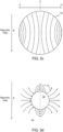
- Figure 3b shows the induced electrical current density 3c in a water droplet 3a traveling at a velocity under an imposed magnetic field B.
- the water droplet 3a is immersed in a non-conducting phase (gas or oil) multiphase flow 3b. Note that the denser lines represent increasing current density.
- Figure 3c illustrates the induced voltage created from the electrical current density in 3b.
- Figure 3d illustrates the electrical field distribution created from the electrical potential in figure 3c in the nonconducting fluid phase 3b. Again, the denser lines represent increasing electric field strength.
- Figure 3e illustrates the electrical field distribution E from multiple water droplets 3a traveling at a velocity in a non-conducting phase 3b.
- the electrical charge from these water droplets is capture by the electrode 2 and transfer to the low impedance circuit (charge amplifier) 2a.
- the electrode 2 in this embodiment is positioned in a direction perpendicular to the magnetic field and flow to optimize the measurements, and the measured capacitance will provide a measure of the flow velocity.
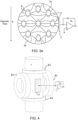
- Figure 4 illustrates a practical solution where the coils B1,B2 are positioned on opposite sides of the pipe 1. This may be combined with other measuring units, e.g. as disclosed above or in US 7,276,916 B2 where they use additional coils B3,B4 for measuring Water Volume Fraction. It can also be combined with the solution discussed in WO2020084132 / NO20181382 , using the same electrodes but possibly with additional measuring circuits connected to them.
- FIG 5 the output voltage from the charge measurement electronic 2a illustrated in figure 2b at different WVFs.
- the WVF1 is 40%
- WVF2 is 20%
- WVF3 is 10%
- WVF4 is 5%.
- the graph demonstrates the relationship of the charge with water velocity and the WVF, and as can been seen the accuracy of the measurements is increased with the WVF, but depending on the sensor circuitry the measurements are reliable at least down to 5% WVF and less.
- the present invention relates to a flow meter and corresponding method for measuring the flow velocity of water in a non-conductive oil continuous flow, preferably having a known WVF.
- the meter includes at least one magnetic field generator configured to provide a magnetic field with a known strength into said flow and also at least one sensor for measuring the charge at the sensor relative to a ground level or reference level, the sensor having low impedance circuitry.
- the sensor being positioned at a distance from the center of the magnetic field axis and the flow axis in essentially the same axial position as the magnetic field axis.
- the meter including calculating means for calculating a measure of the flow velocity based on the measured charge.
- the at least one sensor is positioned at a distance in the perpendicular direction from the axis of the flow as well as the magnetic field in order to maximize the sensitivity of the measurements.
- at least two sensors may be positioned on opposite sides of the pipe and magnetic field.
- Another embodiment may include a plurality of sensors distributed along the inner pipe surface, the sensors being connected to a measuring instrument for by analyzing the charge distribution determining the velocity distribution over the flow cross section.
- the magnetic field strength may be time varying magnetic field strength and the flow meter may then be configured to measure the response of the varying field on said at least one sensor.
- the at least one sensor is positioned in the pipe wall and may be electrically insulated from the flow or be in electric contact with the flow depending on the available sensor and application.
- the flow meter may also include a water volume fraction measuring instrument, measuring the water content of the flow, the calculation means being adapted to calculate the velocity also based on the determined water content or a storage device including predetermined information regarding the water content of the fluid flow, the calculation means being adapted to calculate the velocity also based on the determined water content.
- the calculation unit is calibrated based on a known flow conditions, measuring the velocity of the flow based on the measured deviations from the known flow conditions.
Landscapes
- Physics & Mathematics (AREA)
- General Physics & Mathematics (AREA)
- Chemical & Material Sciences (AREA)
- Life Sciences & Earth Sciences (AREA)
- Health & Medical Sciences (AREA)
- Fluid Mechanics (AREA)
- Engineering & Computer Science (AREA)
- General Health & Medical Sciences (AREA)
- Pathology (AREA)
- Immunology (AREA)
- Analytical Chemistry (AREA)
- Biochemistry (AREA)
- Chemical Kinetics & Catalysis (AREA)
- General Chemical & Material Sciences (AREA)
- Medicinal Chemistry (AREA)
- Food Science & Technology (AREA)
- Oil, Petroleum & Natural Gas (AREA)
- Electromagnetism (AREA)
- Electrochemistry (AREA)
- Measuring Volume Flow (AREA)
- Indicating Or Recording The Presence, Absence, Or Direction Of Movement (AREA)
Claims (13)
- Débitmètre permettant de mesurer la vitesse d'écoulement d'eau (3a) dans un écoulement multiphase continu d'huile non conducteur (3b) dans un tuyau (1), le débitmètre comprenant au moins un générateur de champ magnétique (B1, B2) conçu pour fournir un champ magnétique (B) ayant une intensité connue dans ledit écoulement, le débitmètre comprenant également au moins un capteur pour mesurer la charge au niveau du capteur par rapport à un niveau de sol, le capteur ayant un ensemble de circuits à basse impédance (2a) et étant positionné à une certaine distance du centre de l'axe de champ magnétique et de l'axe d'écoulement, dans sensiblement la même position axiale que l'axe de champ magnétique, dans lequel le débitmètre comprend également un moyen de calcul pour calculer une mesure de la vitesse d'écoulement sur la base de la charge mesurée.
- Débitmètre selon la revendication 1, dans lequel l'au moins un capteur est positionné à une certaine distance dans la direction perpendiculaire à partir de l'axe de l'écoulement ainsi que du champ magnétique.
- Débitmètre selon la revendication 1, comprenant au moins deux capteurs positionnés sur des côtés opposés du tuyau et du champ magnétique.
- Débitmètre selon la revendication 1, dans lequel le champ magnétique a une intensité de champ magnétique variable dans le temps, le débitmètre étant configuré pour mesurer la réponse du champ variable sur ledit au moins un capteur.
- Débitmètre selon la revendication 1, dans lequel l'au moins un capteur est positionné dans la paroi de tuyau étant isolée électriquement de l'écoulement.
- Débitmètre selon la revendication 1, dans lequel l'au moins un capteur est positionné dans la paroi de tuyau étant en contact électrique avec l'écoulement.
- Débitmètre selon la revendication 1, comprenant une pluralité de capteurs répartis le long de la surface de tuyau interne, les capteurs étant connectés à un instrument de mesure pour déterminer la répartition de vitesse d'eau sur la section transversale d'écoulement.
- Débitmètre selon la revendication 1, comprenant un instrument de mesure de fraction volumique d'eau, mesurant la teneur en eau de l'écoulement, le moyen de calcul étant conçu pour calculer la vitesse d'eau également sur la base de la teneur en eau déterminée.
- Débitmètre selon la revendication 1, comprenant un dispositif de stockage comprenant des informations prédéterminées comprenant la teneur en eau de l'écoulement de fluide, le moyen de calcul étant conçu pour calculer la vitesse d'eau également sur la base de la teneur en eau prédéterminée.
- Débitmètre selon la revendication 1, dans lequel l'unité de calcul est étalonnée sur la base de conditions d'écoulement connues, mesurant la vitesse de l'eau sur la base des écarts mesurés par rapport aux conditions d'écoulement connues.
- Procédé permettant de mesurer la vitesse d'écoulement d'eau (3a) dans un écoulement de fluide continu d'hydrocarbure non conducteur (3b) dans un tuyau (1), le procédé comprenant les étapes de :• application d'un champ magnétique (B) sur l'ensemble de l'écoulement de fluide• utilisation d'un capteur au niveau de la paroi de tuyau positionnée à l'extérieur de l'axe de champ magnétique mesurant la charge au niveau dudit capteur, le capteur ayant un ensemble de circuits à faible impédance (2a),• calcul de la vitesse d'écoulement d'eau sur la base de la charge mesurée au niveau dudit capteur.
- Procédé selon la revendication 11, dans lequel la vitesse d'écoulement d'eau est calculée sur la base de la charge mesurée et de la fraction volumique d'eau WVF de l'écoulement.
- Procédé selon la revendication 12, comprenant également l'étape de mesure de la WVF de l'écoulement avant le calcul.
Applications Claiming Priority (2)
| Application Number | Priority Date | Filing Date | Title |
|---|---|---|---|
| NO20200698A NO347033B1 (en) | 2020-06-12 | 2020-06-12 | Flow meter for measuring flow velocity in oil continuous flows |
| PCT/EP2021/065733 WO2021250225A1 (fr) | 2020-06-12 | 2021-06-11 | Débitmètre permettant de mesurer la vitesse d'écoulement dans des écoulements continus d'huile |
Publications (3)
| Publication Number | Publication Date |
|---|---|
| EP4165378A1 EP4165378A1 (fr) | 2023-04-19 |
| EP4165378B1 true EP4165378B1 (fr) | 2024-05-22 |
| EP4165378C0 EP4165378C0 (fr) | 2024-05-22 |
Family
ID=76553731
Family Applications (1)
| Application Number | Title | Priority Date | Filing Date |
|---|---|---|---|
| EP21733903.5A Active EP4165378B1 (fr) | 2020-06-12 | 2021-06-11 | Débitmètre permettant de mesurer la vitesse d'écoulement dans des écoulements continus d'huile |
Country Status (5)
| Country | Link |
|---|---|
| US (1) | US12372389B2 (fr) |
| EP (1) | EP4165378B1 (fr) |
| CN (1) | CN115698644B (fr) |
| NO (1) | NO347033B1 (fr) |
| WO (1) | WO2021250225A1 (fr) |
Families Citing this family (2)
| Publication number | Priority date | Publication date | Assignee | Title |
|---|---|---|---|---|
| GB2588201B (en) * | 2019-10-15 | 2024-08-14 | Flodatix Ltd | Apparatus for monitoring fluid flow in a pipe using electromagnetic velocity tomography |
| CN116840578B (zh) * | 2023-09-01 | 2023-11-21 | 中国海洋大学 | 一种水下电场动态测量流体噪声干扰抵消方法及装置 |
Family Cites Families (14)
| Publication number | Priority date | Publication date | Assignee | Title |
|---|---|---|---|---|
| GB2256490A (en) * | 1991-06-06 | 1992-12-09 | Schlumberger Ltd | Flow meter |
| JP3031096B2 (ja) * | 1993-01-29 | 2000-04-10 | 横河電機株式会社 | 容量式電磁流量計 |
| CN2427798Y (zh) * | 2000-04-19 | 2001-04-25 | 浙江大学 | 多电极流量检测信号处理器 |
| NO325535B1 (no) | 2002-09-10 | 2008-06-09 | Epsis As | Fremgangsmate og anordning til a bestemme vanninnhold i flerfaseblandinger |
| GB2403542B (en) * | 2003-06-30 | 2006-11-01 | Abb Ltd | Electromagnetic flow meter |
| US7503227B2 (en) * | 2005-07-13 | 2009-03-17 | Cidra Corporate Services, Inc | Method and apparatus for measuring parameters of a fluid flow using an array of sensors |
| GB201006409D0 (en) | 2010-04-17 | 2010-06-02 | Univ Huddersfield | Means and method for mearsuring the flow rate of fluid |
| US8429985B2 (en) * | 2010-08-24 | 2013-04-30 | General Electric Company | Apparatus for use in determining a plurality of characteristics of a multiphase flow within a pipe |
| GB2513679B (en) * | 2013-04-30 | 2016-01-06 | Iphase Ltd | Method of defining a mulitphase flow comprising three phases |
| FI127021B (fi) * | 2014-06-02 | 2017-09-29 | Senfit Oy | Anturi, mittalaite ja mittausmenetelmä |
| GB201416287D0 (en) * | 2014-09-15 | 2014-10-29 | Univ Leeds | Tomography apparatus, multi-phase flow monitoring system and corresponding methods |
| US11371868B2 (en) * | 2017-08-31 | 2022-06-28 | Micro Motion, Inc. | Conductive polymer reference connection for magnetic flowmeter |
| JP6940433B2 (ja) * | 2018-03-13 | 2021-09-29 | アズビル株式会社 | 容量式電磁流量計 |
| NO349684B1 (en) | 2018-10-26 | 2026-03-30 | Roxar Flow Measurement As | Flow measuring system |
-
2020
- 2020-06-12 NO NO20200698A patent/NO347033B1/en unknown
-
2021
- 2021-06-11 US US17/918,499 patent/US12372389B2/en active Active
- 2021-06-11 EP EP21733903.5A patent/EP4165378B1/fr active Active
- 2021-06-11 CN CN202180033796.9A patent/CN115698644B/zh active Active
- 2021-06-11 WO PCT/EP2021/065733 patent/WO2021250225A1/fr not_active Ceased
Also Published As
| Publication number | Publication date |
|---|---|
| CN115698644A (zh) | 2023-02-03 |
| NO20200698A1 (en) | 2021-12-13 |
| WO2021250225A1 (fr) | 2021-12-16 |
| EP4165378C0 (fr) | 2024-05-22 |
| CN115698644B (zh) | 2025-09-12 |
| US12372389B2 (en) | 2025-07-29 |
| US20230142240A1 (en) | 2023-05-11 |
| EP4165378A1 (fr) | 2023-04-19 |
| NO347033B1 (en) | 2023-04-24 |
Similar Documents
| Publication | Publication Date | Title |
|---|---|---|
| Andreussi et al. | An impedance method for the measurement of liquid hold-up in two-phase flow | |
| US5067345A (en) | Method and apparatus for measuring and calculating bulk water in crude oil or bulk water in steam | |
| US6467358B1 (en) | Method of measuring flow rates of respective fluids constituting multiphase fluid and flow meter for multiphase flow utilizing same | |
| Demori et al. | A capacitive sensor system for the analysis of two-phase flows of oil and conductive water | |
| EP0510774B1 (fr) | Méthode et dispositif pour mesurer des propriétés d'un écoulement multiphasique | |
| US9163967B2 (en) | Electromagnetic flow meter and method for monitoring fluid flow of a conducting fluid having either a uniform or a non-uniform flow profile | |
| US20150033830A1 (en) | Automated phase separation and fuel quality sensor | |
| EP3058356B1 (fr) | Système de détection en temps réel de dépôts ou d'inhibiteurs chimiques dans les environs de ou à la surface d'électrodes | |
| US9383330B2 (en) | Arrangement for determining the phase distribution in multiphase media having at least one highly conductive phase | |
| EP4030148B1 (fr) | Système et procédé pour fournir des mesures dans un tuyau | |
| US10197546B2 (en) | Method and system for continuous monitoring of the water fraction in an oil well stream | |
| US20140116117A1 (en) | Impedance method and arrangement for determining the composition of a multi-phase mixture | |
| Wang et al. | Development of a rotating electric field conductance sensor for measurement of water holdup in vertical oil–gas–water flows | |
| EP4165378B1 (fr) | Débitmètre permettant de mesurer la vitesse d'écoulement dans des écoulements continus d'huile | |
| Hai et al. | Differential C4D sensor for conductive and non-conductive fluidic channel | |
| US7946184B2 (en) | Electromagnetic flowmeter having temperature measurement value for correcting electrical conductivity value | |
| CA3127392C (fr) | Capteur de sonde compose d'enregistrement de production | |
| das Neves et al. | Development and dynamic characterisation of a conductance-based void meter array | |
| US10473502B2 (en) | Dielectric multiphase flow meter | |
| Lata et al. | Investigation of influence of area of electrodes on the characteristics of electrode polarization-based flow sensor | |
| Libert et al. | Capacitive Probe for Gas-Liquid Flow Characterization | |
| Vadde et al. | Theoretical and simulation analysis of the measurement of polarized fluid flow in a circular pipe with electric field excitation | |
| CN119936139A (zh) | 一种气液两相流体检测组件及其检测方法 | |
| Da Silva et al. | A NEW CAPACITANCE WIRE-MESH SENSOR FOR TWO-PHASE FLOW MEASUREMENT |
Legal Events
| Date | Code | Title | Description |
|---|---|---|---|
| STAA | Information on the status of an ep patent application or granted ep patent |
Free format text: STATUS: UNKNOWN |
|
| STAA | Information on the status of an ep patent application or granted ep patent |
Free format text: STATUS: THE INTERNATIONAL PUBLICATION HAS BEEN MADE |
|
| PUAI | Public reference made under article 153(3) epc to a published international application that has entered the european phase |
Free format text: ORIGINAL CODE: 0009012 |
|
| STAA | Information on the status of an ep patent application or granted ep patent |
Free format text: STATUS: REQUEST FOR EXAMINATION WAS MADE |
|
| 17P | Request for examination filed |
Effective date: 20221021 |
|
| AK | Designated contracting states |
Kind code of ref document: A1 Designated state(s): AL AT BE BG CH CY CZ DE DK EE ES FI FR GB GR HR HU IE IS IT LI LT LU LV MC MK MT NL NO PL PT RO RS SE SI SK SM TR |
|
| DAV | Request for validation of the european patent (deleted) | ||
| DAX | Request for extension of the european patent (deleted) | ||
| GRAP | Despatch of communication of intention to grant a patent |
Free format text: ORIGINAL CODE: EPIDOSNIGR1 |
|
| STAA | Information on the status of an ep patent application or granted ep patent |
Free format text: STATUS: GRANT OF PATENT IS INTENDED |
|
| INTG | Intention to grant announced |
Effective date: 20240123 |
|
| GRAS | Grant fee paid |
Free format text: ORIGINAL CODE: EPIDOSNIGR3 |
|
| GRAA | (expected) grant |
Free format text: ORIGINAL CODE: 0009210 |
|
| STAA | Information on the status of an ep patent application or granted ep patent |
Free format text: STATUS: THE PATENT HAS BEEN GRANTED |
|
| AK | Designated contracting states |
Kind code of ref document: B1 Designated state(s): AL AT BE BG CH CY CZ DE DK EE ES FI FR GB GR HR HU IE IS IT LI LT LU LV MC MK MT NL NO PL PT RO RS SE SI SK SM TR |
|
| REG | Reference to a national code |
Ref country code: GB Ref legal event code: FG4D |
|
| REG | Reference to a national code |
Ref country code: CH Ref legal event code: EP |
|
| REG | Reference to a national code |
Ref country code: DE Ref legal event code: R096 Ref document number: 602021013601 Country of ref document: DE |
|
| REG | Reference to a national code |
Ref country code: IE Ref legal event code: FG4D |
|
| U01 | Request for unitary effect filed |
Effective date: 20240605 |
|
| U07 | Unitary effect registered |
Designated state(s): AT BE BG DE DK EE FI FR IT LT LU LV MT NL PT SE SI Effective date: 20240620 |
|
| U20 | Renewal fee for the european patent with unitary effect paid |
Year of fee payment: 4 Effective date: 20240628 |
|
| PG25 | Lapsed in a contracting state [announced via postgrant information from national office to epo] |
Ref country code: IS Free format text: LAPSE BECAUSE OF FAILURE TO SUBMIT A TRANSLATION OF THE DESCRIPTION OR TO PAY THE FEE WITHIN THE PRESCRIBED TIME-LIMIT Effective date: 20240922 |
|
| PG25 | Lapsed in a contracting state [announced via postgrant information from national office to epo] |
Ref country code: HR Free format text: LAPSE BECAUSE OF FAILURE TO SUBMIT A TRANSLATION OF THE DESCRIPTION OR TO PAY THE FEE WITHIN THE PRESCRIBED TIME-LIMIT Effective date: 20240522 |
|
| PG25 | Lapsed in a contracting state [announced via postgrant information from national office to epo] |
Ref country code: GR Free format text: LAPSE BECAUSE OF FAILURE TO SUBMIT A TRANSLATION OF THE DESCRIPTION OR TO PAY THE FEE WITHIN THE PRESCRIBED TIME-LIMIT Effective date: 20240823 |
|
| PG25 | Lapsed in a contracting state [announced via postgrant information from national office to epo] |
Ref country code: ES Free format text: LAPSE BECAUSE OF FAILURE TO SUBMIT A TRANSLATION OF THE DESCRIPTION OR TO PAY THE FEE WITHIN THE PRESCRIBED TIME-LIMIT Effective date: 20240522 |
|
| PG25 | Lapsed in a contracting state [announced via postgrant information from national office to epo] |
Ref country code: PL Free format text: LAPSE BECAUSE OF FAILURE TO SUBMIT A TRANSLATION OF THE DESCRIPTION OR TO PAY THE FEE WITHIN THE PRESCRIBED TIME-LIMIT Effective date: 20240522 |
|
| PG25 | Lapsed in a contracting state [announced via postgrant information from national office to epo] |
Ref country code: PL Free format text: LAPSE BECAUSE OF FAILURE TO SUBMIT A TRANSLATION OF THE DESCRIPTION OR TO PAY THE FEE WITHIN THE PRESCRIBED TIME-LIMIT Effective date: 20240522 Ref country code: NO Free format text: LAPSE BECAUSE OF FAILURE TO SUBMIT A TRANSLATION OF THE DESCRIPTION OR TO PAY THE FEE WITHIN THE PRESCRIBED TIME-LIMIT Effective date: 20240822 Ref country code: IS Free format text: LAPSE BECAUSE OF FAILURE TO SUBMIT A TRANSLATION OF THE DESCRIPTION OR TO PAY THE FEE WITHIN THE PRESCRIBED TIME-LIMIT Effective date: 20240922 Ref country code: HR Free format text: LAPSE BECAUSE OF FAILURE TO SUBMIT A TRANSLATION OF THE DESCRIPTION OR TO PAY THE FEE WITHIN THE PRESCRIBED TIME-LIMIT Effective date: 20240522 Ref country code: GR Free format text: LAPSE BECAUSE OF FAILURE TO SUBMIT A TRANSLATION OF THE DESCRIPTION OR TO PAY THE FEE WITHIN THE PRESCRIBED TIME-LIMIT Effective date: 20240823 Ref country code: ES Free format text: LAPSE BECAUSE OF FAILURE TO SUBMIT A TRANSLATION OF THE DESCRIPTION OR TO PAY THE FEE WITHIN THE PRESCRIBED TIME-LIMIT Effective date: 20240522 Ref country code: RS Free format text: LAPSE BECAUSE OF FAILURE TO SUBMIT A TRANSLATION OF THE DESCRIPTION OR TO PAY THE FEE WITHIN THE PRESCRIBED TIME-LIMIT Effective date: 20240822 |
|
| PG25 | Lapsed in a contracting state [announced via postgrant information from national office to epo] |
Ref country code: CZ Free format text: LAPSE BECAUSE OF FAILURE TO SUBMIT A TRANSLATION OF THE DESCRIPTION OR TO PAY THE FEE WITHIN THE PRESCRIBED TIME-LIMIT Effective date: 20240522 |
|
| PG25 | Lapsed in a contracting state [announced via postgrant information from national office to epo] |
Ref country code: RO Free format text: LAPSE BECAUSE OF FAILURE TO SUBMIT A TRANSLATION OF THE DESCRIPTION OR TO PAY THE FEE WITHIN THE PRESCRIBED TIME-LIMIT Effective date: 20240522 Ref country code: SK Free format text: LAPSE BECAUSE OF FAILURE TO SUBMIT A TRANSLATION OF THE DESCRIPTION OR TO PAY THE FEE WITHIN THE PRESCRIBED TIME-LIMIT Effective date: 20240522 |
|
| PG25 | Lapsed in a contracting state [announced via postgrant information from national office to epo] |
Ref country code: SK Free format text: LAPSE BECAUSE OF FAILURE TO SUBMIT A TRANSLATION OF THE DESCRIPTION OR TO PAY THE FEE WITHIN THE PRESCRIBED TIME-LIMIT Effective date: 20240522 Ref country code: RO Free format text: LAPSE BECAUSE OF FAILURE TO SUBMIT A TRANSLATION OF THE DESCRIPTION OR TO PAY THE FEE WITHIN THE PRESCRIBED TIME-LIMIT Effective date: 20240522 Ref country code: CZ Free format text: LAPSE BECAUSE OF FAILURE TO SUBMIT A TRANSLATION OF THE DESCRIPTION OR TO PAY THE FEE WITHIN THE PRESCRIBED TIME-LIMIT Effective date: 20240522 |
|
| REG | Reference to a national code |
Ref country code: CH Ref legal event code: PL |
|
| PG25 | Lapsed in a contracting state [announced via postgrant information from national office to epo] |
Ref country code: MC Free format text: LAPSE BECAUSE OF FAILURE TO SUBMIT A TRANSLATION OF THE DESCRIPTION OR TO PAY THE FEE WITHIN THE PRESCRIBED TIME-LIMIT Effective date: 20240522 |
|
| REG | Reference to a national code |
Ref country code: DE Ref legal event code: R097 Ref document number: 602021013601 Country of ref document: DE |
|
| PLBE | No opposition filed within time limit |
Free format text: ORIGINAL CODE: 0009261 |
|
| STAA | Information on the status of an ep patent application or granted ep patent |
Free format text: STATUS: NO OPPOSITION FILED WITHIN TIME LIMIT |
|
| PG25 | Lapsed in a contracting state [announced via postgrant information from national office to epo] |
Ref country code: IE Free format text: LAPSE BECAUSE OF NON-PAYMENT OF DUE FEES Effective date: 20240611 |
|
| PG25 | Lapsed in a contracting state [announced via postgrant information from national office to epo] |
Ref country code: CH Free format text: LAPSE BECAUSE OF NON-PAYMENT OF DUE FEES Effective date: 20240630 |
|
| 26N | No opposition filed |
Effective date: 20250225 |
|
| U20 | Renewal fee for the european patent with unitary effect paid |
Year of fee payment: 5 Effective date: 20250520 |
|
| PGFP | Annual fee paid to national office [announced via postgrant information from national office to epo] |
Ref country code: GB Payment date: 20250520 Year of fee payment: 5 |
|
| PG25 | Lapsed in a contracting state [announced via postgrant information from national office to epo] |
Ref country code: SM Free format text: LAPSE BECAUSE OF FAILURE TO SUBMIT A TRANSLATION OF THE DESCRIPTION OR TO PAY THE FEE WITHIN THE PRESCRIBED TIME-LIMIT; INVALID AB INITIO Effective date: 20210611 |
|
| PG25 | Lapsed in a contracting state [announced via postgrant information from national office to epo] |
Ref country code: CY Free format text: LAPSE BECAUSE OF FAILURE TO SUBMIT A TRANSLATION OF THE DESCRIPTION OR TO PAY THE FEE WITHIN THE PRESCRIBED TIME-LIMIT; INVALID AB INITIO Effective date: 20210611 |
|
| PG25 | Lapsed in a contracting state [announced via postgrant information from national office to epo] |
Ref country code: HU Free format text: LAPSE BECAUSE OF FAILURE TO SUBMIT A TRANSLATION OF THE DESCRIPTION OR TO PAY THE FEE WITHIN THE PRESCRIBED TIME-LIMIT; INVALID AB INITIO Effective date: 20210611 |