EP4165663B1 - Dispositif de protection contre les rayonnements - Google Patents
Dispositif de protection contre les rayonnements Download PDFInfo
- Publication number
- EP4165663B1 EP4165663B1 EP21732043.1A EP21732043A EP4165663B1 EP 4165663 B1 EP4165663 B1 EP 4165663B1 EP 21732043 A EP21732043 A EP 21732043A EP 4165663 B1 EP4165663 B1 EP 4165663B1
- Authority
- EP
- European Patent Office
- Prior art keywords
- radiation
- sheet
- flaps
- lines
- radiation shield
- Prior art date
- Legal status (The legal status is an assumption and is not a legal conclusion. Google has not performed a legal analysis and makes no representation as to the accuracy of the status listed.)
- Active
Links
Images


Classifications
-
- G—PHYSICS
- G21—NUCLEAR PHYSICS; NUCLEAR ENGINEERING
- G21F—PROTECTION AGAINST X-RADIATION, GAMMA RADIATION, CORPUSCULAR RADIATION OR PARTICLE BOMBARDMENT; TREATING RADIOACTIVELY CONTAMINATED MATERIAL; DECONTAMINATION ARRANGEMENTS THEREFOR
- G21F3/00—Shielding characterised by its physical form, e.g. granules, or shape of the material
-
- A—HUMAN NECESSITIES
- A61—MEDICAL OR VETERINARY SCIENCE; HYGIENE
- A61B—DIAGNOSIS; SURGERY; IDENTIFICATION
- A61B6/00—Apparatus or devices for radiation diagnosis; Apparatus or devices for radiation diagnosis combined with radiation therapy equipment
- A61B6/10—Safety means specially adapted therefor
- A61B6/107—Protection against radiation, e.g. shielding
-
- G—PHYSICS
- G21—NUCLEAR PHYSICS; NUCLEAR ENGINEERING
- G21F—PROTECTION AGAINST X-RADIATION, GAMMA RADIATION, CORPUSCULAR RADIATION OR PARTICLE BOMBARDMENT; TREATING RADIOACTIVELY CONTAMINATED MATERIAL; DECONTAMINATION ARRANGEMENTS THEREFOR
- G21F1/00—Shielding characterised by the composition of the materials
- G21F1/02—Selection of uniform shielding materials
- G21F1/08—Metals; Alloys; Cermets, i.e. sintered mixtures of ceramics and metals
- G21F1/085—Heavy metals or alloys
-
- A—HUMAN NECESSITIES
- A61—MEDICAL OR VETERINARY SCIENCE; HYGIENE
- A61B—DIAGNOSIS; SURGERY; IDENTIFICATION
- A61B6/00—Apparatus or devices for radiation diagnosis; Apparatus or devices for radiation diagnosis combined with radiation therapy equipment
- A61B6/48—Diagnostic techniques
- A61B6/486—Diagnostic techniques involving generating temporal series of image data
- A61B6/487—Diagnostic techniques involving generating temporal series of image data involving fluoroscopy
-
- A—HUMAN NECESSITIES
- A61—MEDICAL OR VETERINARY SCIENCE; HYGIENE
- A61N—ELECTROTHERAPY; MAGNETOTHERAPY; RADIATION THERAPY; ULTRASOUND THERAPY
- A61N5/00—Radiation therapy
- A61N5/10—X-ray therapy; Gamma-ray therapy; Particle-irradiation therapy
- A61N2005/1092—Details
- A61N2005/1094—Shielding, protecting against radiation
Definitions
- the present invention relates to the protection against exposure to ionising radiation, more particularly to protective equipment in the field of radiation- and radiation-guided therapy, diagnosis and prognosis.
- Ionising radiations such as x-rays and gamma rays, are commonly used to diagnose, prognose and treat medical conditions. Examples of treatments using ionising radiation include radiation therapy for cancer patients, whereas fluoroscopy, x-ray imaging, CT scanning and nuclear imaging are routinely used in hospitals, medical and dental clinics, and in medical research to visualise the body's internal organs and structures.
- PPE Personal Protective Equipment
- Radiation protective clothing conventionally comprises heavy metals, usually lead, but because of the toxicity of lead and environmental concerns, these are being progressively replaced by lead-free materials and composites (with predetermined lead-equivalence values).
- Such protective clothing includes aprons, gloves, head and eye wear. Lead aprons are one of the key parts of personal radiation protection equipment along with lead gloves, lead glasses, and thyroid shields or collars.
- these PPE do not cover the whole body surface of the wearer, who consequently is exposed to direct and scattered radiation. This is particularly problematic in procedures where the health professionals must remain in close proximity to the radiation source. In these situations, lead protective clothing do not provide sufficient shielding against harmful radiation.
- a radiation shield device according to claim 1.
- the present invention is particularly advantageous in that it prevents radiation emanating from the radiation source from reaching the health professionals, and provides additional protection to the personal present in the treatment area.
- the shield device covers the patient but allows selective access to the target areas of the patient, whilst still shielding the health professional from radiation.
- the flaps are preferably arranged and configured to be moved individually from a "shielding configuration" (or “shield configuration”) in which it is in the plane of the sheet and covering the patient, to a “working configuration” in which it is folded over the sheet to expose the target area.
- the sheet comprises one or more pre-formed lines about which the flaps can be folded.
- the pre-formed lines enable the user to easily flip the flap open to uncover the target area, and to maintain the flap in the working configuration, in which the target area is exposed.
- the pre-formed lines may be located in or on a flap, in or on the sheet, or between a flap and the sheet, its primary (but not only) functions being to provide a guiding line for folding, and to stabilise the device over the patient.
- the rigidity of the sheet material is greater than the rigidity of the pre-formed lines.
- the pre-formed lines are more flexible than the material of the sheet, thereby forming a line of weakness about which the flap can be folded onto the sheet.
- a line of weakness is preferably an area of the sheet, wherein the thickness is smaller than the thickness of the remainder of the sheet.
- one or more of the pre-formed lines or folding lines may be devoid of sheet material.
- the pre-formed lines or folding lines may comprise or consist of one or more spines or battens as described in further detail hereinbelow. This configuration maintains the integrity of the sheet material and reduce or prevent tear and breakage.
- the rigidity of the pre-formed lines is greater than the rigidity of the sheet material.
- the pre-formed lines are more rigid than the material of the sheet, thereby acting as a spine about which the flap can be folded onto the sheet.
- the device according to the present invention may comprise one or more relatively rigid folding lines and/or one or more relatively flexible folding lines.
- the one or more pre-formed lines comprise a spine.
- the spine preferably comprises or consists of an elongated member about which the sheet and/or flap can be folded.
- the spine preferably comprises a member which is more rigid than the sheet material.
- the pre-formed line comprises a pocket configured and arranged so as to accommodate a spine.
- the pocket is preferably formed in or on the sheet material. It may be integrally formed in or on the sheet or secured to the sheet.
- the spine may be made of a rigid material. However, preferably, the spine is made of a bendable material. More preferably, the spine is made of a material which can be bent to confer a desired shape to said spine.
- the spine may be made of a flexible, bendable or shapable material, or a flexible, bendable or shapable structure, which enables the user to shape the spine, and therefore the sheet, as required during the procedure.
- the spine may comprise one section, or a plurality of sections. The latter configuration enables the flap to be folded completely or partially upon itself on upon the sheet.
- the spine preferably comprises an elongated member.
- the spine may have a circular, rectangular, triangular or other cross-sectional shape.
- the spine may be cylindrical, or made of a band of material.
- the device does not comprise any pre-formed lines. Instead, the device comprises one or more spines or battens about which the device may be folded.
- the weight of the shield may be adjusted depending on the intended use.
- a light sheet or blanket may be preferred for the comfort of the patient, but, if required, the weight of the shield may be increased to improve the stability of the shield on the patient. This may be effected by increasing the density of the sheet and/or of the spines.
- the shield may be a mat- or plate-like shield.
- the flaps are separated from adjacent sheet material and/or flap(s) along a separation line.
- the separation lines may be essentially lines along which the sheet material is cut so as to form the one or more flaps.
- the separation lines are preferably pre-cut, i.e. the flaps formed during the shield before the treatment or procedure, more preferably during the manufacturing process.
- the pre-formed flaps moot the need for cutting the shield to access target areas. Cutting the shield during use may lead to particle contamination and loss of sterility because of the non-sterile particles released from cutting and/or tearing the device. Nonetheless, it is envisaged within the scope of the invention to provide separation lines which may be easily detached, without contamination, to form the flap prior use, for example by providing means for separating the flap from the sheet or another flap along the separation line(s) prior to use.
- the separation lines are slits.
- the device may be seen as a sheet comprising a plurality of flaps, or as a sheet comprising a plurality of slits.
- the device further comprises means for covering the separation lines.
- the device may comprise covers to protect the separation lines.
- the covers may be integrally formed with the sheet material, or attached to the shield.
- a cover may be an elongated strip of material having a shape and dimensions to suitably cover a separation line.
- the barrier to ionising radiation comprises a material or component, which can absorb or block radiation.
- the barrier to ionising radiation comprises one or more heavy metals, such as lead.
- the barrier may comprise a composite material comprising lead, or a lead-free composite material which may include tin, antimony, tungsten, bismuth or other elements.
- the latter lead-free composite is advantageous in that they are safe for non-hazardous disposal and recycling.
- the barrier comprises one or more lead-free compounds with lead-equivalent properties.
- the device according to the present invention may comprise one or more additives, such as one or more antimicrobial layers, antibacterial agents, antifungal agents, antiyeast agents and/or antiviral agents.
- additives such as one or more antimicrobial layers, antibacterial agents, antifungal agents, antiyeast agents and/or antiviral agents.
- the device may comprise means for detecting ionising radiation. This feature is particularly advantageous to monitor radiation exposure in a direct and immediate manner during procedures and treatments.
- the device may comprise a compound or component capable of reacting upon exposure to ionizing radiation.
- the reaction may be to emit light, to emit a radiation at a different wavelength, or to change colour.
- Such compounds react in a detectable, visible and/or a measurable manner, thereby providing an indication of radiation exposure. This may be useful for monitoring the location and/or intensity of the radiation, and identifying areas e.g. where protection is required, or where radiation is insufficient for imaging or treatment.
- the device comprises a layer of material capable of reacting to radiation exposure. More preferably, the layer is positioned on the surface of the device facing away from the patient, i.e. facing the health professional, in use.
- This embodiment is particularly useful to detect any default, damage, breach and/or crack in the shield, which would leak radiation.
- the radiation is emitted from below the patient, travelled through the patient, and is absorbed or blocked by the shield. In the shield is damaged, radiation would reach the reactive material in the outer layer, thereby signalling a radiation leak to the user.
- the device may comprise or be coupled to a radiation sensor, such as a radiation dosimeter.
- the method may further comprise the step of forming folding lines in the sheet and/or the step of forming covers over the separation lines.
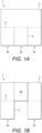
- a radiation shield device 1 comprising a sheet of material 2 comprising a plurality of flaps 3a, 3b, 3c, wherein said sheet 2 comprises a barrier to ionising radiation.
- the barrier absorbs and/or blocks ionising radiation, such as x-rays or gamma rays, used in treatment, diagnosis, prognosis and imaging processes.
- ionising radiation such as x-rays or gamma rays
- the present invention may be used in technological fields, other than the medical, dental and veterinary fields, wherein ionising radiations are used or encountered.
- the barrier may comprise one or more radiation blocking and/or absorbing agents.
- Preferred agents include heavy metals, such as lead, and other compounds and composite materials which are used in radiation PPE.
- the composite may be a heavy metal-containing composite or may be free of heavy metal, and instead may include one or more of tin, antimony, tungsten, bismuth or other radiation absorbing or blocking elements.
- the sheet 2 may be have a monolayer structure, wherein the layer comprises the barrier to ionising radiation. It may have a multilayer structure, wherein, in addition to the one or more radiation barrier layers, it includes other functional or aesthetic layers.
- the optional layers include structural layers, weighing layers, protective layers, surface layers such as cleanable layers, anti-slip layers, antimicrobial layers, antibacterial layers, antifungal layers, antiyeast layers, antiviral layers, mesh, fabric or textile layers, impermeable layers, and the like.
- the device may comprise coloured layers.
- the device comprises a leak detection layer
- the colour of the surface facing the patient is preferably different from the colour of the surface facing the health professional.
- the layers in a multilayer structure may be joined to each other by means of adhesive, co-extrusion, lamination, coating, mechanical attachment (such as sewing), and the like.
- the device 1 may be free of lead, so as to be easily disposed of and/or recyclable.
- the device 1 may be a single use device, and is sterilisable for repeated use.
- the shield device 1 is preferably substantially flexible so that it can rest on the body of the patient, substantially following his or her contours. Increasing the rigidity of the sheet (for example to form a plate) could facilitate the folding and unfolding of the flaps 3a, 3b, 3c, however, this would to be to the detriment of manoeuvrability for the health professional, and comfort for the patient.
- the device 1 comprises a plurality of flaps 3a, 3b, 3c.
- the sheet 1 and the flaps 3a, 3b, 3c are made of the same material and/or have the same structure. Although it is envisaged, within the scope of the present invention, that they may be made of different materials and/or have different structures.
- the device 1 comprises three flaps 3a, 3b, 3c, however, devices comprising more or fewer flaps are envisaged within the scope of the present invention.
- the dimensions, shape, location and number of flaps can be set depending on the intended procedure and target area(s).
- the flaps 3a, 3b, 3c extend from the sheet 2 and lie, in the shield configuration, in the plane of the sheet 2.
- the sheet 2 itself may form or may be used as a flap.
- a flap may be separated from an adjacent sheet and/or flap along one or more separation lines 4.
- the device may be provided with pre-detached separations lines 4. Additionally, or alternatively, the device may be provided with separation lines 4 which may allow the user to detach the flaps from adjacent flaps and/or sheets, prior use.
- the flap may be partially or completely detachable from the device.
- a flap may be connected to an adjacent sheet and/or flap by one or more folding lines 5.
- a folding line 5 is a line about which the sheet and/or flap can be folded.
- Figure 1A illustrates a shield device 1 in which the sheet 2 and flaps l are in a shielding configuration. The device 1 lies against the body of the patient, and the sheet 2 and flaps lie substantially in the same place.
- Figure 1B illustrate the same shield device 1, in which flaps 3a and 3c are in a shielding configuration, and flap 3b has been folded about the folding line 5 into a working configuration to expose a target area on the patient. In the shielding configuration, the flap 3b may lie flat against the sheet 2.
- the folding line 5 may enable a first flap to be folded upon a sheet or a second flap (i.e. if it is located between the first flap and the sheet or a second flap), or it may enable the first flap to be folded upon itself (i.e. if the folding line 5 is positioned across the flap).
- a folding line 5 may form one or more folding areas 6 between two or more folding lines ( figure 2 ), or may be a single line 5 ( figure 3 ).
- the folding area 6 may or may not be bordered by folding lines 5. In the latter case, the folding area 6 may be an area of different rigidity than that of the sheet 2 and/or flaps 3a, 3b, 3c. The folding area 6 may for example have a different thickness than the sheet and/or flaps, be made of a different material, and/or comprise one or more layers.
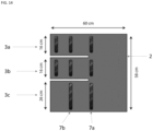
- the device 1 may comprise a pocket 8 to accommodate the spine 7, and the pocket 8 may be arranged and configured so that the spine 7 is embedded in the device 1 ( figure 4B ) or the pocket 8 may be formed substantially on the surface of the device 1 ( figure 4C ).
- the spine 7 may comprise or consist of metal, plastics materials, fabric, paper and/or cardboard. The spines or battens 7 facilitate the folding of a flap along a folding line 5, and prevent the folding of a flap onto itself.
- the one or more spines or battens 7 may be positioned across a sheet 2 or a flap 3a, 3b, 3c (i.e. transversally; e.g. by extending from on edge of the sheet or flap to an opposing or adjacent edge of the sheet or flap). Additionally or alternatively the one or more spines or battens 7 may be positioned at any one or more edges of the sheet 2 or flap(s) 3a, 3b, 3c.
- the device 1 comprises a peripheral hem 9 partially or completely along the periphery of the device 1, sheet 2 and/or flaps 3a, 3b, 3c (see figure 5 ).
- the hem 9 either has a higher density than the sheet material so as to weigh the device 1 onto the patient, and improve stability, or the peripheral hem 9 comprises a plurality of spines or battens.
- folding lines 5, folding areas 6, spines 7 and/or hem 9 described herein may be bendable or shapable. This enables the health professional to shape the device 1 to follow the anatomy of the patient, to facilitate access to specific target areas, to increase the protection efficiency of the device 1.
- Figures 6 and 7 illustrates a device 1 comprising a peripheral hem 9 incorporating a bendable spine 7, which allows the device 1 to be shaped as required.
- the outer flaps When placed over the patient, the outer flaps (e.g. 3a and 3c) have a tendency to slide outwardly towards the sides of the patient, thereby leaving gaps at the separation lines 4 between the flaps 3a, 3b, 3c, through which radiation can leak.
- the spines 7, and more generally the folding lines 5, and/or the hem 9 may act as battens to impart stability to the device 1, and to prevent the flaps 3a, 3c to slide outwardly.
- Other solutions are proposed to prevent the device 1 from shifting from its intended position, and the device 1 may be provided with means for improving the stability of the device.
- the device 1 (or bag 11) may be provided with an anti-slip surface, said surface facing, in use, the patient.
- the device 1 may be provided with attachment means, to attach the device 1 (or bag 11) to the patient's gown.
- spines 7 and/or hem 9 may be bendable or shapable so as to be bent or shaped to be secured to the patient.
- the spines 7 and/or hem 9 may be made of a material which is heavier than the material of the sheet 1 and/or flaps, so as a weigh the device 1 down onto the patient.
- the device 1, as a whole may be thick or heavy enough to weigh down onto the patient.
- the spines or battens 7 may comprise or consist of a magnetic material or element, to prevent two adjacent spines or battens 7 from accidentally pulling apart from each other.
- batten 7a creates a folding line about which a flap 3a, 3b, 3c may be folded about, for example to rest upon the sheet 2.
- battens 7b are positioned transversally across the flap(s) 3a, 3b, 3c to create multiple folding lines about which the flaps can be folded, for example upon itself.
- each flap can be selectively, and completely or partially, lifted for the medical practitioner to reveal the area to be visualised.
- the flaps 3a,3b,3c provide protection when lying on the patient, and access when the patient is uncovered.
- the separation lines 4, i.e. the slit between two flaps 3a,3b,3c or between a sheet 2 and a flap3a,3b,3c, themselves may be used to access target areas.
- the flaps may be separated so as to allow access through the slit, whilst still protecting the health professional from harmful radiation.
- Examples of procedures which may require imaging include surgery (e.g. cardiac, vascular, gastrointestinal, pulmonary, thoracic, neurological, orthopaedical, urological, gynaecological), catheter insertion which requires a visualisation of the circulatory system) and device implantation (e.g. ventricular assist devices, stents and pacemakers).
- surgery e.g. cardiac, vascular, gastrointestinal, pulmonary, thoracic, neurological, orthopaedical, urological, gynaecological
- catheter insertion which requires a visualisation of the circulatory system
- device implantation e.g. ventricular assist devices, stents and pacemakers.
- the radiation emitted by the radiation-emitting device X can now pass through the patient, and reach the image-processing device P so that the surgeon can visualise the groin area and more particularly the femoral artery and veins. Once the catheter is inserted, its path can be visualised by selectively lifting the flaps and/or sheet. If the access point is found to be unsuitable, then the surgeon may decide to close the flap, and attempt insertion from a different access point on the patient.
- Real life registry data were used on radiation doses from different planes over a year as a template for dosimetry experiments with a human x-ray model. Real time dosimetry was with and without the device were performed during fluoroscopy. By comparing the given radiation with received dose in this setting we found that the device provides protection in a real-life model by 93% over a year. Furthermore, the mat was most effective in settings where operator exposure is highest.
- the present invention enables optimum protection against radiation, whilst providing the versatility required in medical procedure.
- the shield is versatile and enables health professionals to perform procedures without the concern of exposure.
- the radiation shield device according to the present invention is a useful addition to the currently available radiation PPE.
Landscapes
- Engineering & Computer Science (AREA)
- Life Sciences & Earth Sciences (AREA)
- Health & Medical Sciences (AREA)
- Physics & Mathematics (AREA)
- Medical Informatics (AREA)
- High Energy & Nuclear Physics (AREA)
- Metallurgy (AREA)
- Pathology (AREA)
- Public Health (AREA)
- General Engineering & Computer Science (AREA)
- Nuclear Medicine, Radiotherapy & Molecular Imaging (AREA)
- Optics & Photonics (AREA)
- Veterinary Medicine (AREA)
- Radiology & Medical Imaging (AREA)
- Biomedical Technology (AREA)
- Heart & Thoracic Surgery (AREA)
- Molecular Biology (AREA)
- Surgery (AREA)
- Animal Behavior & Ethology (AREA)
- General Health & Medical Sciences (AREA)
- Biophysics (AREA)
- Ceramic Engineering (AREA)
- Apparatus For Radiation Diagnosis (AREA)
- Radiation-Therapy Devices (AREA)
Claims (16)
- Dispositif (1) de protection contre les rayonnements pour l'imagerie, la thérapie, le diagnostic ou le pronostic, par rayonnements et guidés par rayonnements, d'un sujet, dans lequel ledit dispositif de protection contre les rayonnements est stérilisable ;dans lequel ledit dispositif de protection contre les rayonnements comprend une feuille (2) de matériau comprenant une pluralité de rabats (3a, 3b, 3c) configurés pour être pliables de façon à exposer sélectivement une zone cible du sujet,dans lequel ladite feuille (2) comprend une barrière aux rayonnements ionisants ;caractérisé en ce que le dispositif comprend un bord périphérique (9) partiellement ou complètement le long de la périphérie du dispositif (1), de la feuille (2) et/ou des rabats (3a, 3b, 3c), dans lequel le bord (9) présente une masse volumique supérieure à celle du matériau de la feuille ; ou une pluralité d'épines ou de lattes.
- Dispositif selon la revendication 1, dans lequel le dispositif comprend une couche externe stérilisable ou consiste en un matériau stérilisable.
- Dispositif selon la revendication 1 ou la revendication 2, dans lequel la feuille comprend une ou plusieurs lignes préformées (5) autour desquelles les rabats peuvent être pliés.
- Dispositif selon la revendication 3, dans lequel la rigidité du matériau de la feuille est plus grande que la rigidité des lignes préformées.
- Dispositif selon la revendication 3, dans lequel la rigidité des lignes préformées est plus grande que la rigidité du matériau de la feuille.
- Dispositif selon la revendication 3, dans lequel les une ou plusieurs lignes préformées comprennent une épine (7) ;
facultativement, dans lequel l'épine est constituée d'un matériau pliable. - Dispositif selon une quelconque revendication précédente, dans lequel les rabats sont séparés du matériau de feuille adjacent et/ou du (des) rabat(s) le long d'une ligne de séparation ;
facultativement, dans lequel le dispositif comprend en outre un moyen pour couvrir les lignes de séparation. - Dispositif selon une quelconque revendication précédente, dans lequel la barrière aux rayonnements ionisants comprend un ou plusieurs métaux lourds.
- Dispositif selon une quelconque revendication précédente, dans lequel le dispositif comprend un(e) ou plusieurs couches antimicrobiennes, agents antimicrobiens, agents antifongiques, agents anti-levure et/ou agents antiviraux, ou des combinaisons de ceux-ci.
- Dispositif selon une quelconque revendication précédente, dans lequel le dispositif comprend en outre un moyen pour détecter des rayonnements ionisants.
- Dispositif selon la revendication 10, dans lequel le dispositif comprend un composé ou un composant capable d'émettre de la lumière lors de l'exposition à des rayonnements ionisants.
- Système pour l'imagerie, la thérapie, le diagnostic ou le pronostic, par rayonnements et guidés par rayonnements, d'un sujet comprenant un dispositif (1) de protection contre les rayonnements selon une quelconque revendication précédente et une poche (11) stérilisée ou stérilisable configurée pour recevoir le dispositif de protection contre les rayonnements dans celle-ci.
- Système selon la revendication 12, dans lequel la poche présente sensiblement la même forme externe que le dispositif de protection contre les rayonnements, et dans lequel les dimensions externes de la poche sont plus grandes que celles du dispositif de protection contre les rayonnements.
- Système selon la revendication 12 ou la revendication 13, dans lequel le dispositif de protection contre les rayonnements comprend une ou plusieurs épines ou lattes (7).
- Procédé de fabrication d'un dispositif (1) de protection contre les rayonnements selon l'une quelconque des revendications 1 à 11, comprenant les étapes de :fourniture d'une feuille (2) de matériau comprenant une barrière aux rayonnements ionisants ; etdécoupe de la feuille le long d'une ou plusieurs lignes de séparation (4) pour former des rabats.
- Procédé selon la revendication 15,comprenant en outre l'étape de formation de lignes de pliage (5) dans la feuille ; et/oucomprenant en outre l'étape de formation d'éléments de couverture (10) sur les lignes de séparation.
Applications Claiming Priority (2)
| Application Number | Priority Date | Filing Date | Title |
|---|---|---|---|
| GBGB2008931.4A GB202008931D0 (en) | 2020-06-12 | 2020-06-12 | Radiation shield device |
| PCT/EP2021/065834 WO2021250255A1 (fr) | 2020-06-12 | 2021-06-11 | Dispositif de protection contre les rayonnements |
Publications (3)
| Publication Number | Publication Date |
|---|---|
| EP4165663A1 EP4165663A1 (fr) | 2023-04-19 |
| EP4165663B1 true EP4165663B1 (fr) | 2024-11-27 |
| EP4165663C0 EP4165663C0 (fr) | 2024-11-27 |
Family
ID=71835579
Family Applications (1)
| Application Number | Title | Priority Date | Filing Date |
|---|---|---|---|
| EP21732043.1A Active EP4165663B1 (fr) | 2020-06-12 | 2021-06-11 | Dispositif de protection contre les rayonnements |
Country Status (5)
| Country | Link |
|---|---|
| US (1) | US20230138584A1 (fr) |
| EP (1) | EP4165663B1 (fr) |
| CN (1) | CN115812239A (fr) |
| GB (1) | GB202008931D0 (fr) |
| WO (1) | WO2021250255A1 (fr) |
Families Citing this family (1)
| Publication number | Priority date | Publication date | Assignee | Title |
|---|---|---|---|---|
| SE548211C2 (en) | 2022-02-25 | 2026-04-21 | Texray Ab | Radiation protection shielding system |
Citations (2)
| Publication number | Priority date | Publication date | Assignee | Title |
|---|---|---|---|---|
| DE19619297A1 (de) * | 1995-08-24 | 1997-02-27 | Siemens Ag | Strahlenschutzvorrichtung mit zumindest einem Strahlenschutzlappen |
| WO2005104942A2 (fr) * | 2004-04-22 | 2005-11-10 | Ansel Gary M | Dispositif a utiliser lors d'actes medicaux |
Family Cites Families (4)
| Publication number | Priority date | Publication date | Assignee | Title |
|---|---|---|---|---|
| US7057194B2 (en) * | 2004-04-07 | 2006-06-06 | Eco Cath-Lab Systems, Inc. | Radiation barrier |
| JP2015537196A (ja) * | 2012-10-02 | 2015-12-24 | アナロジック コーポレイション | 放射線システム用エネルギーシールド{energyshieldforradiationsystem} |
| US10032532B2 (en) * | 2015-12-22 | 2018-07-24 | Globe Composite Solutions, Ltd. | Shielding curtain assembly for an electromagnetic radiation scanning system |
| US10688316B2 (en) * | 2018-06-11 | 2020-06-23 | Butsonian Enterprises Pty Ltd | Medical shield |
-
2020
- 2020-06-12 GB GBGB2008931.4A patent/GB202008931D0/en not_active Ceased
-
2021
- 2021-06-11 EP EP21732043.1A patent/EP4165663B1/fr active Active
- 2021-06-11 CN CN202180041516.9A patent/CN115812239A/zh active Pending
- 2021-06-11 WO PCT/EP2021/065834 patent/WO2021250255A1/fr not_active Ceased
-
2022
- 2022-12-12 US US18/064,850 patent/US20230138584A1/en active Pending
Patent Citations (2)
| Publication number | Priority date | Publication date | Assignee | Title |
|---|---|---|---|---|
| DE19619297A1 (de) * | 1995-08-24 | 1997-02-27 | Siemens Ag | Strahlenschutzvorrichtung mit zumindest einem Strahlenschutzlappen |
| WO2005104942A2 (fr) * | 2004-04-22 | 2005-11-10 | Ansel Gary M | Dispositif a utiliser lors d'actes medicaux |
Also Published As
| Publication number | Publication date |
|---|---|
| CN115812239A (zh) | 2023-03-17 |
| US20230138584A1 (en) | 2023-05-04 |
| EP4165663C0 (fr) | 2024-11-27 |
| WO2021250255A1 (fr) | 2021-12-16 |
| GB202008931D0 (en) | 2020-07-29 |
| EP4165663A1 (fr) | 2023-04-19 |
Similar Documents
| Publication | Publication Date | Title |
|---|---|---|
| EP2645936B1 (fr) | Ensemble de protection contre les rayonnements et procédé de réalisation d'une barrière stérile contre les rayonnements | |
| US7591590B2 (en) | Radiation attenuation system | |
| KR101515834B1 (ko) | 방사선 방호물질로 만들어진 윈드 스크린용 살균 커버 | |
| EP2084713B1 (fr) | Dispositif de protection d'opérateur de fluoroscopie | |
| US9224508B2 (en) | Radiation resistant medical gown | |
| US4938233A (en) | Radiation shield | |
| US7099427B2 (en) | Radiation attenuation system | |
| US7663128B2 (en) | Radiation shield securing and covering system | |
| US6674087B2 (en) | Radiation attenuation system | |
| US4670658A (en) | Protective sheet | |
| US20160317110A1 (en) | Radiation Shield Assembly and Method of Providing a Sterile Barrier to Radiation | |
| US5015865A (en) | X-ray-protective surgical garment having a removable lead insert | |
| US10692616B2 (en) | Radiation attenuating protective garments | |
| US20200051705A1 (en) | Neck support with radiation protection | |
| US20140299796A1 (en) | Particle radiation shielding head cover | |
| US20140299795A1 (en) | Shielded head cover with varying attenuation portions | |
| WO2012138565A2 (fr) | Ecrans atténuant une irradiation à usage limité, doublures pour écrans atténuant une irradiation et procédés | |
| US20230138584A1 (en) | Radiation shield device | |
| US20150124941A1 (en) | C-arm sleeve | |
| US20230380526A1 (en) | Surgical utility gown | |
| JP2023100587A (ja) | 被ばくと防護負荷を低減する複合化した防護機器・器具 | |
| SE2250265A1 (en) | Radiation protection shielding system | |
| CN105869690A (zh) | 一种血管造影时使用的防辐射帘 | |
| WO2023153345A1 (fr) | Dispositif/instrument de protection permettant de réduire l'exposition au rayonnement et la charge de protection |
Legal Events
| Date | Code | Title | Description |
|---|---|---|---|
| STAA | Information on the status of an ep patent application or granted ep patent |
Free format text: STATUS: UNKNOWN |
|
| STAA | Information on the status of an ep patent application or granted ep patent |
Free format text: STATUS: THE INTERNATIONAL PUBLICATION HAS BEEN MADE |
|
| PUAI | Public reference made under article 153(3) epc to a published international application that has entered the european phase |
Free format text: ORIGINAL CODE: 0009012 |
|
| STAA | Information on the status of an ep patent application or granted ep patent |
Free format text: STATUS: REQUEST FOR EXAMINATION WAS MADE |
|
| 17P | Request for examination filed |
Effective date: 20221104 |
|
| AK | Designated contracting states |
Kind code of ref document: A1 Designated state(s): AL AT BE BG CH CY CZ DE DK EE ES FI FR GB GR HR HU IE IS IT LI LT LU LV MC MK MT NL NO PL PT RO RS SE SI SK SM TR |
|
| DAV | Request for validation of the european patent (deleted) | ||
| DAX | Request for extension of the european patent (deleted) | ||
| STAA | Information on the status of an ep patent application or granted ep patent |
Free format text: STATUS: EXAMINATION IS IN PROGRESS |
|
| 17Q | First examination report despatched |
Effective date: 20230929 |
|
| GRAP | Despatch of communication of intention to grant a patent |
Free format text: ORIGINAL CODE: EPIDOSNIGR1 |
|
| STAA | Information on the status of an ep patent application or granted ep patent |
Free format text: STATUS: GRANT OF PATENT IS INTENDED |
|
| RAP3 | Party data changed (applicant data changed or rights of an application transferred) |
Owner name: VESTLANDETS INNOVASJONS SELSKAP AS (VIS) |
|
| INTG | Intention to grant announced |
Effective date: 20240701 |
|
| GRAS | Grant fee paid |
Free format text: ORIGINAL CODE: EPIDOSNIGR3 |
|
| GRAA | (expected) grant |
Free format text: ORIGINAL CODE: 0009210 |
|
| STAA | Information on the status of an ep patent application or granted ep patent |
Free format text: STATUS: THE PATENT HAS BEEN GRANTED |
|
| AK | Designated contracting states |
Kind code of ref document: B1 Designated state(s): AL AT BE BG CH CY CZ DE DK EE ES FI FR GB GR HR HU IE IS IT LI LT LU LV MC MK MT NL NO PL PT RO RS SE SI SK SM TR |
|
| REG | Reference to a national code |
Ref country code: GB Ref legal event code: FG4D |
|
| RIN1 | Information on inventor provided before grant (corrected) |
Inventor name: DAVIDSEN, CEDRIC Inventor name: TUSETH, VEGARD |
|
| REG | Reference to a national code |
Ref country code: CH Ref legal event code: EP |
|
| REG | Reference to a national code |
Ref country code: IE Ref legal event code: FG4D |
|
| REG | Reference to a national code |
Ref country code: DE Ref legal event code: R096 Ref document number: 602021022452 Country of ref document: DE |
|
| U01 | Request for unitary effect filed |
Effective date: 20241219 |
|
| U07 | Unitary effect registered |
Designated state(s): AT BE BG DE DK EE FI FR IT LT LU LV MT NL PT RO SE SI Effective date: 20250114 |
|
| PG25 | Lapsed in a contracting state [announced via postgrant information from national office to epo] |
Ref country code: IS Free format text: LAPSE BECAUSE OF FAILURE TO SUBMIT A TRANSLATION OF THE DESCRIPTION OR TO PAY THE FEE WITHIN THE PRESCRIBED TIME-LIMIT Effective date: 20250327 Ref country code: HR Free format text: LAPSE BECAUSE OF FAILURE TO SUBMIT A TRANSLATION OF THE DESCRIPTION OR TO PAY THE FEE WITHIN THE PRESCRIBED TIME-LIMIT Effective date: 20241127 |
|
| PG25 | Lapsed in a contracting state [announced via postgrant information from national office to epo] |
Ref country code: ES Free format text: LAPSE BECAUSE OF FAILURE TO SUBMIT A TRANSLATION OF THE DESCRIPTION OR TO PAY THE FEE WITHIN THE PRESCRIBED TIME-LIMIT Effective date: 20241127 |
|
| PG25 | Lapsed in a contracting state [announced via postgrant information from national office to epo] |
Ref country code: GR Free format text: LAPSE BECAUSE OF FAILURE TO SUBMIT A TRANSLATION OF THE DESCRIPTION OR TO PAY THE FEE WITHIN THE PRESCRIBED TIME-LIMIT Effective date: 20250228 |
|
| PG25 | Lapsed in a contracting state [announced via postgrant information from national office to epo] |
Ref country code: PL Free format text: LAPSE BECAUSE OF FAILURE TO SUBMIT A TRANSLATION OF THE DESCRIPTION OR TO PAY THE FEE WITHIN THE PRESCRIBED TIME-LIMIT Effective date: 20241127 |
|
| PG25 | Lapsed in a contracting state [announced via postgrant information from national office to epo] |
Ref country code: RS Free format text: LAPSE BECAUSE OF FAILURE TO SUBMIT A TRANSLATION OF THE DESCRIPTION OR TO PAY THE FEE WITHIN THE PRESCRIBED TIME-LIMIT Effective date: 20250227 |
|
| PG25 | Lapsed in a contracting state [announced via postgrant information from national office to epo] |
Ref country code: SM Free format text: LAPSE BECAUSE OF FAILURE TO SUBMIT A TRANSLATION OF THE DESCRIPTION OR TO PAY THE FEE WITHIN THE PRESCRIBED TIME-LIMIT Effective date: 20241127 |
|
| PGFP | Annual fee paid to national office [announced via postgrant information from national office to epo] |
Ref country code: GB Payment date: 20250617 Year of fee payment: 5 |
|
| PGFP | Annual fee paid to national office [announced via postgrant information from national office to epo] |
Ref country code: NO Payment date: 20250624 Year of fee payment: 5 |
|
| PG25 | Lapsed in a contracting state [announced via postgrant information from national office to epo] |
Ref country code: SK Free format text: LAPSE BECAUSE OF FAILURE TO SUBMIT A TRANSLATION OF THE DESCRIPTION OR TO PAY THE FEE WITHIN THE PRESCRIBED TIME-LIMIT Effective date: 20241127 |
|
| PG25 | Lapsed in a contracting state [announced via postgrant information from national office to epo] |
Ref country code: CZ Free format text: LAPSE BECAUSE OF FAILURE TO SUBMIT A TRANSLATION OF THE DESCRIPTION OR TO PAY THE FEE WITHIN THE PRESCRIBED TIME-LIMIT Effective date: 20241127 |
|
| PGFP | Annual fee paid to national office [announced via postgrant information from national office to epo] |
Ref country code: IE Payment date: 20250623 Year of fee payment: 5 |
|
| U20 | Renewal fee for the european patent with unitary effect paid |
Year of fee payment: 5 Effective date: 20250620 |
|
| PLBE | No opposition filed within time limit |
Free format text: ORIGINAL CODE: 0009261 |
|
| STAA | Information on the status of an ep patent application or granted ep patent |
Free format text: STATUS: NO OPPOSITION FILED WITHIN TIME LIMIT |
|
| REG | Reference to a national code |
Ref country code: CH Ref legal event code: L10 Free format text: ST27 STATUS EVENT CODE: U-0-0-L10-L00 (AS PROVIDED BY THE NATIONAL OFFICE) Effective date: 20251008 |
|
| 26N | No opposition filed |
Effective date: 20250828 |
|
| REG | Reference to a national code |
Ref country code: CH Ref legal event code: H13 Free format text: ST27 STATUS EVENT CODE: U-0-0-H10-H13 (AS PROVIDED BY THE NATIONAL OFFICE) Effective date: 20260127 |
|
| PG25 | Lapsed in a contracting state [announced via postgrant information from national office to epo] |
Ref country code: MC Free format text: LAPSE BECAUSE OF FAILURE TO SUBMIT A TRANSLATION OF THE DESCRIPTION OR TO PAY THE FEE WITHIN THE PRESCRIBED TIME-LIMIT Effective date: 20241127 |
|
| REG | Reference to a national code |
Ref country code: GB Ref legal event code: 732E Free format text: REGISTERED BETWEEN 20260108 AND 20260114 |
|
| U1K | Transfer of rights of the unitary patent after the registration of the unitary effect |
Owner name: TEXRAY AB; SE |
|
| U1N | Appointed representative for the unitary patent procedure changed after the registration of the unitary effect |
Representative=s name: OEBERG & SJOEBERG AB; SE |
|
| PG25 | Lapsed in a contracting state [announced via postgrant information from national office to epo] |
Ref country code: CH Free format text: LAPSE BECAUSE OF NON-PAYMENT OF DUE FEES Effective date: 20250630 |