EP4165706B1 - Pile individuelle et empilement de piles à combustible ayant des structures élastiques pour distribuer uniformément des milieux de travail - Google Patents
Pile individuelle et empilement de piles à combustible ayant des structures élastiques pour distribuer uniformément des milieux de travail Download PDFInfo
- Publication number
- EP4165706B1 EP4165706B1 EP21799249.4A EP21799249A EP4165706B1 EP 4165706 B1 EP4165706 B1 EP 4165706B1 EP 21799249 A EP21799249 A EP 21799249A EP 4165706 B1 EP4165706 B1 EP 4165706B1
- Authority
- EP
- European Patent Office
- Prior art keywords
- section
- media
- media port
- flow cross
- fuel cell
- Prior art date
- Legal status (The legal status is an assumption and is not a legal conclusion. Google has not performed a legal analysis and makes no representation as to the accuracy of the status listed.)
- Active
Links
Images


Classifications
-
- H—ELECTRICITY
- H01—ELECTRIC ELEMENTS
- H01M—PROCESSES OR MEANS, e.g. BATTERIES, FOR THE DIRECT CONVERSION OF CHEMICAL ENERGY INTO ELECTRICAL ENERGY
- H01M8/00—Fuel cells; Manufacture thereof
- H01M8/02—Details
- H01M8/0271—Sealing or supporting means around electrodes, matrices or membranes
- H01M8/0273—Sealing or supporting means around electrodes, matrices or membranes with sealing or supporting means in the form of a frame
-
- H—ELECTRICITY
- H01—ELECTRIC ELEMENTS
- H01M—PROCESSES OR MEANS, e.g. BATTERIES, FOR THE DIRECT CONVERSION OF CHEMICAL ENERGY INTO ELECTRICAL ENERGY
- H01M8/00—Fuel cells; Manufacture thereof
- H01M8/10—Fuel cells with solid electrolytes
- H01M8/1004—Fuel cells with solid electrolytes characterised by membrane-electrode assemblies [MEA]
-
- H—ELECTRICITY
- H01—ELECTRIC ELEMENTS
- H01M—PROCESSES OR MEANS, e.g. BATTERIES, FOR THE DIRECT CONVERSION OF CHEMICAL ENERGY INTO ELECTRICAL ENERGY
- H01M8/00—Fuel cells; Manufacture thereof
- H01M8/24—Grouping of fuel cells, e.g. stacking of fuel cells
- H01M8/241—Grouping of fuel cells, e.g. stacking of fuel cells with solid or matrix-supported electrolytes
- H01M8/242—Grouping of fuel cells, e.g. stacking of fuel cells with solid or matrix-supported electrolytes comprising framed electrodes or intermediary frame-like gaskets
-
- H—ELECTRICITY
- H01—ELECTRIC ELEMENTS
- H01M—PROCESSES OR MEANS, e.g. BATTERIES, FOR THE DIRECT CONVERSION OF CHEMICAL ENERGY INTO ELECTRICAL ENERGY
- H01M8/00—Fuel cells; Manufacture thereof
- H01M8/24—Grouping of fuel cells, e.g. stacking of fuel cells
- H01M8/2457—Grouping of fuel cells, e.g. stacking of fuel cells with both reactants being gaseous or vaporised
-
- H—ELECTRICITY
- H01—ELECTRIC ELEMENTS
- H01M—PROCESSES OR MEANS, e.g. BATTERIES, FOR THE DIRECT CONVERSION OF CHEMICAL ENERGY INTO ELECTRICAL ENERGY
- H01M8/00—Fuel cells; Manufacture thereof
- H01M8/24—Grouping of fuel cells, e.g. stacking of fuel cells
- H01M8/2465—Details of groupings of fuel cells
- H01M8/2483—Details of groupings of fuel cells characterised by internal manifolds
-
- H—ELECTRICITY
- H01—ELECTRIC ELEMENTS
- H01M—PROCESSES OR MEANS, e.g. BATTERIES, FOR THE DIRECT CONVERSION OF CHEMICAL ENERGY INTO ELECTRICAL ENERGY
- H01M8/00—Fuel cells; Manufacture thereof
- H01M8/10—Fuel cells with solid electrolytes
- H01M2008/1095—Fuel cells with polymeric electrolytes
-
- Y—GENERAL TAGGING OF NEW TECHNOLOGICAL DEVELOPMENTS; GENERAL TAGGING OF CROSS-SECTIONAL TECHNOLOGIES SPANNING OVER SEVERAL SECTIONS OF THE IPC; TECHNICAL SUBJECTS COVERED BY FORMER USPC CROSS-REFERENCE ART COLLECTIONS [XRACs] AND DIGESTS
- Y02—TECHNOLOGIES OR APPLICATIONS FOR MITIGATION OR ADAPTATION AGAINST CLIMATE CHANGE
- Y02E—REDUCTION OF GREENHOUSE GAS [GHG] EMISSIONS, RELATED TO ENERGY GENERATION, TRANSMISSION OR DISTRIBUTION
- Y02E60/00—Enabling technologies; Technologies with a potential or indirect contribution to GHG emissions mitigation
- Y02E60/30—Hydrogen technology
- Y02E60/50—Fuel cells
Definitions
- the invention relates to a single cell for a fuel cell stack of a fuel cell device.
- a membrane electrode arrangement is arranged, to which at least one single plate, but preferably a bipolar plate made up of two interconnected single plates, is assigned.
- the single plate is formed with a flow field for supplying an operating medium into the active region of the membrane electrode arrangement, which in turn is fluidically connected to a media port located away from the active region.
- a large number of media ports stacked on top of one another and aligned with one another form a main channel for the operating media, in particular the cathode gas, the fuel or the coolant.
- the invention further relates to a fuel cell stack with a plurality of individual cells stacked on top of one another.
- Fuel cell devices are used for the chemical conversion of a fuel with oxygen to water in order to generate electrical energy.
- fuel cells contain the so-called membrane electrode assembly (MEA) as a core component, which is a composite of a proton-conducting membrane and an electrode (anode and cathode) arranged on both sides of the membrane.
- MEA membrane electrode assembly
- GDL gas diffusion layers
- the fuel cell device is operated with a plurality of fuel cells combined to form a fuel cell stack the fuel, in particular hydrogen H 2 or a hydrogen-containing gas mixture, is fed to the anode, where an electrochemical oxidation of H 2 to H + takes place with the release of electrons.
- the protons H + are transported from the anode chamber to the cathode chamber via the electrolyte or the membrane, which separates the reaction chambers from one another in a gas-tight manner and electrically insulates them.
- the electrons provided at the anode are fed to the cathode via an electrical line.
- Oxygen or an oxygen-containing gas mixture is fed to the cathode, so that a reduction of O 2 to O 2- takes place with the absorption of electrons.
- these oxygen anions react with the protons transported across the membrane to form water.
- the reactant gases are fed to the electrodes of the fuel cells via bipolar plates.
- a cooling medium is also passed through the bipolar plates due to the heat generated during the fuel cell reaction, so that three different media are passed through the bipolar plates in a very small space.
- main channels ports
- seals are used to seal the main channels lengthways through the fuel cell stack. In addition, there must be a good seal against the cooling medium flowing in the coolant channels.
- the EN 10 2017 202 705 A1 , the EN 10 2014 220 682 A1 and the EN 10 2017 211 755 A1 the use of insert or plug-in elements in the main channels, which change the usable flow cross-section over the length of the respective main channel. In this way, a uniform pressure and thus Achieve flow distribution of the operating media.
- the bipolar plates can be formed with the same dimensions, so that the number of identical parts is increased, which leads to a reduction in costs.
- the media ports of the bipolar plates with different flow cross-sections, whereby, for example, the flow cross-section of the main outlet channels is chosen to be larger than the flow cross-section of the main inlet channels.
- the larger cross-section on the outlet side slows down the flow speed and increases the pressure in the outlet, which affects the even distribution. Due to the resulting asymmetry of the individual cells, a lot of installation space is required for the fuel cell stack formed in this way, whereby the bracing of the individual cells to the fuel cell stack is also subject to an asymmetrical force distribution that must be balanced out.
- JP 2014 002920 A describes a fuel cell stack with an exhaust gas collection channel into which slats extend, partially covering the flow cross-section of the channel. The slats are used to control the water.
- US 2011/165492 A1 describes a fuel cell stack in which a wedge is inserted into a fluid distribution channel to reduce the cross-section of the channel along the flow direction and thereby compensate for the fluid loss in the flow direction.
- EP 3 336 949 A1 describes a fuel cell stack in which an insert element is inserted into an air distribution channel.
- the insert element has openings through which the air reaches the individual fuel cells. These openings have different cross-sections in order to adapt the amount of air specifically to the individual fuel cells.
- the bipolar plate according to the invention is characterized in particular by the fact that laterally with respect to the membrane electrode arrangement there is a lamella that at least partially covers the flow cross-section of the media port and is designed to be elastically bendable or elastically flexible in order to change the usable flow cross-section of the media port by the force of a reaction medium flowing axially through the media port.
- the even distribution is optimized by means of a plurality of bending or folding lamellae along the relevant main channel, which is created by the aligned stacked arrangement of the media ports of the individual cells.
- the lamella which adjusts the usable flow cross-section of the media port. It is therefore advantageous if the lamella is adjustable depending on the force of the flowing operating medium acting on it between a folded-over configuration in which there is an enlarged usable flow cross-section of the media port and a deflection-free configuration in which there is a reduced usable flow cross-section of the media port compared to the enlarged usable flow cross-section.
- the membrane electrode arrangement of the individual cell is enclosed in an insulating layer and if the lamella forms part of this insulating layer.
- the insulating layer is a membrane-electrode arrangement surrounding frame and/or a sealing layer surrounding the membrane electrode arrangement (e.g. so-called “sub-gasket” or RIM).
- a sealing layer surrounding the membrane electrode arrangement (e.g. so-called "sub-gasket” or RIM).
- the lamella can be formed in a simple manner if at least one slot that is open on one side is introduced into the part of the insulating layer that protrudes into the usable flow cross-section of the media port. With only a single open slot, for example, two half-lamellas protruding into the media port can be created.
- two slots running parallel to one another and open on one side are introduced into the part of the insulating layer that protrudes into the usable flow cross-section of the media port, because in this way a "folding over" of the slats is promoted by the force of the flowing operating medium.
- the lamella includes a concave section that extends into the usable flow cross-section of the media port.
- the formation of a convex section that extends into the flow cross-section is also possible.
- the use of other geometries that promote even distribution across the stack is also possible.
- the flow field of the single plate or the bipolar plate is fluidically connected to the inlet-side media port and fluidically to an outlet-side media port, and if the inlet-side and outlet-side media ports are formed with the same dimensions.
- highly symmetrical single cells can be produced, in which preferably a majority, in particular all of the existing lamellae are formed with the same dimensions. are.
- the slats of the individual cells can be dimensioned in such a way that the slat of a first individual cell is supported by the slat of the individual cell stacked adjacent to the first individual cell when it is folded over due to force.
- the slats support each other, with the slats becoming increasingly more stacked as the distance from the media connection in the flow direction of the operating medium increases.
- This stacking of the slats increasingly narrows the flow cross-section, which has a positive effect on the even distribution.
- this type of configuration allows additional lateral sealing to be achieved through the overlapping slats.
- the fuel cell stack 1 shown consists of a plurality of fuel cells 2 connected in series.
- Each of the fuel cells 2 comprises an anode and a cathode as well as a proton-conductive membrane separating the anode from the cathode.
- the two electrodes together with the membrane form a membrane electrode assembly 7 (MEA for short).
- the membrane is made of an ionomer, preferably a sulfonated tetrafluoroethylene polymer (PTFE) or a polymer of perfluorinated sulfonic acid (PFSA).
- PTFE sulfonated tetrafluoroethylene polymer
- PFSA perfluorinated sulfonic acid
- the membrane can be formed as a sulfonated hydrocarbon membrane.
- Fuel for example hydrogen is supplied to the anodes via anode spaces within the fuel cell stack 1.
- Fuel or fuel molecules are split into protons and electrons at the anode.
- the membrane allows the protons (for example H + ) to pass through, but is impermeable to the electrons (e-).
- the following reaction takes place at the anode: 2H 2 ⁇ 4H + + 4e - (oxidation/electron release). While the protons pass through the membrane to the cathode, the electrons are conducted to the cathode or to an energy storage device via an external circuit.
- Cathode gas for example oxygen or oxygen-containing air
- Cathode gas can be supplied to the cathodes via cathode spaces within the fuel cell stack 1, so that the following reaction takes place on the cathode side: O 2 + 4H + + 4e - ⁇ 2H 2 O (reduction/electron absorption).
- Compressed air is supplied to the fuel cell stack 1 via a cathode fresh gas line by a compressor.
- the fuel cell stack 1 is connected to a cathode exhaust gas line.
- hydrogen held in a hydrogen tank is supplied to the fuel cell stack 1 via an anode fresh gas line to provide the reactants required for the electrochemical reaction in a fuel cell 2.
- These gases are transferred to bipolar plates 3, which have main channels from media ports 4 for the distribution of the gases to the membrane and for the discharge.
- the bipolar plates have main coolant channels from media ports 5 for the passage of a coolant in a coolant channel 6, so that three different media are guided in the smallest space.
- the main channels 4, 5 of a plurality of fuel cells 2 with bipolar plates 3 forming the fuel cell stack 1 are also shown, each grouped in pairs.
- the membrane electrode arrangement 7, together with the associated bipolar plate 3, forms a single cell of the fuel cell stack 1.
- FIG. 2 A detailed section of the fuel cell stack 1 along section II-II from Figure 1 is in Figure 2 This section runs through the active Region 13 of the fuel cell stack 1.
- the active region 13 of the bipolar plate 3 is of course not electrochemically active itself, but it is arranged adjacent to those constituents of the fuel cell 2 in which the electrochemical fuel cell reaction takes place, namely on or via the membrane electrode arrangement 7. It can be seen that the bipolar plate 3 in this active region 13 has the reactant flow fields on its surfaces facing away from one another, which are arranged opposite one another and thus form an opposite configuration.
- the reactant flow fields each have a plurality of flow channels 9 for the respective reaction medium, delimited by walls 11 of webs 10.
- the webs 10 and the flow channels 9 of one of the individual plates 8 are thus designed to run opposite the webs 10 and the flow channels 9 of the other of the individual plates 8 in this active region 13. In this way, coolant channels 6 of a coolant flow field extending between the individual plates 8 are formed.
- a distribution area 14 with a distribution field comprising channels between the media ports 4, 5 forming the main channels and the active area 13.
- the channels have suitable branches for guiding the operating media. Downstream of the active area 3, i.e. downstream of the respective flow field, the partial media flows are collected again in a collection area 18 and discharged via the outlet-side media port 4, 5.
- the media ports 4, 5 - at least those on the inlet side - provide for the use of at least one lamella 12. This is arranged laterally or to the side with respect to the membrane electrode arrangement 7 and at least partially covers the usable flow cross-section of the media port 4, 5.
- the lamella 12 is elastically bendable or formed elastically yielding.
- FIG. 3 The detailed views of the media port 4 of the fuel cell stack 1 shown at the top left from Figure 1 is the Figures 3 to 6
- the membrane electrode arrangement 7 is enclosed in an insulating layer, in this case in a frame 16, with the lamella 12 forming part of the frame 16. It could also be part of a sealing structure ("sub-gasket" / RIM).
- Two slots 15 running parallel to one another and open on one side are made in the frame in the part that protrudes into the usable flow cross-section of the media port 4, 5.
- These two slots 15 form the lamella 12, which can be elastically bent into or out of the paper plane, in particular folded over. It can be seen that the lamella 12 is provided with a concave section 17 that protrudes into the usable flow cross-section of the media port 4, 5 and serves to produce the desired flow resistance. A different shape to produce a different desired flow resistance is also possible.
- FIG 6 a design of the slats 12 is shown, which - as in the design according to Figure 3 shown - by two lateral slots 15 and by - as in the design according to Figure 4 shown - are formed by a central slot 15.
- concave sections 17 are located on the two lamellae 12 before.
- the proportion of coverage by the lamella 12 to the lamella-free, cut-out media port 4, 5 can be specifically varied and adjusted in order to optimize the uniform distribution for the respective fuel cell stack 1.
- the dimensions and shape of the lamellas 12 are specifically adapted to the material thickness of the insulating and mechanical properties of the frame (frame of the MEA).
- the slats 12 are adjustable, depending on the force of the flowing operating medium acting on them, between a folded-over configuration in which there is an enlarged usable flow cross-section of the media port 4, 5, and a deflection-free configuration in which there is a reduced usable flow cross-section of the media port 4, 5 compared to the enlarged usable flow cross-section.
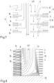
- the sectional view after Figure 8 shows that the lamellae 12 of the individual cells are dimensioned in such a way that the lamellae 12 of a first individual cell is supported by the lamellae 12 of the individual cell stacked adjacent to the first individual cell in the event of a force-induced folding.
- the lamellae 12 support each other, with an increasing accumulation of the lamellae 12 as the distance from the media connection in the flow direction of the operating medium increases. Due to this accumulation of the lamellae 12, the usable flow cross-section of the main channel is increasingly narrowed, which ensures the even distribution of the flowing operating medium.
- such a configuration can provide additional lateral sealing through the overlapping lamellae 12.
- the lamellae 12 have identical dimensions in the present case. A specific dimension for the lamellae 12 that can be changed across the stack is also conceivable.
- the present invention provides an even distribution of the media flows already in the main channel, so that there is an improved media distribution over the entire bipolar plate 3, over the entire individual cell and thus over the entire fuel cell stack 1.
Landscapes
- Life Sciences & Earth Sciences (AREA)
- Engineering & Computer Science (AREA)
- Manufacturing & Machinery (AREA)
- Sustainable Development (AREA)
- Sustainable Energy (AREA)
- Chemical & Material Sciences (AREA)
- Chemical Kinetics & Catalysis (AREA)
- Electrochemistry (AREA)
- General Chemical & Material Sciences (AREA)
- Fuel Cell (AREA)
Claims (10)
- Pile individuelle pour un empilement de piles à combustible (1), avec un agencement membrane-électrodes (7) disposé dans une zone active (13), auquel au moins une plaque individuelle (8) est associée, qui est formée avec un champ d'écoulement pour l'apport d'un fluide de fonctionnement dans la zone active (13) de l'agencement membrane-électrodes (7), qui est connecté par mécanique des fluides à un orifice de fluide (4, 5) présent à l'écart de la zone active (13), caractérisée en ce qu'une lamelle (12) est présente latéralement par rapport à l'agencement membrane-électrodes (7), recouvrant au moins partiellement la section transversale d'écoulement de l'orifice de fluide (4, 5), qui est formée élastiquement de manière pliable pour modifier la section transversale d'écoulement utile de l'orifice de fluide (4, 5) par la force d'un fluide de réaction s'écoulant axialement à travers l'orifice de fluide (4, 5).
- Pile individuelle selon la revendication 1, caractérisée en ce que la lamelle (12) peut être déplacée en fonction de la force exercée sur elle par le fluide de fonctionnement s'écoulant entre une configuration rabattue, dans laquelle une section transversale d'écoulement utile agrandie de l'orifice de fluide (4, 5) est présente, et une configuration sans déviation, dans laquelle une section transversale d'écoulement utile de l'orifice de fluide (4, 5) réduite par rapport à la section transversale d'écoulement utile agrandie est présente.
- Pile individuelle selon la revendication 1 ou 2, caractérisée en ce que l'agencement membrane-électrodes (7) est entouré d'une couche isolante, et en ce que la lamelle (12) forme une partie de la couche isolante.
- Pile individuelle selon la revendication 3, caractérisée en ce que la couche isolante est un cadre (16) entourant l'agencement membrane-électrodes (7) et/ou une couche d'étanchéité entourant l'agencement membrane-électrodes (7).
- Pile individuelle selon la revendication 3 ou 4, caractérisée en ce que, pour former la lamelle (12), au moins une fente (15) ouverte d'un côté est pratiquée dans la partie de la couche isolante qui fait saillie dans la section transversale d'écoulement utile de l'orifice de fluide (4, 5).
- Pile individuelle selon la revendication 5, caractérisée en ce que deux fentes (15) ouvertes d'un côté et parallèles entre elles sont pratiquées dans la partie de la couche isolante qui fait saillie dans la section transversale d'écoulement utile de l'orifice de fluide (4, 5).
- Pile individuelle selon l'une quelconque des revendications 1 à 6, caractérisée en ce que la lamelle (12) comprend une section concave (17) qui fait saillie dans la section transversale d'écoulement utile de l'orifice de fluide (4, 5).
- Pile individuelle selon l'une quelconque des revendications 1 à 7, caractérisée en ce que le champ d'écoulement est connecté par mécanique des fluides à des orifices de fluide côté entrée (4, 5) et par mécanique des fluides à un orifice de fluide côté sortie (4, 5), dans laquelle les orifices de fluide côté entrée et côté sortie (4, 5) sont formés avec les mêmes dimensions.
- Empilement de piles à combustible (1) comprenant une pluralité de piles individuelles selon l'une quelconque des revendications 1 à 8, dans lequel les orifices de fluide (4, 5) sont orientés les uns aux autres.
- Empilement de piles à combustible (1) selon la revendication 9, caractérisé en ce que les lamelles (12) des piles individuelles sont dimensionnées de sorte que la lamelle (12) d'une première pile individuelle s'appuie, lors d'un rabattement induit par une force, sur la lamelle (12) de la pile individuelle empilée à proximité de la première pile individuelle.
Applications Claiming Priority (2)
| Application Number | Priority Date | Filing Date | Title |
|---|---|---|---|
| DE102020128559.0A DE102020128559A1 (de) | 2020-10-30 | 2020-10-30 | Einzelzelle und Brennstoffzellenstapel mit elastischen Strukturen zur Gleichverteilung von Betriebsmedien |
| PCT/EP2021/079487 WO2022090128A1 (fr) | 2020-10-30 | 2021-10-25 | Pile individuelle et empilement de piles à combustible ayant des structures élastiques pour distribuer uniformément des milieux de travail |
Publications (2)
| Publication Number | Publication Date |
|---|---|
| EP4165706A1 EP4165706A1 (fr) | 2023-04-19 |
| EP4165706B1 true EP4165706B1 (fr) | 2024-09-18 |
Family
ID=78414657
Family Applications (1)
| Application Number | Title | Priority Date | Filing Date |
|---|---|---|---|
| EP21799249.4A Active EP4165706B1 (fr) | 2020-10-30 | 2021-10-25 | Pile individuelle et empilement de piles à combustible ayant des structures élastiques pour distribuer uniformément des milieux de travail |
Country Status (5)
| Country | Link |
|---|---|
| US (1) | US12463232B2 (fr) |
| EP (1) | EP4165706B1 (fr) |
| CN (1) | CN115885399B (fr) |
| DE (1) | DE102020128559A1 (fr) |
| WO (1) | WO2022090128A1 (fr) |
Families Citing this family (1)
| Publication number | Priority date | Publication date | Assignee | Title |
|---|---|---|---|---|
| DE202023103258U1 (de) * | 2023-06-13 | 2024-09-17 | Reinz-Dichtungs-Gmbh | Separatorplatte für ein elektrochemisches System |
Family Cites Families (12)
| Publication number | Priority date | Publication date | Assignee | Title |
|---|---|---|---|---|
| IL173539A0 (en) * | 2006-02-05 | 2006-07-05 | Rami Noach | Flow distributor plate |
| JP5083313B2 (ja) | 2007-04-20 | 2012-11-28 | トヨタ自動車株式会社 | 燃料電池のセパレータおよび燃料電池 |
| US8835070B2 (en) | 2010-05-11 | 2014-09-16 | Ford Motor Company | Fuel cell header wedge |
| JP2014002920A (ja) | 2012-06-19 | 2014-01-09 | Panasonic Corp | 燃料電池 |
| CN103746123B (zh) * | 2014-02-18 | 2016-08-31 | 武汉理工大学 | 质子交换膜燃料电池金属双极板及其构成的电堆 |
| DE102014220682A1 (de) | 2014-10-13 | 2016-04-14 | Robert Bosch Gmbh | Medienverteilung in Brennstoffzellenstacks |
| DE102015218757B4 (de) * | 2015-09-29 | 2025-06-12 | Audi Ag | Brennstoffzellenstapel und Brennstoffzellensystem |
| DE202016105311U1 (de) * | 2016-09-23 | 2018-01-09 | Reinz-Dichtungs-Gmbh | Strömungsplatte für einen Befeuchter |
| US10547064B2 (en) * | 2016-10-05 | 2020-01-28 | GM Global Technology Operations LLC | Tunnel cross section for more uniformed contact pressure distribution on metal bead seal at the intersection between bead and tunnel |
| DE102016225444A1 (de) | 2016-12-19 | 2018-06-21 | Robert Bosch Gmbh | Verbesserte Medienverteilung in Brennstoffzellenstacks |
| DE102017202705A1 (de) | 2017-02-20 | 2018-08-23 | Bayerische Motoren Werke Aktiengesellschaft | Brennstoffzellenstapel mit Verteilungselement im Medienkanal sowie Herstellverfahren |
| DE102017211755A1 (de) | 2017-07-10 | 2019-01-10 | Audi Ag | Einsteckelement für einen Header eines Brennstoffzellenstapels |
-
2020
- 2020-10-30 DE DE102020128559.0A patent/DE102020128559A1/de active Pending
-
2021
- 2021-10-25 EP EP21799249.4A patent/EP4165706B1/fr active Active
- 2021-10-25 CN CN202180047103.1A patent/CN115885399B/zh active Active
- 2021-10-25 US US18/003,136 patent/US12463232B2/en active Active
- 2021-10-25 WO PCT/EP2021/079487 patent/WO2022090128A1/fr not_active Ceased
Also Published As
| Publication number | Publication date |
|---|---|
| CN115885399B (zh) | 2025-10-21 |
| US20230261239A1 (en) | 2023-08-17 |
| US12463232B2 (en) | 2025-11-04 |
| CN115885399A (zh) | 2023-03-31 |
| DE102020128559A1 (de) | 2022-05-05 |
| EP4165706A1 (fr) | 2023-04-19 |
| WO2022090128A1 (fr) | 2022-05-05 |
Similar Documents
| Publication | Publication Date | Title |
|---|---|---|
| DE69514364T2 (de) | Stapel elektrochemischer brennstoffzellen mit gleichzeitig fliessenden kuehlmittel- und oxidantienstroemen | |
| WO2017186770A1 (fr) | Plaque bipolaire comportant des canaux à gaz réactif présentant des surfaces de section transversale variables, empilement de pile à combustible et véhicule équipé d'un tel empilement de pile à combustible | |
| DE102015225228A1 (de) | Bipolarplatte für eine Brennstoffzelle sowie Brennstoffzellenstapel mit einer solchen | |
| DE102016202010A1 (de) | Bipolarplatte mit asymmetrischen Dichtungsabschnitten, sowie Brennstoffzellenstapel mit einer solchen | |
| EP4022701B1 (fr) | Plaque bipolaire | |
| WO2017025555A1 (fr) | Plaque bipolaire ainsi qu'empilement de piles à combustible muni d'une plaque bipolaire de ce type | |
| WO2017220552A1 (fr) | Plaque bipolaire à largeur variable des canaux à gaz de réaction dans la zone d'entrée de la zone active, empilement de cellules à combustible et système de cellules à combustible comportant de telles plaques bipolaires et véhicule | |
| EP4154335B1 (fr) | Plaque bipolaire et empilement de piles à combustible | |
| DE102006019114A1 (de) | Brennstoffzellenbetriebsverfahren zur verbesserten Wasserstoff- und Sauerstoffverwendung | |
| DE10243163A1 (de) | Brennstoffzellenpaket | |
| DE102015218757B4 (de) | Brennstoffzellenstapel und Brennstoffzellensystem | |
| DE102015223640A1 (de) | Brennstoffzellenstapel | |
| WO2022090128A1 (fr) | Pile individuelle et empilement de piles à combustible ayant des structures élastiques pour distribuer uniformément des milieux de travail | |
| EP4150687B1 (fr) | Plaque bipolaire et empilement de piles à combustible | |
| WO2017085030A1 (fr) | Empilement de piles à combustible, comprenant des plaques bipolaires, et système de piles à combustible | |
| EP4197045B1 (fr) | Plaque bipolaire comprenant des ramifications de canaux et empilement des piles à combustible | |
| EP4165705B1 (fr) | Plaque bipolaire et empilement de piles à combustible | |
| DE102015223930A1 (de) | Bipolarplatte sowie Brennstoffzelle | |
| EP4165703B1 (fr) | Plaque bipolaire avec obturateur insérable et empilement de cellules élémentaires | |
| DE102018211078B3 (de) | Bipolarplatte für Brennstoffzellen mit drei Einzelplatten, sowie Brennstoffzelle und Brennstoffzellenstapel mit solchen Bipolarplatten | |
| DE102021119655B4 (de) | Membranelektrodenanordnung, Brennstoffzellenstapel, Brennstoffzellenvorrichtung und Kraftfahrzeug mit einer solchen | |
| DE102012011441A1 (de) | Membran-Elektroden-Einheit für eine Brennstoffzelle | |
| DE102015122264A1 (de) | Bipolarplatte für Brennstoffzellen mit optimiertem Design, Brennstoffzellenstapel mit solchen Bipolarplatten sowie Fahrzeug mit einem solchen Brennstoffzellenstapel | |
| DE102020133764A1 (de) | Bipolarplatte mit verschachtelt angeordneten Medienports der Reaktanten und Brennstoffzellenstapel | |
| DE102020128583A1 (de) | Brennstoffzellenstapel und Bipolarplatte mit Medienregulierung |
Legal Events
| Date | Code | Title | Description |
|---|---|---|---|
| STAA | Information on the status of an ep patent application or granted ep patent |
Free format text: STATUS: UNKNOWN |
|
| STAA | Information on the status of an ep patent application or granted ep patent |
Free format text: STATUS: THE INTERNATIONAL PUBLICATION HAS BEEN MADE |
|
| PUAI | Public reference made under article 153(3) epc to a published international application that has entered the european phase |
Free format text: ORIGINAL CODE: 0009012 |
|
| STAA | Information on the status of an ep patent application or granted ep patent |
Free format text: STATUS: REQUEST FOR EXAMINATION WAS MADE |
|
| 17P | Request for examination filed |
Effective date: 20230111 |
|
| AK | Designated contracting states |
Kind code of ref document: A1 Designated state(s): AL AT BE BG CH CY CZ DE DK EE ES FI FR GB GR HR HU IE IS IT LI LT LU LV MC MK MT NL NO PL PT RO RS SE SI SK SM TR |
|
| P01 | Opt-out of the competence of the unified patent court (upc) registered |
Effective date: 20230529 |
|
| DAV | Request for validation of the european patent (deleted) | ||
| DAX | Request for extension of the european patent (deleted) | ||
| GRAP | Despatch of communication of intention to grant a patent |
Free format text: ORIGINAL CODE: EPIDOSNIGR1 |
|
| STAA | Information on the status of an ep patent application or granted ep patent |
Free format text: STATUS: GRANT OF PATENT IS INTENDED |
|
| INTG | Intention to grant announced |
Effective date: 20240524 |
|
| GRAS | Grant fee paid |
Free format text: ORIGINAL CODE: EPIDOSNIGR3 |
|
| GRAA | (expected) grant |
Free format text: ORIGINAL CODE: 0009210 |
|
| STAA | Information on the status of an ep patent application or granted ep patent |
Free format text: STATUS: THE PATENT HAS BEEN GRANTED |
|
| AK | Designated contracting states |
Kind code of ref document: B1 Designated state(s): AL AT BE BG CH CY CZ DE DK EE ES FI FR GB GR HR HU IE IS IT LI LT LU LV MC MK MT NL NO PL PT RO RS SE SI SK SM TR |
|
| REG | Reference to a national code |
Ref country code: GB Ref legal event code: FG4D Free format text: NOT ENGLISH |
|
| REG | Reference to a national code |
Ref country code: CH Ref legal event code: EP |
|
| REG | Reference to a national code |
Ref country code: DE Ref legal event code: R096 Ref document number: 502021005208 Country of ref document: DE |
|
| REG | Reference to a national code |
Ref country code: IE Ref legal event code: FG4D Free format text: LANGUAGE OF EP DOCUMENT: GERMAN |
|
| REG | Reference to a national code |
Ref country code: LT Ref legal event code: MG9D |
|
| PG25 | Lapsed in a contracting state [announced via postgrant information from national office to epo] |
Ref country code: NO Free format text: LAPSE BECAUSE OF FAILURE TO SUBMIT A TRANSLATION OF THE DESCRIPTION OR TO PAY THE FEE WITHIN THE PRESCRIBED TIME-LIMIT Effective date: 20241218 |
|
| PG25 | Lapsed in a contracting state [announced via postgrant information from national office to epo] |
Ref country code: GR Free format text: LAPSE BECAUSE OF FAILURE TO SUBMIT A TRANSLATION OF THE DESCRIPTION OR TO PAY THE FEE WITHIN THE PRESCRIBED TIME-LIMIT Effective date: 20241219 Ref country code: FI Free format text: LAPSE BECAUSE OF FAILURE TO SUBMIT A TRANSLATION OF THE DESCRIPTION OR TO PAY THE FEE WITHIN THE PRESCRIBED TIME-LIMIT Effective date: 20240918 |
|
| PG25 | Lapsed in a contracting state [announced via postgrant information from national office to epo] |
Ref country code: BG Free format text: LAPSE BECAUSE OF FAILURE TO SUBMIT A TRANSLATION OF THE DESCRIPTION OR TO PAY THE FEE WITHIN THE PRESCRIBED TIME-LIMIT Effective date: 20240918 |
|
| PG25 | Lapsed in a contracting state [announced via postgrant information from national office to epo] |
Ref country code: LV Free format text: LAPSE BECAUSE OF FAILURE TO SUBMIT A TRANSLATION OF THE DESCRIPTION OR TO PAY THE FEE WITHIN THE PRESCRIBED TIME-LIMIT Effective date: 20240918 |
|
| PG25 | Lapsed in a contracting state [announced via postgrant information from national office to epo] |
Ref country code: HR Free format text: LAPSE BECAUSE OF FAILURE TO SUBMIT A TRANSLATION OF THE DESCRIPTION OR TO PAY THE FEE WITHIN THE PRESCRIBED TIME-LIMIT Effective date: 20240918 |
|
| REG | Reference to a national code |
Ref country code: NL Ref legal event code: MP Effective date: 20240918 |
|
| PG25 | Lapsed in a contracting state [announced via postgrant information from national office to epo] |
Ref country code: RS Free format text: LAPSE BECAUSE OF FAILURE TO SUBMIT A TRANSLATION OF THE DESCRIPTION OR TO PAY THE FEE WITHIN THE PRESCRIBED TIME-LIMIT Effective date: 20241218 |
|
| PG25 | Lapsed in a contracting state [announced via postgrant information from national office to epo] |
Ref country code: RS Free format text: LAPSE BECAUSE OF FAILURE TO SUBMIT A TRANSLATION OF THE DESCRIPTION OR TO PAY THE FEE WITHIN THE PRESCRIBED TIME-LIMIT Effective date: 20241218 Ref country code: NO Free format text: LAPSE BECAUSE OF FAILURE TO SUBMIT A TRANSLATION OF THE DESCRIPTION OR TO PAY THE FEE WITHIN THE PRESCRIBED TIME-LIMIT Effective date: 20241218 Ref country code: LV Free format text: LAPSE BECAUSE OF FAILURE TO SUBMIT A TRANSLATION OF THE DESCRIPTION OR TO PAY THE FEE WITHIN THE PRESCRIBED TIME-LIMIT Effective date: 20240918 Ref country code: HR Free format text: LAPSE BECAUSE OF FAILURE TO SUBMIT A TRANSLATION OF THE DESCRIPTION OR TO PAY THE FEE WITHIN THE PRESCRIBED TIME-LIMIT Effective date: 20240918 Ref country code: GR Free format text: LAPSE BECAUSE OF FAILURE TO SUBMIT A TRANSLATION OF THE DESCRIPTION OR TO PAY THE FEE WITHIN THE PRESCRIBED TIME-LIMIT Effective date: 20241219 Ref country code: FI Free format text: LAPSE BECAUSE OF FAILURE TO SUBMIT A TRANSLATION OF THE DESCRIPTION OR TO PAY THE FEE WITHIN THE PRESCRIBED TIME-LIMIT Effective date: 20240918 Ref country code: BG Free format text: LAPSE BECAUSE OF FAILURE TO SUBMIT A TRANSLATION OF THE DESCRIPTION OR TO PAY THE FEE WITHIN THE PRESCRIBED TIME-LIMIT Effective date: 20240918 |
|
| PG25 | Lapsed in a contracting state [announced via postgrant information from national office to epo] |
Ref country code: NL Free format text: LAPSE BECAUSE OF FAILURE TO SUBMIT A TRANSLATION OF THE DESCRIPTION OR TO PAY THE FEE WITHIN THE PRESCRIBED TIME-LIMIT Effective date: 20240918 |
|
| PG25 | Lapsed in a contracting state [announced via postgrant information from national office to epo] |
Ref country code: IS Free format text: LAPSE BECAUSE OF FAILURE TO SUBMIT A TRANSLATION OF THE DESCRIPTION OR TO PAY THE FEE WITHIN THE PRESCRIBED TIME-LIMIT Effective date: 20250118 Ref country code: PT Free format text: LAPSE BECAUSE OF FAILURE TO SUBMIT A TRANSLATION OF THE DESCRIPTION OR TO PAY THE FEE WITHIN THE PRESCRIBED TIME-LIMIT Effective date: 20250120 |
|
| PG25 | Lapsed in a contracting state [announced via postgrant information from national office to epo] |
Ref country code: SM Free format text: LAPSE BECAUSE OF FAILURE TO SUBMIT A TRANSLATION OF THE DESCRIPTION OR TO PAY THE FEE WITHIN THE PRESCRIBED TIME-LIMIT Effective date: 20240918 Ref country code: RO Free format text: LAPSE BECAUSE OF FAILURE TO SUBMIT A TRANSLATION OF THE DESCRIPTION OR TO PAY THE FEE WITHIN THE PRESCRIBED TIME-LIMIT Effective date: 20240918 |
|
| PG25 | Lapsed in a contracting state [announced via postgrant information from national office to epo] |
Ref country code: ES Free format text: LAPSE BECAUSE OF FAILURE TO SUBMIT A TRANSLATION OF THE DESCRIPTION OR TO PAY THE FEE WITHIN THE PRESCRIBED TIME-LIMIT Effective date: 20240918 |
|
| PG25 | Lapsed in a contracting state [announced via postgrant information from national office to epo] |
Ref country code: EE Free format text: LAPSE BECAUSE OF FAILURE TO SUBMIT A TRANSLATION OF THE DESCRIPTION OR TO PAY THE FEE WITHIN THE PRESCRIBED TIME-LIMIT Effective date: 20240918 |
|
| PG25 | Lapsed in a contracting state [announced via postgrant information from national office to epo] |
Ref country code: PL Free format text: LAPSE BECAUSE OF FAILURE TO SUBMIT A TRANSLATION OF THE DESCRIPTION OR TO PAY THE FEE WITHIN THE PRESCRIBED TIME-LIMIT Effective date: 20240918 Ref country code: CZ Free format text: LAPSE BECAUSE OF FAILURE TO SUBMIT A TRANSLATION OF THE DESCRIPTION OR TO PAY THE FEE WITHIN THE PRESCRIBED TIME-LIMIT Effective date: 20240918 |
|
| PG25 | Lapsed in a contracting state [announced via postgrant information from national office to epo] |
Ref country code: SK Free format text: LAPSE BECAUSE OF FAILURE TO SUBMIT A TRANSLATION OF THE DESCRIPTION OR TO PAY THE FEE WITHIN THE PRESCRIBED TIME-LIMIT Effective date: 20240918 Ref country code: IT Free format text: LAPSE BECAUSE OF FAILURE TO SUBMIT A TRANSLATION OF THE DESCRIPTION OR TO PAY THE FEE WITHIN THE PRESCRIBED TIME-LIMIT Effective date: 20240918 |
|
| REG | Reference to a national code |
Ref country code: CH Ref legal event code: PL |
|
| REG | Reference to a national code |
Ref country code: DE Ref legal event code: R097 Ref document number: 502021005208 Country of ref document: DE |
|
| PG25 | Lapsed in a contracting state [announced via postgrant information from national office to epo] |
Ref country code: MC Free format text: LAPSE BECAUSE OF FAILURE TO SUBMIT A TRANSLATION OF THE DESCRIPTION OR TO PAY THE FEE WITHIN THE PRESCRIBED TIME-LIMIT Effective date: 20240918 |
|
| PG25 | Lapsed in a contracting state [announced via postgrant information from national office to epo] |
Ref country code: DK Free format text: LAPSE BECAUSE OF FAILURE TO SUBMIT A TRANSLATION OF THE DESCRIPTION OR TO PAY THE FEE WITHIN THE PRESCRIBED TIME-LIMIT Effective date: 20240918 |
|
| PG25 | Lapsed in a contracting state [announced via postgrant information from national office to epo] |
Ref country code: BE Free format text: LAPSE BECAUSE OF NON-PAYMENT OF DUE FEES Effective date: 20241031 Ref country code: LU Free format text: LAPSE BECAUSE OF NON-PAYMENT OF DUE FEES Effective date: 20241025 |
|
| PG25 | Lapsed in a contracting state [announced via postgrant information from national office to epo] |
Ref country code: CH Free format text: LAPSE BECAUSE OF NON-PAYMENT OF DUE FEES Effective date: 20241031 |
|
| PLBE | No opposition filed within time limit |
Free format text: ORIGINAL CODE: 0009261 |
|
| STAA | Information on the status of an ep patent application or granted ep patent |
Free format text: STATUS: NO OPPOSITION FILED WITHIN TIME LIMIT |
|
| REG | Reference to a national code |
Ref country code: BE Ref legal event code: MM Effective date: 20241031 |
|
| 26N | No opposition filed |
Effective date: 20250619 |
|
| PG25 | Lapsed in a contracting state [announced via postgrant information from national office to epo] |
Ref country code: SE Free format text: LAPSE BECAUSE OF FAILURE TO SUBMIT A TRANSLATION OF THE DESCRIPTION OR TO PAY THE FEE WITHIN THE PRESCRIBED TIME-LIMIT Effective date: 20240918 |
|
| PG25 | Lapsed in a contracting state [announced via postgrant information from national office to epo] |
Ref country code: IE Free format text: LAPSE BECAUSE OF NON-PAYMENT OF DUE FEES Effective date: 20241025 |
|
| PGFP | Annual fee paid to national office [announced via postgrant information from national office to epo] |
Ref country code: DE Payment date: 20251031 Year of fee payment: 5 |
|
| PGFP | Annual fee paid to national office [announced via postgrant information from national office to epo] |
Ref country code: GB Payment date: 20251024 Year of fee payment: 5 |
|
| PGFP | Annual fee paid to national office [announced via postgrant information from national office to epo] |
Ref country code: AT Payment date: 20260113 Year of fee payment: 5 |
|
| PGFP | Annual fee paid to national office [announced via postgrant information from national office to epo] |
Ref country code: FR Payment date: 20251024 Year of fee payment: 5 |
|
| PG25 | Lapsed in a contracting state [announced via postgrant information from national office to epo] |
Ref country code: CY Free format text: LAPSE BECAUSE OF FAILURE TO SUBMIT A TRANSLATION OF THE DESCRIPTION OR TO PAY THE FEE WITHIN THE PRESCRIBED TIME-LIMIT; INVALID AB INITIO Effective date: 20211025 |
|
| PG25 | Lapsed in a contracting state [announced via postgrant information from national office to epo] |
Ref country code: HU Free format text: LAPSE BECAUSE OF FAILURE TO SUBMIT A TRANSLATION OF THE DESCRIPTION OR TO PAY THE FEE WITHIN THE PRESCRIBED TIME-LIMIT; INVALID AB INITIO Effective date: 20211025 |