EP4165986B1 - Montageklammer zum transport von angelruten - Google Patents
Montageklammer zum transport von angelruten Download PDFInfo
- Publication number
- EP4165986B1 EP4165986B1 EP22200071.3A EP22200071A EP4165986B1 EP 4165986 B1 EP4165986 B1 EP 4165986B1 EP 22200071 A EP22200071 A EP 22200071A EP 4165986 B1 EP4165986 B1 EP 4165986B1
- Authority
- EP
- European Patent Office
- Prior art keywords
- legs
- mounting bracket
- base body
- clamping
- section
- Prior art date
- Legal status (The legal status is an assumption and is not a legal conclusion. Google has not performed a legal analysis and makes no representation as to the accuracy of the status listed.)
- Active
Links
Images


Classifications
-
- A—HUMAN NECESSITIES
- A01—AGRICULTURE; FORESTRY; ANIMAL HUSBANDRY; HUNTING; TRAPPING; FISHING
- A01K—ANIMAL HUSBANDRY; AVICULTURE; APICULTURE; PISCICULTURE; FISHING; REARING OR BREEDING ANIMALS, NOT OTHERWISE PROVIDED FOR; NEW BREEDS OF ANIMALS
- A01K97/00—Accessories for angling
- A01K97/08—Containers for rods
-
- B—PERFORMING OPERATIONS; TRANSPORTING
- B25—HAND TOOLS; PORTABLE POWER-DRIVEN TOOLS; MANIPULATORS
- B25B—TOOLS OR BENCH DEVICES NOT OTHERWISE PROVIDED FOR, FOR FASTENING, CONNECTING, DISENGAGING, OR HOLDING
- B25B5/00—Clamps
- B25B5/003—Combinations of clamps
-
- B—PERFORMING OPERATIONS; TRANSPORTING
- B25—HAND TOOLS; PORTABLE POWER-DRIVEN TOOLS; MANIPULATORS
- B25B—TOOLS OR BENCH DEVICES NOT OTHERWISE PROVIDED FOR, FOR FASTENING, CONNECTING, DISENGAGING, OR HOLDING
- B25B5/00—Clamps
- B25B5/04—Clamps with pivoted jaws
-
- B—PERFORMING OPERATIONS; TRANSPORTING
- B25—HAND TOOLS; PORTABLE POWER-DRIVEN TOOLS; MANIPULATORS
- B25B—TOOLS OR BENCH DEVICES NOT OTHERWISE PROVIDED FOR, FOR FASTENING, CONNECTING, DISENGAGING, OR HOLDING
- B25B5/00—Clamps
- B25B5/06—Arrangements for positively actuating jaws
-
- B—PERFORMING OPERATIONS; TRANSPORTING
- B25—HAND TOOLS; PORTABLE POWER-DRIVEN TOOLS; MANIPULATORS
- B25B—TOOLS OR BENCH DEVICES NOT OTHERWISE PROVIDED FOR, FOR FASTENING, CONNECTING, DISENGAGING, OR HOLDING
- B25B5/00—Clamps
- B25B5/16—Details, e.g. jaws, jaw attachments
Definitions
- the invention relates to a mounting clamp for transporting fishing rods.
- Fishing rods are usually designed as telescopic rods or as plug-in rods. With telescopic rods, the rod can be pushed into one another. For fishing, the rod is pulled apart and can then be pushed into one another to form a compact package, making it easy to transport.
- the plug-in rod consists of two or more fishing rod sections. For fishing, the individual fishing rod sections are put together to form a rod and packed disassembled for transport. For transport, the fishing line and bait are usually left attached to the fishing rod, which means that the individual rod elements remain connected to one another.
- the problem with detachable rods is that the disassembled fishing rod pieces should not touch each other during transport, because the resulting blows, impacts or friction can cause scratches, kinks and other damage.
- the hook is typically very sharp and has a barb, so it can easily cause injury or damage to other objects if it is not properly secured. Securing should not only involve simply fastening the hook so that it cannot swing around uncontrollably, but also provide protection for the hook tip itself.
- Velcro straps are well known, for example, which are used to tie the individual fishing rod sections together. This inevitably leads to unwanted contact between the sensitive individual elements or the handle, which can cause damage. In addition, attaching the Velcro straps is considered relatively cumbersome and protection from the sharp hook is not necessarily guaranteed.
- the US 5815894 A A clamping device is known with which individual fishing rod sections can be secured at a distance from one another.
- the clamping device is set to a fixed ratio of the fishing rod sections to one another.
- this ratio is very rarely the same and is therefore disadvantageous in use.
- the typically conical shape of the fishing rods is not in any ratio to one another.
- the object of the invention is therefore to be able to transport the individual fishing rod pieces in such a way that they do not touch each other and thus cannot damage each other, and at the same time can be packed together easily, safely, quickly and comfortably.
- the mounting clamp consists of a base body and two legs, each of which has a clamping section and a handle section.
- the two legs are connected to the base body opposite one another via at least one joint, advantageously via one joint each, in such a way that the clamping sections of the legs at least partially rest on the side surfaces of the base body and the handle sections over the Each of the two lever arms protrudes from the base body.
- the joint is preferably arranged between the clamping section and the handle section.
- a spring is arranged between the two legs, which is preferably designed as a leg spring and preloads the legs so that the two clamping sections are pressed against the base body in a direction towards each other.
- the legs are at least partially convexly curved outwards in the clamping section in such a way that a free space is formed in this area between the inner sides of the legs and the side surfaces of the base body to accommodate a section of a fishing rod.
- the two free spaces are spaced apart from one another by the base body.
- the first advantage of the invention is that, for transport purposes, two fishing rod sections of a telescopic rod can be compactly connected to one another using the clamp mechanism in a simple, quick and convenient manner.
- the individual fishing rod sections are held with one hand, the mounting clamps on the lever arms of the handle section are opened with the other hand, the fishing rod sections are guided into the spaces accessible through the opened clamp and the mounting clamp is then closed again so that the two fishing rod sections are arranged parallel to one another and firmly connected to one another by the mounting clamp.
- the second advantage of the invention is that the free spaces and thus the fishing rod sections when assembled are spatially separated from one another by the base body.
- the base body therefore not only acts as a base element for the legs, but also as a spacer that prevents the two fishing rod sections from touching and consequently rubbing against one another or becoming disadvantageously bent or deformed.
- the third advantage is that the two free spaces of the mounting bracket can be used completely independently of each other. Neither the presence of a fishing rod piece in one of the free spaces has an influence on the other free space, nor does the diameter of a fishing rod section influence the clamping effect of a fishing rod section arranged in the corresponding other free space.
- the side surfaces of the base body are concavely curved in order to optimize the fixation of the fishing rod pieces in the free space.
- the convex curvatures of the clamping sections of both legs have different radii, so that different sized free spaces are formed. Due to the tapered course of the fishing rod, the individual fishing rod pieces have different thicknesses, so that optimal fixation of the fishing rod pieces is ensured by different sized free spaces.
- the spring is designed as a leg spring.
- the legs of the spring each rest on the inside of the handle section of the two mounting clamp legs.
- the legs of the spring not only rest on the inside of the handle section, but the distal ends of the spring legs are inserted into a recess.
- the end of the handle section has a thickening. By inserting it into the recess, the spring is prevented from slipping sideways.
- the spring is also prevented from moving in the direction of the handle section and can therefore only move in the direction of the clamping section when the lever arms of the handle section are pressed together.
- the base body has a through hole and/or an eyelet, each of which is suitable for inserting a fishing hook and/or a snap hook, also called a snap, and/or a fishing lure.
- a fishing hook and/or a snap hook also called a snap
- a fishing lure is advantageous to fix the snap hook or the fishing lure to the eyelet.
- the mounting clamp is manufactured using an injection molding or 3D printing process. This makes production comparatively simple and cost-effective.
- the ends of the legs overlap when the mounting clamp is closed and not in use. This allows the legs to close further, which can reduce the free space inside and thus also allow fishing rod sections with a small diameter to be picked up and clamped.
- a joint 2 via which the two opposite legs 20 are connected to the base body 10 in a rotatable manner.
- the clamping sections 21 of the legs 20 rest at least partially against the side surfaces 11 of the base body 10, as for example from Fig.2 visible, whereby a stop is formed.
- the handle sections 22 each protrude beyond the base body 10 and form a lever arm.
- a leg spring 3 is arranged between the two legs 20, which pre-tensions the legs 20 so that the two clamping sections 21 are pressed against the base body 10 in a direction towards one another. The mentioned stop limits the mobility of the legs 20 in the closed state.
- the legs of the spring 3 each rest on the inside of the handle section 22 of the two mounting clamp legs 20.
- the legs of the spring 3 not only rest on the inside of the handle section 22, but the distal ends of the spring legs are inserted into a recess (not shown).
- the end of the handle section 22 has a thickening 22a.
- the mounting clamp 1 By taking the mounting clamp 1 on the lever arms of the handle section 22, preferably between thumb and index finger, and pressing it together against the spring force, the mounting clamp 1 can be easily opened and then closed again with one hand.
- the legs 20 in the clamping section 21 are convexly curved outwards, while the side surfaces 11 of the base body 10 are concavely curved, so that in this area a free space 4 is formed between the inner sides 23 of the legs 20 and the side surfaces 11 of the base body 10.
- a section of a disassembled fishing rod 30 is clamped into this free space 4.
- the mounting clamp 1 is thus aligned orthogonally to the longitudinal direction of the fishing rod sections 30a, 30b.
- the diameter of the fishing rod section 30a, 30b should be larger than the distance between the side surfaces 11, 23 of the base body 10 and the leg 20 in order to achieve a corresponding clamping effect.
- the two free spaces 4 of the mounting clamp 1 are advantageously designed to be different sizes in that the convex or concave curvature of the clamping section 21 or the base body 10 is different on both sides.
- the decisive feature of the mounting bracket 1 is that the two free spaces 4 are spaced apart by the base body. If in the application (see Fig.5 ) a fishing rod section 30a, 30b has been clamped in each free space 4, this spatial spacing prevents the two fishing rod sections from touching and consequently rubbing against each other.
- FIG.1 A through hole 12 and an eyelet 13 can also be seen on the base body 10. Both are intended for inserting a fishing hook and/or a snap hook, also called a snap, and/or a fishing bait.
- the through hole 12 is advantageously used so that the relatively pointed fishing hook is inserted into it and held in place by the tension of the line.
- the snap hook can be attached to the eyelet 13 quickly and easily when the bait is removed.
- the mounting clamp is ideally about 4-5 cm long and, when closed, has a maximum width of about 3 cm in the clamping section and about 5 cm in the handle section.
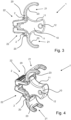
- FIGS. 3 and 4 show the mounting bracket 1 according to the invention in side view and in perspective view, respectively in the open state. To avoid repetition, the description of the Figures 1 and 2 referred to.
- FIG. 5 and 6 a second embodiment of the mounting bracket 1 according to the invention is shown in side view or perspective view.
- the essential difference to the design according to the previous figures is that the legs 20 can open and close even further and thus fishing rod sections with even larger and even smaller diameters can be accommodated.
- the legs 20 are designed differently in their clamping sections 21 so that their ends overlap when the mounting clamp 1 is closed and not in use. Accordingly, the front side 10a of the base body 10 is designed in steps to ensure that it rests against the side surfaces 11 of the base body 10 despite the different clamping sections 21 (see Fig.6 ). In the present example, the lower leg 20 can thus close further, whereby the free space 4 there can be significantly smaller than in the embodiment according to the previous figures and thus fishing rod sections with a small diameter can also be accommodated and clamped.
- the thickenings 22a at the ends of the handle sections 22 on the legs 20 are narrower than in the embodiment according to the previous figures.
- the thickening 22a is sufficient to accommodate the distal ends of the spring legs.
- the handle sections 22 of the legs 20 can thus be pressed together further, which causes the clamping sections 21 to open further and thus the mounting clamp 1 can also accommodate and clamp fishing rod sections with a large diameter.
- the angle between the handle section 22 and the clamping section 21 has also been reduced, which increases the distance between the thickenings 22a at the ends of the handle sections 22.
- This measure also means that the handle sections 22 of the legs 20 can be pressed together over a greater distance.
- the clamping sections 21 can thus be opened further and the mounting clamp 1 can also accommodate and clamp fishing rod sections with a large diameter.
- the mounting clamp 1 enables two fishing rod sections 30a, 30b of a telescopic rod 30 to be compactly connected to one another in a simple, quick and convenient manner, particularly for transport purposes.
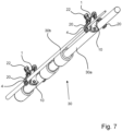
- Figure 7 a fishing rod 30 is shown, the two parts 30a, 30b of which are connected to one another with two mounting clamps 1 according to the invention.
- the individual fishing rod parts 30a, 30b are held with one hand, with the other hand the mounting clamp 1 or its legs 20 are opened on the lever arms of the handle section 22 by pressing the thumb and index finger together, the fishing rod parts 30a, 30b are guided into the free spaces 4 accessible through the opened legs 20 - see also Fig.
Landscapes
- Engineering & Computer Science (AREA)
- Mechanical Engineering (AREA)
- Life Sciences & Earth Sciences (AREA)
- Environmental Sciences (AREA)
- Animal Husbandry (AREA)
- Biodiversity & Conservation Biology (AREA)
Description
- Die Erfindung betrifft eine Montageklammer zum Transport von Angelruten.
- Angelruten werden zumeist als Teleskoprute oder als Steckrute ausgeführt. Bei Teleskopruten kann die Rute ineinandergeschoben werden. Zum Angeln wird die Rute auseinandergezogen und kann danach zu einem kompakten Paket ineinandergeschoben werden, so dass sie leicht zu transportieren ist. Diesem Vorteil bei Aufbau und Transport stehen jedoch einige Nachteile bei der Pflege und hinsichtlich der Belastbarkeit gegenüber, so dass häufig Steckruten verwendet werden. Die Steckrute besteht aus zwei oder mehr Angelrutenstücken. Zum Angeln werden die einzelnen Angelrutenstücke zu einer Rute zusammengesteckt und zum Transport zerlegt verpackt. Für den Transport wird die Angelschnur samt Köder meist montiert an der Angelrute belassen, wodurch die einzelnen Rutenelemente weiterhin miteinander verbunden bleiben.
- Problematisch bei Steckruten ist, dass sich beim Transport die zerlegten Angelrutenstücke nicht berühren sollten, denn durch daraus resultierende Schläge, Stöße oder Reibung können Kratzer, Knickungen und sonstigen Beschädigungen entstehen.
- Ein weiteres Problem, das während des Transports entsteht, ist das Sichern des Hakens. Der Haken ist typischerweise sehr spitz und mit einem Widerhaken ausgeführt, so dass es leicht zu Verletzungen oder Beschädigung an anderen Gegenständen kommen kann, wenn er nicht entsprechend gesichert ist. Das Sichern sollte hierbei nicht nur ein schlichtes Befestigen umfassen, so dass der Haken nicht unkontrolliert umherpendeln kann, sondern auch einen Schutz der Hakenspitze selbst bieten.
- Bekannt sind bspw. Klettbänder, mit denen die einzelnen Angelrutenstücke fest miteinander verschnürt werden. Hierbei kommt es unweigerlich zum ungewollten Kontakt der empfindlichen Einzelelemente oder des Griffstücks, so dass entsprechende Beschädigungen auftreten können. Außerdem wird das Anbringen der Klettbänder als vergleichsweise umständlich empfunden und ein Schutz vor dem spitzen Haken ist damit auch nicht zwingend gewährleistet.
- Aus der
US 3,113,363 ist eine Klemmvorrichtung bekannt, die mehrere voneinander beabstandete Aussparungen für die Aufnahme der einzelnen Angelrutenstücke aufweist. Zum Transport werden wenigstens zwei dieser Klemmvorrichtungen benötigt. Die einzelnen Angelrutenstücke werden dann in diese Aussparungen eingeklemmt und kommen aufgrund der Beabstandung nicht mehr in gegenseitige Berührung. Nachteilig ist hierbei jedoch der vergleichsweise unhandliche Zusammenbau der einzelnen Angelrutenstücke mit der Klemmvorrichtung und entsprechend auch die Demontage. Häufig muss die Angelrute nämlich auch dann transportiert werden, wenn lediglich der Platz gewechselt werden soll. Insbesondere in solchen Situationen besteht ein Bedarf, ohne viel Aufwand alle Einzelteile der Rute schnell transportfähig zu machen und dabei auch den Haken so sichern zu können, dass es durch ihn zu keinen Verletzungen und Beschädigungen kommen kann. - Des Weiteren ist aus der
US 5815894 A eine Klemmvorrichtung bekannt, mit der einzelne Angelrutenstücke voneinander beabstandet befestigt werden können. Die Klemmvorrichtung ist allerdings auf ein festes Verhältnis der Angelrutenstücke zueinander festgelegt. Dieses Verhältnis ist jedoch sehr selten gleich und somit nachteilig im Gebrauch. Ebenso steht der typischerweise konische Verlauf der Angelruten in keinem Verhältnis zueinander. - Die Aufgabe der Erfindung besteht somit darin, die einzelnen Angelrutenstücken einerseits so transportieren zu können, dass sie sich nicht berühren und damit gegenseitig beschädigen können, und gleichzeitig einfach, sicher, schnell und komfortabel zusammengepackt werden können.
- Die Aufgabe wird erfindungsgemäß gelöst durch eine Montageklammer mit den Merkmalen des Anspruchs 1. Vorteilhafte Ausgestaltungen der Erfindung sind in den Unteransprüchen angegeben.
- Erfindungsgemäß besteht die Montageklammer aus einem Grundkörper und zwei Schenkeln, die jeweils einen Klemmabschnitt und einen Griffabschnitt aufweisen. Die beiden Schenkel sind gegenüberliegend über wenigstens ein Gelenk, vorteilhafterweise über jeweils ein Gelenk, mit dem Grundkörper verbunden, und zwar derart, dass die Klemmabschnitte der Schenkel zumindest teilweise an den Seitenflächen des Grundkörpers anliegen und die Griffabschnitte über den Grundkörper hinausragend jeweils einen Hebelarm bilden. Bevorzugt ist das Gelenk zwischen dem Klemmabschnitt und dem Griffabschnitt angeordnet.
- Zwischen den beiden Schenkeln ist eine Feder angeordnet, die vorzugsweise als Schenkelfeder ausgebildet ist und die Schenkel so vorspannt, dass die beiden Klemmabschnitte aufeinander zugerichtet gegen den Grundkörper gepresst werden.
- Die Schenkel sind im Klemmabschnitt zumindest teilweise derart konvex nach außen gewölbt, dass sich in diesem Bereich jeweils zwischen den Innenseiten der Schenkel und den Seitenflächen des Grundkörpers ein Freiraum zur Aufnahme jeweils eines Teilstücks einer Angelrute ausbildet. Die beiden Freiräume sind dabei durch den Grundkörper voneinander definiert beabstandet.
- Der erste Vorteil der Erfindung besteht darin, zu Transportzwecken zwei Angelrutenstücke einer Steckrute durch den Klammermechanismus auf einfache, schnelle und komfortable Weise kompakt miteinander verbinden zu können. Mit einer Hand hält man die einzelnen Angelrutenstücke, mit der anderen Hand öffnet man die Montageklammern an den Hebelarmen des Griffabschnitts, führt die Angelrutenstücke jeweils in die durch die geöffnete Klammer zugänglichen Freiräume und schließt dann die Montageklammer wieder, so dass die zwei Angelrutenstücke parallel nebeneinander angeordnet und durch die Montageklammer fest miteinander verbunden sind. Es bietet sich die Verwendung von zwei Montageklammern an, die vorteilhafterweise jeweils in den Endbereichen der Angelrutenstücke angebracht werden. Wenn mehrere Angelrutenstücke miteinander verbunden werden sollen, lässt sich das durch weitere Montageklammern auf einfache Weise realisieren.
- Der zweite Vorteil der Erfindung besteht darin, dass die Freiräume und damit im montierten Zustand die Angelrutenstücke durch den Grundkörper räumlich voneinander getrennt sind. Der Grundkörper wirkt folglich nicht nur als Basiselement für die Schenkel, sondern gleichzeitig auch als Abstandshalter, der verhindert, dass sich die beiden Angelrutenstücke berühren und in Folge dessen aneinander reiben oder unvorteilhaft verbogen bzw. verformt werden können.
- Der dritte Vorteil ist darin zu sehen, dass die beiden Freiräume der Montageklammer völlig unabhängig voneinander genutzt werden können. Weder hat das Vorhandensein eines Angelrutenstücks in einem der Freiräume einen Einfluss auf den jeweils anderen Freiraum, noch beeinflusst der Durchmesser eines Angelrutenstücks die Klemmwirkung eines in dem entsprechend anderen Freiraum angeordneten Angelrutenstücks.
- In einer vorteilhaften Weiterbildung sind die Seitenflächen des Grundkörpers konkav gewölbt, um die Fixierung der Angelrutenstücke in dem Freiraum zu optimieren.
- In einer vorteilhaften Weiterbildung weisen die konvexen Wölbungen der Klemmabschnitte beider Schenkel unterschiedliche Radien auf, so dass sich unterschiedlich große Freiräume ausbilden. Aufgrund des sich verjüngenden Verlaufs der Angelrute weisen die einzelnen Angelrutenstücke eine unterschiedliche Dicke auf, so dass durch unterschiedlich große Freiräume eine optimale Fixierung der Angelrutenstücke gewährleistet ist.
- In einer vorteilhaften Weiterbildung ist die Feder als Schenkelfeder ausgebildet. Die Schenkel der Feder liegen dabei jeweils an der Innenseite des Griffabschnitts der beiden Montageklammerschenkel an. Vorteilhafterweise liegen die Schenkel der Feder nicht nur an den Innenseiten des Griffabschnitts an, sondern die distalen Enden der Federschenkel sind in eine Ausnehmung eingeführt. Hierfür weist das Ende des Griffabschnitts eine Verdickung auf. Durch dieses Einführen in die Ausnehmung wird die Feder zum einen an einem seitlichen Verrutschen gehindert. Zum anderen ist die Feder an einer Bewegung in Richtung des Griffabschnitts gehindert und kann sich folglich beim Zusammendrücken der Hebelarme des Griffabschnitts nur in Richtung des Klemmabschnitts bewegen.
- In einer vorteilhaften Weiterbildung weist der Grundkörper eine Durchgangsbohrung und/oder eine Öse auf, die jeweils zum Einführen eines Angelhakens und/oder eines Karabiners, auch Snap genannt, und/oder eines Angelköders geeignet ist bzw. sind. Dadurch kann die Angelschnur mit oder ohne Köder fixiert und ein unkontrolliertes Umherpendeln vermieden werden. Während es sich anbietet, den spitzen Angelhaken in die Durchgangsbohrung einzuführen, da dieser dann vollständig verdeckt ist und dadurch Verletzungen und Beschädigungen verhindert werden können, ist die Fixierung des Karabiners oder des Angelköders an der Öse vorteilhaft.
- In einer vorteilhaften Weiterbildung ist die Montageklammer im Spritzguss- oder 3D-Druck-Verfahren hergestellt. Die Herstellung ist somit vergleichsweise einfach und kostengünstig möglich.
- In einer besonders vorteilhaften Weiterbildung überlappen sich die Enden der Schenkel im geschlossenen und unbenutzten Zustand der Montageklammer. Dadurch können sich die Schenkel weiter schließen, wodurch der Freiraum im kleiner werden kann und somit auch Angelrutenstücke mit kleinem Durchmesser aufgenommen und verklemmt werden können.
- Nachfolgend wird die Erfindung anhand von Ausführungsbeispielen unter Bezugnahme auf die Zeichnungen näher erläutert.
- Es zeigen schematisch:
- Figur 1
- eine Seitenansicht der erfindungsgemäßen Montageklammer in geschlossenem Zustand,
- Figur 2
- eine perspektivische Ansicht der erfindungsgemäßen Montageklammer in geschlossenem Zustand,
- Figur 3
- eine Seitenansicht der erfindungsgemäßen Montageklammer in geöffnetem Zustand,
- Figur 4
- eine perspektivische Ansicht der erfindungsgemäßen Montageklammer in geöffnetem Zustand,
- Figur 5
- eine Seitenansicht einer zweiten Ausführungsform der erfindungsgemäßen Montageklammer in geschlossenem Zustand,
- Figur 6
- eine perspektivische Ansicht einer zweiten Ausführungsform der erfindungsgemäßen Montageklammer in geschlossenem Zustand und
- Figur 7
- eine transportfähige Angelrute mit zwei erfindungsgemäßen Montageklammern.
- Bei der nachfolgenden Beschreibung der bevorzugten Ausführungsformen bezeichnen gleiche Bezugszeichen gleiche oder vergleichbare Komponenten.
- In
Figur 1 ist die erfindungsgemäße Montageklammer 1 in Seitenansicht gezeigt und inFigur 2 in perspektivischer Ansicht, wobei die Montageklammer 1 jeweils im geschlossenen Zustand abgebildet ist. Die Montageklammer 1 besteht im Wesentlichen aus einem Grundkörper 10 und zwei Schenkeln 20. Die Schenkel 20 sind dabei jeweils in einen Klemmabschnitt 21 und einen Griffabschnitt 22 unterteilt. - Im Bereich des Übergangs zwischen Klemmabschnitt 21 und Griffabschnitt 22 befindet sich jeweils ein Gelenk 2, über das die beiden Schenkel 20 gegenüberliegend jeweils verdrehbar mit dem Grundkörper 10 verbunden sind. Die Klemmabschnitte 21 der Schenkel 20 liegen in geschlossenem Zustand zumindest teilweise an den Seitenflächen 11 des Grundkörpers 10 an, wie bspw. aus
Fig. 2 ersichtlich, wodurch ein Anschlag gebildet wird. Die Griffabschnitte 22 ragen jeweils über den Grundkörper 10 hinaus und bilden einen Hebelarm. Zwischen den beiden Schenkeln 20 ist eine Schenkelfeder 3 angeordnet, die die Schenkel 20 so vorspannt, dass die beiden Klemmabschnitte 21 aufeinander zugerichtet gegen den Grundkörper 10 gepresst werden. Der erwähnte Anschlag begrenzt die Beweglichkeit der Schenkel 20 in geschlossenem Zustand. - Die Schenkel der Feder 3 liegen dabei jeweils an der Innenseite des Griffabschnitts 22 der beiden Montageklammerschenkel 20 an. Vorteilhafterweise liegen die Schenkel der Feder 3 nicht nur an den Innenseiten des Griffabschnitts 22 an, sondern die distalen Enden der Federschenkel sind in eine Ausnehmung eingeführt (nicht dargestellt). Hierfür weist das Ende des Griffabschnitts 22 eine Verdickung 22a auf.
- Indem man die Montageklammer 1 an den Hebelarmen des Griffabschnitts 22 vorzugsweise zwischen Daumen und Zeigefinger nimmt und gegen die Federkraft zusammendrückt, lässt sich die Montageklammer 1 einhändig auf einfache Weise öffnen und dann wieder schließen.
- Wie aus den Figuren ersichtlich sind die Schenkel 20 im Klemmabschnitt 21 konvex nach außen gewölbt, während die Seitenflächen 11 des Grundkörpers 10 konkav gewölbt sind, so dass sich in diesem Bereich jeweils zwischen den Innenseiten 23 der Schenkel 20 und den Seitenflächen 11 des Grundkörpers 10 ein Freiraum 4 ausbildet. In diesen Freiraum 4 wird im Anwendungsfall ein Teilstück einer auseinandergebauten Angelrute 30 eingeklemmt. Im montierten Zustand, wie er in
Figur 5 dargestellt ist, ist die Montageklammer 1 somit orthogonal zur Längsrichtung der Angelrutenteilstücke 30a, 30b ausgerichtet. Dabei sollte der Durchmesser des Angelrutenteilstücks 30a, 30b größer sein als der Abstand zwischen den Seitenflächen 11, 23 von Grundkörper 10 und Schenkel 20, um eine entsprechende Klemmwirkung zu erzielen. Da die Angelrute 30 typischerweise einen konischen Verlauf hat und damit der Durchmesser der Angelrute 30 vom Griffstück bis zur Spitze allmählich kleiner wird, sind die beiden Freiräume 4 der Montageklammer 1 vorteilhafterweise unterschiedlich groß ausgeführt, indem die konvexe bzw. konkave Wölbung des Klemmabschnitts 21 bzw. des Grundkörpers 10 auf beiden Seiten unterschiedlich ausfällt. - Das entscheidende Merkmal der Montageklammer 1 ist, dass die beiden Freiräume 4 durch den Grundkörper voneinander definiert beabstandet sind. Wenn im Anwendungsfall (siehe
Fig. 5 ) in jedem Freiraum 4 ein Angelrutenteilstück 30a, 30b eingeklemmt wurde, wird durch diese räumliche Beabstandung verhindert, dass sich die beiden Angelrutenstücke berühren und in Folge dessen aneinander reiben können. - In
Fig. 1 ist zudem am Grundkörper 10 eine Durchgangsbohrung 12 sowie eine Öse 13 zu erkennen. Beides ist jeweils zum Einführen eines Angelhakens und/oder eines Karabiners, auch Snap genannt, und/oder eines Angelköders vorgesehen. Die Durchgangsbohrung 12 ist vorteilhafterweise dafür zu verwenden, dass der vergleichsweise spitze Angelhaken darin eingeführt und aufgrund der Schnurspannung gehalten wird. An der Öse 13 lässt sich bei demontiertem Köder einfach und schnell der Karabiner befestigen. - Für eine kompakte Ausgestaltung ist die Montageklammer idealerweise etwa 4-5 cm lang und hat im geschlossenen Zustand im Bereich des Klemmabschnitts eine maximale Breite von ca. 3 cm und im Bereich des Griffabschnitts von ca. 5 cm.
- Die
Figuren 3 und 4 zeigen die erfindungsgemäße Montageklammer 1 in Seitenansicht bzw. in perspektivischer Ansicht jeweils im geöffneten Zustand. Zur Vermeidung von Wiederholungen wird auf die Beschreibung derFiguren 1 und 2 verwiesen. - In
Figur 5 und 6 ist eine zweite Ausführungsform der erfindungsgemäßen Montageklammer 1 in Seitenansicht bzw. perspektivischer Ansicht gezeigt. Der wesentliche Unterschied zur Ausführung gemäß den vorherigen Figuren besteht darin, dass sich die Schenkel 20 noch weiter öffnen und schließen können und damit Angelrutenstücke mit noch größerem und noch kleinerem Durchmesser aufgenommen werden können. - Hierfür sind zum einen die Schenkel 20 in ihren Klemmabschnitten 21 derart unterschiedlich ausgeführt, dass sich ihre Enden im geschlossenen und unbenutzten Zustand der Montageklammer 1 überlappen. Entsprechend ist die Stirnseite 10a des Grundkörpers 10 stufenartig ausgebildet, um das Anliegen an den Seitenflächen 11 des Grundkörpers 10 trotz der unterschiedlichen Klemmabschnitte 21 zu gewährleisten (siehe
Fig. 6 ). Dadurch kann sich im vorliegenden Beispiel der untere Schenkel 20 weiter schließen, wodurch der dortige Freiraum 4 gegenüber der Ausführung gemäß den vorherigen Figuren deutlich kleiner werden kann und somit auch Angelrutenstücke mit kleinem Durchmesser aufgenommen und geklemmt werden können. - Des Weiteren sind an den Schenkeln 20 die Verdickungen 22a an den Enden der Griffabschnitte 22 gegenüber der Ausführung gemäß den vorherigen Figuren schmaler ausgeführt. Die Verdickung 22a ist dabei ausreichend, um die distalen Enden der Federschenkel aufzunehmen. Die Griffabschnitte 22 der Schenkel 20 lassen sich dadurch weiter zusammendrücken, wodurch sich die Klemmabschnitte 21 weiter öffnen und damit die Montageklammer 1 auch Angelrutenstücke mit großem Durchmesser aufnehmen und klemmen kann.
- Gegenüber der Ausführung gemäß den vorherigen Figuren ist außerdem der Winkel zwischen Griffabschnitt 22 und Klemmabschnitt 21 verringert worden, wodurch sich der Abstand zwischen den Verdickungen 22a an den Enden der Griffabschnitte 22 vergrößert. Auch diese Maßnahme führt dazu, dass sich die Griffabschnitte 22 der Schenkel 20 über einen weiteren Weg zusammendrücken lassen. Die Klemmabschnitte 21 lassen sich somit weiter öffnen und die Montageklammer 1 kann auch Angelrutenstücke mit großem Durchmesser aufnehmen und klemmen.
- Die grundsätzliche Funktionalität der Ausführungsform gemäß
Fig 5 und 6 entspricht dabei der der vorherigen Figuren, so dass zur Vermeidung von Wiederholungen auf die Beschreibung derFiguren 1 und 2 verwiesen wird. - Durch die erfindungsgemäße Montageklammer 1 können insbesondere zu Transportzwecken zwei Angelrutenstücke 30a, 30b einer Steckrute 30 auf einfache, schnelle und komfortable Weise kompakt miteinander verbunden werden. In
Figur 7 ist eine Angelrute 30 abgebildet, deren zwei Teilstücke 30a, 30b mit zwei erfindungsgemäßen Montageklammern 1 miteinander verbunden sind. Man hält mit einer Hand die einzelnen Angelrutenstücke 30a, 30b, mit der anderen Hand öffnet man die Montageklammer 1 bzw. deren Schenkel 20 an den Hebelarmen des Griffabschnitts 22 durch Zusammendrücken von Daumen und Zeigefinger, führt die Angelrutenstücke 30a, 30b jeweils in die durch die geöffneten Schenkel 20 zugänglichen Freiräume 4 - siehe auchFig. 3 und 4 - und schließt dann die Schenkel 20 wieder, so dass die zwei Angelrutenstücke 30a, 30b parallel nebeneinander durch den Grundkörper 10 beabstandet angeordnet sind und durch die Montageklammer 1 fest miteinander verbunden sind. Es bietet sich, wie inFig. 7 dargestellt, die Verwendung von zwei Montageklammern 1 an, die vorteilhafterweise jeweils in den Endbereichen der Angelrutenstücke 30a, 30b angebracht werden. Wenn noch mehr Angelrutenstücke miteinander verbunden werden sollen, lässt sich das durch weitere Montageklammern 1 auf einfache Weise realisieren. -
- 1
- Montageklammer
- 2
- Gelenk
- 3
- Feder
- 4
- Freiraum
- 10
- Grundkörper
- 10a
- Stirnseite des Grundkörpers
- 11
- Seitenfläche des Grundkörpers
- 12
- Durchgangsbohrung
- 13
- Öse
- 20
- Schenkel
- 21
- Klemmabschnitt
- 22
- Griffabschnitt
- 22a
- Verdickung
- 23
- Schenkelinnenseite
- 30
- Angelrute
- 30a
- erstes Teilstück der Angelrute
- 30b
- zweites Teilstück der Angelrute
Claims (11)
- Montageklammer (1) zum Transport von Angelruten (30), mit einem Grundkörper (10) und zwei Schenkeln (20), die jeweils einen Klemmabschnitt (21) und einen Griffabschnitt (22) aufweisen,wobei die beiden Schenkel (20) gegenüberliegend über wenigstens ein Gelenk (2) mit dem Grundkörper (10) verbunden sind, derart, dass die Klemmabschnitte (21) der Schenkel (20) zumindest teilweise an Seitenflächen (11) des Grundkörpers (10) anliegen und die Griffabschnitte (22) über den Grundkörper (10) hinausragend jeweils einen Hebelarm bilden,wobei zwischen den beiden Schenkeln (20) eine Feder (3) angeordnet ist, die die Schenkel (20) so vorspannt, dass die beiden Klemmabschnitte (21) aufeinander zugerichtet gegen den Grundkörper (10) gepresst werden,und wobei die Schenkel (20) im Klemmabschnitt (21) zumindest teilweise derart konvex nach außen gewölbt sind, dass sich in diesem Bereich jeweils zwischen Innenseiten (23) der Schenkel (20) und den Seitenflächen (11) des Grundkörpers (10) ein Freiraum (4) zur Aufnahme jeweils eines Teilstücks (30a, 30b) einer Angelrute (30) ausbildet und die beiden Freiräume (4) durch den Grundkörper (10) voneinander definiert beabstandet sind.
- Montageklammer (1) nach Anspruch 1,
wobei das Gelenk (2) zwischen dem Klemmabschnitt (21) und dem Griffabschnitt (22) angeordnet ist. - Montageklammer (1) nach Anspruch 1 oder 2,
wobei die beiden Schenkel (20) gegenüberliegend über jeweils ein Gelenk (2) mit dem Grundkörper (10) verbunden sind. - Montageklammer (1) nach einem der vorhergehenden Ansprüche,
wobei die Seitenflächen (11) des Grundkörpers (10) konkav gewölbt sind. - Montageklammer (1) nach einem der vorhergehenden Ansprüche,
wobei die konvexen Wölbungen der Klemmabschnitte (21) beider Schenkel (20) unterschiedliche Radien aufweisen, so dass sich unterschiedlich große Freiräume (4) ausbilden. - Montageklammer (1) nach einem der vorhergehenden Ansprüche,
wobei die Feder (3) als Schenkelfeder ausgebildet ist und die Schenkel der Feder (3) jeweils an der Innenseite des Griffabschnitts (22) der beiden Schenkel (20) der Montageklammer (1) anliegen. - Montageklammer (1) nach Anspruch 6,
wobei an den Innenseiten des Griffabschnitts (22) jeweils eine Ausnehmung angeordnet ist, in die die distalen Enden der Schenkelfeder (3) eingeführt sind. - Montageklammer (1) nach einem der vorhergehenden Ansprüche,
wobei der Grundkörper (10) eine Durchgangsbohrung (12) aufweist, die zum Einführen eines Angelhakens und/oder eines Karabiners und/oder eines Angelköders geeignet ist. - Montageklammer (1) nach einem der vorhergehenden Ansprüche,
wobei an dem Grundkörper (10) eine Öse (13) angeordnet ist, die die zum Einführen eines Angelhakens und/oder eines Karabiners und/oder eines Angelköders geeignet ist. - Montageklammer (1) nach einem der vorhergehenden Ansprüche,
wobei die Montageklammer im Spritzguss- oder 3D-Druck-Verfahren hergestellt ist. - Montageklammer (1) nach einem der vorhergehenden Ansprüche,
wobei sich die Enden der Schenkel (20) im geschlossenen und unbenutzten Zustand der Montageklammer (1) überlappen.
Applications Claiming Priority (1)
| Application Number | Priority Date | Filing Date | Title |
|---|---|---|---|
| DE102021005155.6A DE102021005155B4 (de) | 2021-10-15 | 2021-10-15 | Montageklammer zum Transport von Angelruten |
Publications (2)
| Publication Number | Publication Date |
|---|---|
| EP4165986A1 EP4165986A1 (de) | 2023-04-19 |
| EP4165986B1 true EP4165986B1 (de) | 2024-07-17 |
Family
ID=83688809
Family Applications (1)
| Application Number | Title | Priority Date | Filing Date |
|---|---|---|---|
| EP22200071.3A Active EP4165986B1 (de) | 2021-10-15 | 2022-10-06 | Montageklammer zum transport von angelruten |
Country Status (3)
| Country | Link |
|---|---|
| EP (1) | EP4165986B1 (de) |
| DE (1) | DE102021005155B4 (de) |
| PL (1) | PL4165986T3 (de) |
Family Cites Families (4)
| Publication number | Priority date | Publication date | Assignee | Title |
|---|---|---|---|---|
| US3113363A (en) | 1960-03-28 | 1963-12-10 | Donald J Fyvie | Fishing rod clamping apparatus |
| US3832796A (en) * | 1973-08-10 | 1974-09-03 | J Cardwell | Fishing rod holder |
| US5815894A (en) | 1996-05-28 | 1998-10-06 | Soriano; Brian F. | System for handling long items |
| US6584725B1 (en) * | 2002-07-18 | 2003-07-01 | Joanne Elam | Fishing rod clips |
-
2021
- 2021-10-15 DE DE102021005155.6A patent/DE102021005155B4/de not_active Expired - Fee Related
-
2022
- 2022-10-06 EP EP22200071.3A patent/EP4165986B1/de active Active
- 2022-10-06 PL PL22200071.3T patent/PL4165986T3/pl unknown
Also Published As
| Publication number | Publication date |
|---|---|
| PL4165986T3 (pl) | 2024-11-25 |
| DE102021005155A1 (de) | 2023-04-20 |
| EP4165986A1 (de) | 2023-04-19 |
| DE102021005155B4 (de) | 2023-05-17 |
Similar Documents
| Publication | Publication Date | Title |
|---|---|---|
| DE69616077T2 (de) | Sicherheitskarabinerhaken | |
| DE60024057T2 (de) | Knebelbolzen | |
| EP2792288B1 (de) | Rastvorrichtung für ein Staubsauger-Saugrohr | |
| WO2008025587A1 (de) | Tierfalle | |
| DE2220550C3 (de) | Spannvorrichtung zum Aufbringen einer Zugkraft zwischen einem ersten und einem zweiten flexiblen Verbindungselement | |
| DE3128169C2 (de) | Abnehmbarer Tragegriff | |
| DE20022057U1 (de) | Rohrförmige Teleskopeinrichtung | |
| DE112013007559B4 (de) | Schlauchklemme | |
| EP3247283B1 (de) | Vorrichtung zum festklemmen eines medizinischen führungsdrahtes | |
| EP4165986B1 (de) | Montageklammer zum transport von angelruten | |
| EP0706316B1 (de) | Kescher, insbesondere für den fischfang | |
| EP2084951B1 (de) | Unterlenkerzusammenbau für eine Anbaueinrichtung eines Traktors | |
| DE69715763T2 (de) | Angelschnur-Einführeinsatz für Angelrute mit innerer Schnurführung | |
| DE2362931A1 (de) | Klemmbuegel zum festklemmen eines oder mehrerer rohre, kabel oder aehnlicher laenglicher gegenstaende | |
| DE4436726A1 (de) | Vorrichtung zum schnellen Anbringen von Tauchgerätezylindern an dem Rücken einer Stabilisatorjacke oder ähnlichem und Lösen von dieser | |
| DE3001195A1 (de) | Schnappvorrichtung zur loesbaren verbindung von zwei teilen oder brettern | |
| DE3147783A1 (de) | Geraet zur viehgeburtshilfe | |
| DE2221633C3 (de) | Bauteil für Rundgliederketten | |
| DE102014015220A1 (de) | Klappmesser | |
| DE2238668A1 (de) | Drahtzange mit haltevorrichtung fuer das abgekniffene drahtende | |
| DE1287272B (de) | Vorhanggleiter | |
| DE814680C (de) | Fischfanggeraet, insbesondere Kescher und Gaff | |
| DE7734968U1 (de) | Lasche fuer fahrradrahmen | |
| DE2748113C2 (de) | ||
| DE102015013344B4 (de) | Vorrichtung zur befestigung eines objektes an einem oder mehreren trägerstoffen |
Legal Events
| Date | Code | Title | Description |
|---|---|---|---|
| PUAI | Public reference made under article 153(3) epc to a published international application that has entered the european phase |
Free format text: ORIGINAL CODE: 0009012 |
|
| STAA | Information on the status of an ep patent application or granted ep patent |
Free format text: STATUS: THE APPLICATION HAS BEEN PUBLISHED |
|
| AK | Designated contracting states |
Kind code of ref document: A1 Designated state(s): AL AT BE BG CH CY CZ DE DK EE ES FI FR GB GR HR HU IE IS IT LI LT LU LV MC ME MK MT NL NO PL PT RO RS SE SI SK SM TR |
|
| STAA | Information on the status of an ep patent application or granted ep patent |
Free format text: STATUS: REQUEST FOR EXAMINATION WAS MADE |
|
| 17P | Request for examination filed |
Effective date: 20231004 |
|
| RBV | Designated contracting states (corrected) |
Designated state(s): AL AT BE BG CH CY CZ DE DK EE ES FI FR GB GR HR HU IE IS IT LI LT LU LV MC ME MK MT NL NO PL PT RO RS SE SI SK SM TR |
|
| RIC1 | Information provided on ipc code assigned before grant |
Ipc: B25B 5/10 20060101ALI20240122BHEP Ipc: A01K 97/08 20060101AFI20240122BHEP |
|
| GRAP | Despatch of communication of intention to grant a patent |
Free format text: ORIGINAL CODE: EPIDOSNIGR1 |
|
| STAA | Information on the status of an ep patent application or granted ep patent |
Free format text: STATUS: GRANT OF PATENT IS INTENDED |
|
| INTG | Intention to grant announced |
Effective date: 20240312 |
|
| GRAS | Grant fee paid |
Free format text: ORIGINAL CODE: EPIDOSNIGR3 |
|
| GRAA | (expected) grant |
Free format text: ORIGINAL CODE: 0009210 |
|
| STAA | Information on the status of an ep patent application or granted ep patent |
Free format text: STATUS: THE PATENT HAS BEEN GRANTED |
|
| AK | Designated contracting states |
Kind code of ref document: B1 Designated state(s): AL AT BE BG CH CY CZ DE DK EE ES FI FR GB GR HR HU IE IS IT LI LT LU LV MC ME MK MT NL NO PL PT RO RS SE SI SK SM TR |
|
| REG | Reference to a national code |
Ref country code: CH Ref legal event code: EP |
|
| REG | Reference to a national code |
Ref country code: DE Ref legal event code: R096 Ref document number: 502022001248 Country of ref document: DE |
|
| REG | Reference to a national code |
Ref country code: IE Ref legal event code: FG4D Free format text: LANGUAGE OF EP DOCUMENT: GERMAN |
|
| REG | Reference to a national code |
Ref country code: SE Ref legal event code: TRGR |
|
| REG | Reference to a national code |
Ref country code: LT Ref legal event code: MG9D |
|
| REG | Reference to a national code |
Ref country code: NL Ref legal event code: MP Effective date: 20240717 |
|
| PG25 | Lapsed in a contracting state [announced via postgrant information from national office to epo] |
Ref country code: PT Free format text: LAPSE BECAUSE OF FAILURE TO SUBMIT A TRANSLATION OF THE DESCRIPTION OR TO PAY THE FEE WITHIN THE PRESCRIBED TIME-LIMIT Effective date: 20241118 |
|
| PG25 | Lapsed in a contracting state [announced via postgrant information from national office to epo] |
Ref country code: NL Free format text: LAPSE BECAUSE OF FAILURE TO SUBMIT A TRANSLATION OF THE DESCRIPTION OR TO PAY THE FEE WITHIN THE PRESCRIBED TIME-LIMIT Effective date: 20240717 |
|
| PG25 | Lapsed in a contracting state [announced via postgrant information from national office to epo] |
Ref country code: PT Free format text: LAPSE BECAUSE OF FAILURE TO SUBMIT A TRANSLATION OF THE DESCRIPTION OR TO PAY THE FEE WITHIN THE PRESCRIBED TIME-LIMIT Effective date: 20241118 Ref country code: NL Free format text: LAPSE BECAUSE OF FAILURE TO SUBMIT A TRANSLATION OF THE DESCRIPTION OR TO PAY THE FEE WITHIN THE PRESCRIBED TIME-LIMIT Effective date: 20240717 |
|
| PG25 | Lapsed in a contracting state [announced via postgrant information from national office to epo] |
Ref country code: NO Free format text: LAPSE BECAUSE OF FAILURE TO SUBMIT A TRANSLATION OF THE DESCRIPTION OR TO PAY THE FEE WITHIN THE PRESCRIBED TIME-LIMIT Effective date: 20241017 |
|
| PG25 | Lapsed in a contracting state [announced via postgrant information from national office to epo] |
Ref country code: GR Free format text: LAPSE BECAUSE OF FAILURE TO SUBMIT A TRANSLATION OF THE DESCRIPTION OR TO PAY THE FEE WITHIN THE PRESCRIBED TIME-LIMIT Effective date: 20241018 Ref country code: FI Free format text: LAPSE BECAUSE OF FAILURE TO SUBMIT A TRANSLATION OF THE DESCRIPTION OR TO PAY THE FEE WITHIN THE PRESCRIBED TIME-LIMIT Effective date: 20240717 |
|
| PG25 | Lapsed in a contracting state [announced via postgrant information from national office to epo] |
Ref country code: BG Free format text: LAPSE BECAUSE OF FAILURE TO SUBMIT A TRANSLATION OF THE DESCRIPTION OR TO PAY THE FEE WITHIN THE PRESCRIBED TIME-LIMIT Effective date: 20240717 |
|
| PG25 | Lapsed in a contracting state [announced via postgrant information from national office to epo] |
Ref country code: LV Free format text: LAPSE BECAUSE OF FAILURE TO SUBMIT A TRANSLATION OF THE DESCRIPTION OR TO PAY THE FEE WITHIN THE PRESCRIBED TIME-LIMIT Effective date: 20240717 |
|
| PG25 | Lapsed in a contracting state [announced via postgrant information from national office to epo] |
Ref country code: IS Free format text: LAPSE BECAUSE OF FAILURE TO SUBMIT A TRANSLATION OF THE DESCRIPTION OR TO PAY THE FEE WITHIN THE PRESCRIBED TIME-LIMIT Effective date: 20241117 |
|
| PG25 | Lapsed in a contracting state [announced via postgrant information from national office to epo] |
Ref country code: HR Free format text: LAPSE BECAUSE OF FAILURE TO SUBMIT A TRANSLATION OF THE DESCRIPTION OR TO PAY THE FEE WITHIN THE PRESCRIBED TIME-LIMIT Effective date: 20240717 |
|
| PG25 | Lapsed in a contracting state [announced via postgrant information from national office to epo] |
Ref country code: ES Free format text: LAPSE BECAUSE OF FAILURE TO SUBMIT A TRANSLATION OF THE DESCRIPTION OR TO PAY THE FEE WITHIN THE PRESCRIBED TIME-LIMIT Effective date: 20240717 Ref country code: RS Free format text: LAPSE BECAUSE OF FAILURE TO SUBMIT A TRANSLATION OF THE DESCRIPTION OR TO PAY THE FEE WITHIN THE PRESCRIBED TIME-LIMIT Effective date: 20241017 |
|
| PG25 | Lapsed in a contracting state [announced via postgrant information from national office to epo] |
Ref country code: RS Free format text: LAPSE BECAUSE OF FAILURE TO SUBMIT A TRANSLATION OF THE DESCRIPTION OR TO PAY THE FEE WITHIN THE PRESCRIBED TIME-LIMIT Effective date: 20241017 Ref country code: NO Free format text: LAPSE BECAUSE OF FAILURE TO SUBMIT A TRANSLATION OF THE DESCRIPTION OR TO PAY THE FEE WITHIN THE PRESCRIBED TIME-LIMIT Effective date: 20241017 Ref country code: LV Free format text: LAPSE BECAUSE OF FAILURE TO SUBMIT A TRANSLATION OF THE DESCRIPTION OR TO PAY THE FEE WITHIN THE PRESCRIBED TIME-LIMIT Effective date: 20240717 Ref country code: IS Free format text: LAPSE BECAUSE OF FAILURE TO SUBMIT A TRANSLATION OF THE DESCRIPTION OR TO PAY THE FEE WITHIN THE PRESCRIBED TIME-LIMIT Effective date: 20241117 Ref country code: HR Free format text: LAPSE BECAUSE OF FAILURE TO SUBMIT A TRANSLATION OF THE DESCRIPTION OR TO PAY THE FEE WITHIN THE PRESCRIBED TIME-LIMIT Effective date: 20240717 Ref country code: GR Free format text: LAPSE BECAUSE OF FAILURE TO SUBMIT A TRANSLATION OF THE DESCRIPTION OR TO PAY THE FEE WITHIN THE PRESCRIBED TIME-LIMIT Effective date: 20241018 Ref country code: FI Free format text: LAPSE BECAUSE OF FAILURE TO SUBMIT A TRANSLATION OF THE DESCRIPTION OR TO PAY THE FEE WITHIN THE PRESCRIBED TIME-LIMIT Effective date: 20240717 Ref country code: ES Free format text: LAPSE BECAUSE OF FAILURE TO SUBMIT A TRANSLATION OF THE DESCRIPTION OR TO PAY THE FEE WITHIN THE PRESCRIBED TIME-LIMIT Effective date: 20240717 Ref country code: BG Free format text: LAPSE BECAUSE OF FAILURE TO SUBMIT A TRANSLATION OF THE DESCRIPTION OR TO PAY THE FEE WITHIN THE PRESCRIBED TIME-LIMIT Effective date: 20240717 |
|
| PG25 | Lapsed in a contracting state [announced via postgrant information from national office to epo] |
Ref country code: RO Free format text: LAPSE BECAUSE OF FAILURE TO SUBMIT A TRANSLATION OF THE DESCRIPTION OR TO PAY THE FEE WITHIN THE PRESCRIBED TIME-LIMIT Effective date: 20240717 Ref country code: DK Free format text: LAPSE BECAUSE OF FAILURE TO SUBMIT A TRANSLATION OF THE DESCRIPTION OR TO PAY THE FEE WITHIN THE PRESCRIBED TIME-LIMIT Effective date: 20240717 Ref country code: SM Free format text: LAPSE BECAUSE OF FAILURE TO SUBMIT A TRANSLATION OF THE DESCRIPTION OR TO PAY THE FEE WITHIN THE PRESCRIBED TIME-LIMIT Effective date: 20240717 |
|
| REG | Reference to a national code |
Ref country code: DE Ref legal event code: R097 Ref document number: 502022001248 Country of ref document: DE |
|
| PG25 | Lapsed in a contracting state [announced via postgrant information from national office to epo] |
Ref country code: EE Free format text: LAPSE BECAUSE OF FAILURE TO SUBMIT A TRANSLATION OF THE DESCRIPTION OR TO PAY THE FEE WITHIN THE PRESCRIBED TIME-LIMIT Effective date: 20240717 |
|
| PG25 | Lapsed in a contracting state [announced via postgrant information from national office to epo] |
Ref country code: CZ Free format text: LAPSE BECAUSE OF FAILURE TO SUBMIT A TRANSLATION OF THE DESCRIPTION OR TO PAY THE FEE WITHIN THE PRESCRIBED TIME-LIMIT Effective date: 20240717 |
|
| PG25 | Lapsed in a contracting state [announced via postgrant information from national office to epo] |
Ref country code: SK Free format text: LAPSE BECAUSE OF FAILURE TO SUBMIT A TRANSLATION OF THE DESCRIPTION OR TO PAY THE FEE WITHIN THE PRESCRIBED TIME-LIMIT Effective date: 20240717 |
|
| PLBE | No opposition filed within time limit |
Free format text: ORIGINAL CODE: 0009261 |
|
| STAA | Information on the status of an ep patent application or granted ep patent |
Free format text: STATUS: NO OPPOSITION FILED WITHIN TIME LIMIT |
|
| 26N | No opposition filed |
Effective date: 20250422 |
|
| PG25 | Lapsed in a contracting state [announced via postgrant information from national office to epo] |
Ref country code: MC Free format text: LAPSE BECAUSE OF FAILURE TO SUBMIT A TRANSLATION OF THE DESCRIPTION OR TO PAY THE FEE WITHIN THE PRESCRIBED TIME-LIMIT Effective date: 20240717 |
|
| PG25 | Lapsed in a contracting state [announced via postgrant information from national office to epo] |
Ref country code: BE Free format text: LAPSE BECAUSE OF NON-PAYMENT OF DUE FEES Effective date: 20241031 Ref country code: LU Free format text: LAPSE BECAUSE OF NON-PAYMENT OF DUE FEES Effective date: 20241006 |
|
| REG | Reference to a national code |
Ref country code: BE Ref legal event code: MM Effective date: 20241031 |
|
| PGFP | Annual fee paid to national office [announced via postgrant information from national office to epo] |
Ref country code: PL Payment date: 20241217 Year of fee payment: 4 |
|
| PGFP | Annual fee paid to national office [announced via postgrant information from national office to epo] |
Ref country code: FR Payment date: 20250930 Year of fee payment: 4 |
|
| PG25 | Lapsed in a contracting state [announced via postgrant information from national office to epo] |
Ref country code: IE Free format text: LAPSE BECAUSE OF NON-PAYMENT OF DUE FEES Effective date: 20241006 |
|
| PGFP | Annual fee paid to national office [announced via postgrant information from national office to epo] |
Ref country code: DE Payment date: 20251031 Year of fee payment: 4 |
|
| PGFP | Annual fee paid to national office [announced via postgrant information from national office to epo] |
Ref country code: AT Payment date: 20260113 Year of fee payment: 4 |
|
| PGFP | Annual fee paid to national office [announced via postgrant information from national office to epo] |
Ref country code: SE Payment date: 20251002 Year of fee payment: 4 |
|
| PG25 | Lapsed in a contracting state [announced via postgrant information from national office to epo] |
Ref country code: IT Free format text: LAPSE BECAUSE OF FAILURE TO SUBMIT A TRANSLATION OF THE DESCRIPTION OR TO PAY THE FEE WITHIN THE PRESCRIBED TIME-LIMIT Effective date: 20240717 Ref country code: CY Free format text: LAPSE BECAUSE OF FAILURE TO SUBMIT A TRANSLATION OF THE DESCRIPTION OR TO PAY THE FEE WITHIN THE PRESCRIBED TIME-LIMIT; INVALID AB INITIO Effective date: 20221006 |
|
| PG25 | Lapsed in a contracting state [announced via postgrant information from national office to epo] |
Ref country code: HU Free format text: LAPSE BECAUSE OF FAILURE TO SUBMIT A TRANSLATION OF THE DESCRIPTION OR TO PAY THE FEE WITHIN THE PRESCRIBED TIME-LIMIT; INVALID AB INITIO Effective date: 20221006 |