EP4166043A1 - Système d'assise modulaire - Google Patents
Système d'assise modulaire Download PDFInfo
- Publication number
- EP4166043A1 EP4166043A1 EP22191844.4A EP22191844A EP4166043A1 EP 4166043 A1 EP4166043 A1 EP 4166043A1 EP 22191844 A EP22191844 A EP 22191844A EP 4166043 A1 EP4166043 A1 EP 4166043A1
- Authority
- EP
- European Patent Office
- Prior art keywords
- seat
- connector components
- arm
- side wall
- seating system
- Prior art date
- Legal status (The legal status is an assumption and is not a legal conclusion. Google has not performed a legal analysis and makes no representation as to the accuracy of the status listed.)
- Granted
Links
Images









Classifications
-
- A—HUMAN NECESSITIES
- A47—FURNITURE; DOMESTIC ARTICLES OR APPLIANCES; COFFEE MILLS; SPICE MILLS; SUCTION CLEANERS IN GENERAL
- A47C—CHAIRS; SOFAS; BEDS
- A47C13/00—Convertible chairs, stools or benches
- A47C13/005—Modular seating
-
- A—HUMAN NECESSITIES
- A47—FURNITURE; DOMESTIC ARTICLES OR APPLIANCES; COFFEE MILLS; SPICE MILLS; SUCTION CLEANERS IN GENERAL
- A47C—CHAIRS; SOFAS; BEDS
- A47C17/00—Sofas; Couches; Beds
- A47C17/04—Seating furniture, e.g. sofas, couches, settees, or the like, with movable parts changeable to beds; Chair beds
-
- A—HUMAN NECESSITIES
- A47—FURNITURE; DOMESTIC ARTICLES OR APPLIANCES; COFFEE MILLS; SPICE MILLS; SUCTION CLEANERS IN GENERAL
- A47C—CHAIRS; SOFAS; BEDS
- A47C4/00—Foldable, collapsible or dismountable chairs
- A47C4/02—Dismountable chairs
- A47C4/028—Upholstered chairs, e.g. metal, plastic or wooden chairs
Definitions
- the present invention is directed to a modular seating system having a number of components that can be easily connected to each other to form a chair or couch in a variety of configurations.
- the present invention provides a modular seating system that can be shipped in individual components that can be easily connected to each other and assembled in a variety of configurations.
- the present invention is directed to a modular seating system.
- the system includes a number of components that can be shipped individually and easily connected to create a variety of seating arrangements.
- a modular seating system comprising a first seat having an upper surface, a first side wall extending downward from the upper surface, a second side wall extending down from the upper surface, a front wall extending downward from the upper surface and a back side wall extending downward from the upper surface.
- the first side wall has a set of first connector components and the back wall also has a set of first connector components.
- the system also comprises a first arm having a first set of second connector components for connecting the first arm to the first side wall of the first seat in a first position and a second set of second connector components for connecting the first arm to the first side wall of the first seat in a second position different than the first position.
- the system comprises a first back having a first set of second connector components. The back is connected to the back wall of the first seat.
- the first connector components of the system can be rails secured to the first seat.
- Each of the second connector components can be a slider having a generally squared off C-shaped cross-sectional shape configured to slideably fit over a respective rail. Additionally, the first connector components or the second connector components can include bearings.
- the first seat can include a lower surface and a plurality of legs extending downward from the lower surface of the first seat.
- both the back and the arm can include lower surfaces and legs extending downward from these surfaces.
- the seat can also include a set of first connector components on a second side wall opposing the first side wall.
- the system can include a second arm having a first set of second connector components for connecting the arm to the seat in a first position and a second set of second connector components for connecting the arm to the seat in a second position different than the first position.
- the system can include a second seat having an upper surface.
- the system can also include a first connector plate connecting the upper surface of the first seat to an upper surface of the second seat.
- the first connector plate can include a first opening and a second opening.
- a first screw is provided for securing the first plate to the first seat through the first opening and a second screw is provided for securing the first connector plate to the second seat through the second opening.
- the second seat can include a first side wall having a first set of first connector components and a back wall having a first set of first connector components. Both the first and second seats can be square, and can include a seat cushion.
- the system can include a second arm having a first set of second connector components for connecting the arm to the second seat in a first position and a second set of second connector components for connecting the second arm to the second seat in a second position different than the first position.
- the system can also include a second back having a first set of second connector components connected to the back wall of the second seat.
- a modular seating system comprising a first seat having an upper surface, a first side wall extending downward from the upper surface, a second side wall extending down from the upper surface, a front wall extending downward from the upper surface and a back side wall extending downward from the upper surface.
- the first side wall has a first set of first connector components and a second set of first connector components
- the back wall has a first set of first connector components.
- the system further comprises a first arm having a first set of second connector components and a first back having a first set of second connector components, the back connected to the back wall of the first seat.
- Each of the first connector components can be a rail secured to the first seat.
- Each of the second connector components can be a slider having a generally squared off C-shaped cross-sectional shape configured to slideably fit over a respective rail.
- the system can also comprise a second seat having an upper surface.
- a first connector plate can be used to connect the upper surface of the first seat to the upper surface of the second seat.
- a modular seating system comprising a first seat having an upper surface and a lower surface, a first side wall extending downward from the upper surface, a second side wall extending down from the upper surface, a front wall extending downward from the upper surface and a back side wall extending downward from the upper surface.
- the first side wall has a first set of first connector components and the back wall has a first set of first connector components.
- the system also includes a first arm having a first set of second connector components for connecting the first arm to the first side wall of the first seat in a first position and a first back having a first set of second connector components, the back connected to the back wall of the first seat.
- the system also includes a second seat having an upper surface and a connector plate connecting the upper surface of the first seat to the upper surface of the second seat.
- the first arm can include a second set of second connector components for connecting the first arm to the first side wall of the first seat in a second position different than the first position.
- the first connector components can be a rail secured to the first seat and each of the second connector components can be a slider having a generally squared off C-shaped cross-sectional shape configured to slideably fit over a respective rail.
- a modular seating system that sticks to a floor.
- the system comprises a first seat having an upper surface, a first side wall extending downward from the upper surface, a second side wall extending down from the upper surface, a front wall extending downward from the upper surface and a back side wall extending downward from the upper surface.
- the back wall has a first set of first connector components.
- the system also includes a first back having a first set of second connector components which are connected to the back wall of the first seat.
- a plurality of legs extend downward from the first seat.
- the seat includes a first suction device connected to a lower surface of a first leg of the plurality of legs. The suction device prevents the seat from moving and can be used with other similar seats to provide a multi-unit system.
- the first suction device has a first lower channel facing the floor. Additionally, the device can include a second lower channel spaced from the first lower channel, and a third lower channel spaced from the first lower channel and the second lower channel.
- the suction device can be circular.
- the first lower channel, the second lower channel and the third lower channel can also be circular.
- the suction device has a generally planar lower surface. It can be formed from a rubber material.
- the suction device can be connected to the lower surface of the first leg by an adhesive material. Additionally, a second one of the plurality of legs (or all of the legs) can include a suction device.
- the first side wall of the first seat can include a first set of first connector components.
- the system can also include a first arm having a first set of second connector components for connecting the first arm to the first side wall of the first seat in a first position and a second set of second connector components for connecting the first arm to the first side wall of the first seat in a second position different than the first position.
- Each of the first connector components can be a rail secured to the first seat.
- Each of the second connector components can be a slider having a generally squared off C-shaped cross-sectional shape configured to slideably fit over a respective rail.
- a modular seating system comprises a first seat having a rectangular upper surface, a first side wall, a second side wall, a front wall and a back wall, and a first leg extending downward from the first seat, a second leg extending downward from the first seat, a third leg extending downward from the first seat and a fourth leg extending downward from the first seat.
- a first rail connector component is positioned on the first side wall of the first seat, and a second rail connector component is positioned on the back wall of the first seat.
- a first suction device is connected to the first leg, a second suction device is connected to the second leg, a third suction device is connected to the third leg and a fourth suction device is connected to the fourth leg.
- Each of the first, second, third and fourth suction devices can include a first downward facing channel, a second downwardly facing channel spaced from the first downwardly facing channel and a third downwardly facing channel spaced from the second downwardly facing channel and the first downwardly facing channel.
- each of the first, second, third and fourth suction devices can be circular, and each of the first downwardly facing channel, the second downwardly facing channel and the third downwardly facing channel can be circular.
- the system can further comprise a first arm having a slider connector component slideably engaging the first rail connector component of the first seat.
- the first arm can also have a first leg extending downward from the first arm and a second leg extending downward from the first arm. Each leg can have a suction device connected thereto.
- the system can also further comprise a first back having a slider connector component slideably engaging the second rail component of the first seat.
- the back can also have a first leg extending downward from the first back and a second leg extending downward from the first back. Again, each leg can include a suction device.
- a modular seating system comprises a plurality of seats where each seat has a first rail connector component and a plurality of legs where at least one of the plurality of legs includes a suction device.
- the system further comprises an arm unit having a slider connector component coupled to the first rail component of one of the plurality of seats, and a back unit having a slider connector component coupled to a first rail component of a second one of the plurality of seats.
- the present invention is directed to a modular seating system that can be easily set up in a variety of configurations.
- the system can be set up as a chair, a loveseat, or a sectional couch that can be, for example, L-shaped, U-shaped or simply be an enlarged loveseat.
- a variety of other configurations can also be implemented.
- the basic components of the system can be shipped individually and then put together on site by the purchaser in the desired configuration. Additionally, the basic components include connectable structures that make assembly easy for anyone.
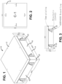
- a seat unit 10 for use in the system is shown in Figures 1-3 .
- the seat 10 includes a generally square upper surface 12 and four side walls extending downward from the four sides of the upper surface 12 to a bottom surface 14.
- a first side wall 16 and a second side wall 18 are shown in Figure 1 .
- a plurality of legs 20 extend downward from the bottom surface 14.
- the legs 20 are generally positioned proximate the corners of the bottom surface 14.
- the legs 20 are generally cylindrical, however, they can be in a variety of different shapes.
- the seat unit 10 is shown in Figures 1-3 without a seat cushion.
- a seat cushion can be seen in Figures 20 and 22-23 .
- the seat 10 includes a set of first connector components 22 on the first side wall 16 and another set of connector components 22 on the second side wall 16.
- the seat 10 can also include a set of first connector components 22 on a third side wall (opposing the first side wall 16).
- Each of the connector components 22 in a set are spaced from each other.
- the first connector components 22 are brackets that cooperate with second connector components on an arm unit or back unit.
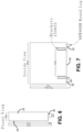
- FIGS 4-7 show a back unit (or simply "back") 24 that can be used with the seat unit 10.
- the back 10 is generally rectangular having an interior side 26 (i.e., a side that would form a back surface of any chair or couch in a seating system, albeit supporting a back cushion), an exterior side 28, a top wall 30, a first side wall 32 and a second side wall 34.
- the back 24 also includes a bottom wall 36 and legs 38 extending downward from the bottom wall 36.
- the interior side of the back also includes a set of second connector components 40.
- Each of the set of second connector components 40 are spaced out from each other to match the set of first connector components on the second side wall 18 of the seat 10.
- the first connector components 22 and the second connector components 40 are designed to fit together to securely connect the back 24 to the seat 10.
- one of the connector components is in the form of a rail having a generally rectangular cross-sectional shape
- the other component is a slider or bracket having a squared-off, generally C-shaped cross-sectional shape sized to slidingly fit over the rectangular cross-section of the rail.
- the first and second connector components 22, 40 are shown (without a seat or back unit) in Figures 26A-26C .
- Each connector component 22, 40 includes openings 74 to enable the connector to be secured to the seat or back (or arm as described below) with screws, nails or bolts, etc.
- the second connector component 40 is sized and designed to fit in an opening (having the generally C-shaped cross-sectional shape) at the top of the first connector component 22 and slide downward.
- the first connector component 22 includes a bottom wall 76 to stop the second connector component 40.
- the top of the first connector component 22 is slightly wider than the bottom of the component, which causes the sides of the component to angle slightly toward each other (from top to bottom).
- the second connector component 40 also has a slightly wider top (albeit smaller than that of the first connector component) than the bottom of the second connector component 40. Again, this causes the sides of the second connector component to angle slightly toward each other (from top to bottom).
- the angled sides of the components 22, 40 provide for a snug, secure fit when connected to each other while enabling the second component 40 to be easily removed when disassembling the system 10.
- first or second connector components can be fitted with bearings to further facilitate the slide-ability of the bracket with respect to the rail.
- first and second connector components of the present system can be similar to the components of a drawer slide bracket or similar structures.
- first connector components 22 on the seat 10 are preferably the rail structures and the second connector components 40 on the back 24 are the C-shaped brackets that fit over the rails. However, these can be reversed if desired.
- Figures 8-12 show an arm unit (or just “arm") 42 for use in the system.
- the arm 42 includes an exterior side 44, an interior side 46 and a top wall 48.
- the arm 42 also includes a bottom wall 50 and legs 52 extending downward from the bottom wall 50.
- the arm 42 also includes second connector components for connecting to the first connector components 22 on the seat 10.
- the arm 42 has two sets of staggered second connector components 40A and 40B.
- the first set of second connector components 40A allows for connecting the arm 42 to the seat 10 in a first position
- the second set of second connector components 40B allows for connecting the arm 42 to the seat 10 in a second position different than the first position. Additional sets of second connectors can be added as desired for additional positions (or to accommodate different sized or shaped seats).
- the back unit 24 can be similarly modified to include additional second connector components
- the seat 10 can be similarly modified to include additional first connector components.
- a seat 10 can be connected to a back unit 24 and one or more arm units 42 to form a chair.
- two or more seat units 10 can be connected together.
- the multiple seats 10, along with additional back units 24 and arm units 42 can form a sectional sofa or couch having a variety of configurations.
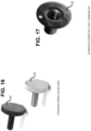
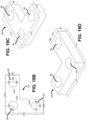
- the present system includes a connection plate 54, as illustrated in Figures 13-19 , for connecting a first seat 10 to a second seat 10.
- the connection plate 54 is generally rectangular and includes a first aperture 56 proximate a first end and a second aperture 58 proximate a second end.
- Screws 60 can be used to secure the connection plate 54 to the top surface 12 of the first seat 10 and the top surface 12 the second seat 10 as shown in Figure 18 (alternatively, the connection plate could be secured to the bottom surfaces 14 of each seat).
- the seat 10 can include a nut 62 (as shown in Figure 17 ) or similar structure for receiving the screw 60. Additionally, other similar structure can be used to secure the connector plate 54 to the seats 10.
- an L-shaped connection plate 64 can be used to connect three seats 10 together in similar configuration (e.g., Figure 19A ).
- the L-shaped connection plate 64 includes a third aperture 66 proximate the bend in the plate between the first and second apertures 58 and 56. Each aperture in the L-shaped connection plate 64 is used to secure the connection plate 64 to one of three seat components 10.
- each seat can be provided a cushion 68 which will cover and hide the connection plate 54.
- a seat 10 with a seat cushion 68 is shown in Figures 20A and 20B.
- Figure 20B shows the fabric around the seat 12 having cutouts 78.
- the cutouts 78 facilitate removal of the fabric (e.g., for replacement or cleaning) without requiring first removing the first connector components 22.
- the back and arm can include similar cutouts.
- Figure 21 shows a back unit 24 and a seat unit 10 slightly separated from the back unit 24.
- the first connector components 22 on the seat unit 10 are aligned with the second connector units 40 on the back unit 24.
- Simply lifting the back unit 24 so that the bottom of the second connector components 40 slide over the top of the first connector components 22 secures the back unit 24 to the seat unit 10.
- a similar procedure is used to secure the arm unit 42 to the seat unit 10.
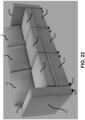
- Figure 22 shows one combination of the components of the seating system configured as a couch.
- the seat cushion 68, the couch also includes back cushions 70.
- the cushions can be loose, or alternatively, secured to the seat or back units by hook and loop material, snaps or other similar means.
- Figure 23 shows an L-shaped configuration of the seating system. Additionally, seat units 72 without connector components can be utilized in the system. Instead of legs, these units can be provided with rollers to easily move them around.
- each seat unit 10 includes a suction device 100 connected to the bottom surface of one or more of the legs 20 of the seat 10.
- the suction device 100 adheres to the floor and prevents the seat 10 from moving with respect to other seats 10 in the system.
- the other connector components described above - e.g., the first connector components 22 and the second connector components 40 - can be used with the system to connect the backs 24 and arms 24 to the seat 10.
- the suction device 100 can be used with one or more of the legs 38, 52 extending from the backs 24 and arms 42 that are connected to the seats 10.
- the suction device 100 is a circular disk having a plurality of channels 102, 104, 106 in concentric circles about the lower surface of the disk.
- the disk 100 can be formed from rubber or other similar material, and can be connected to the lower surface of the leg 20 with an adhesive on an upper surface of the disk.
- the disk is approximately 3-5 millimeters thick.
- the channels 102, 104, 106 provide a suction effect when placed on the floor, that, along with a coefficient of friction of the rubber material, keep the leg (and therefore the seat, arm or back) in place.
- FIG. 1 Another embodiment of the back and/or arm, is in the form of a corner back unit 108, 110 having an angled side wall 112, 114 (i.e., at an angle other than 90 degrees) as shown in Figures 30 and 31 .
- the angled side walls 112, 114 cooperate to form a corner seat 116 of a sectional system 118 like that shown in Figure 32 .
Landscapes
- Health & Medical Sciences (AREA)
- General Health & Medical Sciences (AREA)
- Nursing (AREA)
- Life Sciences & Earth Sciences (AREA)
- Engineering & Computer Science (AREA)
- Wood Science & Technology (AREA)
- Seats For Vehicles (AREA)
- Chair Legs, Seat Parts, And Backrests (AREA)
Applications Claiming Priority (2)
| Application Number | Priority Date | Filing Date | Title |
|---|---|---|---|
| US17/460,846 US11633046B2 (en) | 2021-08-30 | 2021-08-30 | Sectional seating system |
| US17/698,557 US11839305B2 (en) | 2021-08-30 | 2022-03-18 | Sectional seating with connectors and suction holding |
Publications (3)
| Publication Number | Publication Date |
|---|---|
| EP4166043A1 true EP4166043A1 (fr) | 2023-04-19 |
| EP4166043C0 EP4166043C0 (fr) | 2024-07-24 |
| EP4166043B1 EP4166043B1 (fr) | 2024-07-24 |
Family
ID=83059226
Family Applications (1)
| Application Number | Title | Priority Date | Filing Date |
|---|---|---|---|
| EP22191844.4A Active EP4166043B1 (fr) | 2021-08-30 | 2022-08-24 | Système d'assise modulaire |
Country Status (3)
| Country | Link |
|---|---|
| US (2) | US11839305B2 (fr) |
| EP (1) | EP4166043B1 (fr) |
| CA (1) | CA3153287A1 (fr) |
Families Citing this family (3)
| Publication number | Priority date | Publication date | Assignee | Title |
|---|---|---|---|---|
| US12484702B2 (en) * | 2019-11-15 | 2025-12-02 | Ryan Lawson | Article of furniture |
| USD1078322S1 (en) * | 2025-04-16 | 2025-06-10 | Always Outdoor Furniture CO., Ltd. | Sofa |
| USD1078305S1 (en) * | 2025-04-16 | 2025-06-10 | Always Outdoor Furniture CO., Ltd. | Sofa |
Citations (2)
| Publication number | Priority date | Publication date | Assignee | Title |
|---|---|---|---|---|
| JPS57172555U (fr) * | 1981-04-27 | 1982-10-30 | ||
| NL1038980C2 (nl) * | 2011-08-02 | 2013-02-05 | Gerardus Arnoldus Fransiscus Liebregts | Set welke een zitelement omvat. |
Family Cites Families (23)
| Publication number | Priority date | Publication date | Assignee | Title |
|---|---|---|---|---|
| US3973800A (en) | 1975-08-15 | 1976-08-10 | Allan Sheldon Kogan | Modular furniture units |
| US5000512A (en) | 1989-04-06 | 1991-03-19 | Laird William B | Upholstered seating units |
| FR2699058B1 (fr) | 1992-12-14 | 1996-05-24 | Mohamed Benabid | Sieges modulaires et demontables. |
| EP1106112A1 (fr) | 1999-11-30 | 2001-06-13 | Jimmy Wu | Construction de fauteuil modulaire |
| US7252339B2 (en) | 2003-09-15 | 2007-08-07 | Larry Owens | Bracket furniture components |
| ITMI20040037U1 (it) | 2004-02-04 | 2004-05-04 | Gruppo Ind Styling Meccanis | Bracciolo per divano comprendente mezzi di fissaggio all'intelaiatura del divano |
| US10070725B2 (en) | 2010-11-12 | 2018-09-11 | The Lovesac Company | Modular furniture assembly with dual coupling mechanisms |
| US20160174715A1 (en) | 2005-06-10 | 2016-06-23 | Sac Acquisition Llc | Modular furniture assembly with dual coupling mechanisms |
| US8783778B2 (en) | 2005-06-10 | 2014-07-22 | Sac Acquistion Llc | Mounting platform for modular furniture assembly |
| US7213885B2 (en) | 2005-06-10 | 2007-05-08 | Sac Acquistion Llc | Modular furniture assembly |
| BR102014014055A2 (pt) | 2014-06-10 | 2016-01-05 | Danilo Lunardi Scussolino | aperfeiçoamentos introduzidos em sistema de fornecimento e montagem de móveis em geral |
| US9668581B1 (en) | 2014-10-15 | 2017-06-06 | Prominence Furniture & Finishing, Inc. | Knockdown sofa |
| US10123621B2 (en) * | 2015-11-19 | 2018-11-13 | The Lovesac Company | Furniture system recliner assembly with sled rails |
| US20170367486A1 (en) | 2016-06-24 | 2017-12-28 | Sac Acquisition Llc | Modular Furniture Assembly Corner Seating System |
| US20180360219A1 (en) * | 2017-06-16 | 2018-12-20 | Phyllis Renee Gant | Child's hair care chair |
| US10736470B2 (en) * | 2017-07-28 | 2020-08-11 | Medline Industries, Inc. | Modular seating apparatus and corresponding systems |
| US20200262696A1 (en) | 2019-02-15 | 2020-08-20 | The Lovesac Company | Molded manufacturing for modular furniture |
| US20210068547A1 (en) | 2019-09-06 | 2021-03-11 | Overman International Corporation | Toolless Assembly Method for Upholstered Furniture |
| CA3163165A1 (fr) * | 2019-12-30 | 2021-07-08 | Robert Mccreary | Meuble modulaire a ensemble de support d'etagere |
| CN212117653U (zh) | 2020-03-19 | 2020-12-11 | 锐迈机械科技(吴江)有限公司 | 一种沙发扶手连接结构及沙发组件 |
| US20210330134A1 (en) * | 2020-04-28 | 2021-10-28 | Lerrlyn Nelson | In-Case Portable Travel Shower Chair |
| US12070131B2 (en) | 2020-06-30 | 2024-08-27 | The Lovesac Company | Reconfigurable modular furniture assembly with overlapping geometry |
| CN216651842U (zh) | 2022-01-27 | 2022-06-03 | 安徽省武狄智能家居科技有限公司 | 一种可拆卸式沙发 |
-
2022
- 2022-03-18 US US17/698,557 patent/US11839305B2/en active Active
- 2022-03-24 CA CA3153287A patent/CA3153287A1/fr active Pending
- 2022-08-24 EP EP22191844.4A patent/EP4166043B1/fr active Active
-
2023
- 2023-10-11 US US18/485,081 patent/US12185837B2/en active Active
Patent Citations (2)
| Publication number | Priority date | Publication date | Assignee | Title |
|---|---|---|---|---|
| JPS57172555U (fr) * | 1981-04-27 | 1982-10-30 | ||
| NL1038980C2 (nl) * | 2011-08-02 | 2013-02-05 | Gerardus Arnoldus Fransiscus Liebregts | Set welke een zitelement omvat. |
Also Published As
| Publication number | Publication date |
|---|---|
| CA3153287A1 (fr) | 2023-02-28 |
| US20240108146A1 (en) | 2024-04-04 |
| EP4166043C0 (fr) | 2024-07-24 |
| US12185837B2 (en) | 2025-01-07 |
| US20230062614A1 (en) | 2023-03-02 |
| EP4166043B1 (fr) | 2024-07-24 |
| US11839305B2 (en) | 2023-12-12 |
Similar Documents
| Publication | Publication Date | Title |
|---|---|---|
| EP4166043A1 (fr) | Système d'assise modulaire | |
| US11633046B2 (en) | Sectional seating system | |
| US9968187B2 (en) | Modular furniture unit having power distribution | |
| US8579127B2 (en) | Closet organizer shelving system | |
| US7469512B2 (en) | Fabricated wall system | |
| US6550195B1 (en) | Floor system | |
| US9755385B1 (en) | Electrical receptacle assembly | |
| US9247812B2 (en) | Table privacy panel | |
| US20120304900A1 (en) | Office desking system | |
| US8943624B1 (en) | Captains bed having integrated shelving and slideout features | |
| EP0312369A2 (fr) | Meuble | |
| US20150023729A1 (en) | Office furniture system | |
| HK1220593A1 (zh) | 悬椅和模块化家具套件 | |
| US20060132003A1 (en) | Modular furniture system | |
| US8550015B2 (en) | Modular table system | |
| US20110298256A1 (en) | Floor track for seating system | |
| US9585472B2 (en) | Adaptive furniture | |
| US5447386A (en) | System for locking furniture panels | |
| US20180192767A1 (en) | Slidable furniture with in-wall mounting system | |
| JP2012135373A (ja) | カウンターにおけるハイユニットと可動仕切パネルの固定装置 | |
| JP2022068537A (ja) | 連結構造 | |
| US20250221525A1 (en) | Modular tables with attached seat(s) | |
| US12433408B2 (en) | Furniture having spans supported by downwardly flaring posts | |
| JP3033939U (ja) | 机 | |
| GB2596348A (en) | Apparatus for mounting on to a seat |
Legal Events
| Date | Code | Title | Description |
|---|---|---|---|
| PUAI | Public reference made under article 153(3) epc to a published international application that has entered the european phase |
Free format text: ORIGINAL CODE: 0009012 |
|
| STAA | Information on the status of an ep patent application or granted ep patent |
Free format text: STATUS: THE APPLICATION HAS BEEN PUBLISHED |
|
| AK | Designated contracting states |
Kind code of ref document: A1 Designated state(s): AL AT BE BG CH CY CZ DE DK EE ES FI FR GB GR HR HU IE IS IT LI LT LU LV MC MK MT NL NO PL PT RO RS SE SI SK SM TR |
|
| STAA | Information on the status of an ep patent application or granted ep patent |
Free format text: STATUS: REQUEST FOR EXAMINATION WAS MADE |
|
| 17P | Request for examination filed |
Effective date: 20231018 |
|
| RBV | Designated contracting states (corrected) |
Designated state(s): AL AT BE BG CH CY CZ DE DK EE ES FI FR GB GR HR HU IE IS IT LI LT LU LV MC MK MT NL NO PL PT RO RS SE SI SK SM TR |
|
| GRAP | Despatch of communication of intention to grant a patent |
Free format text: ORIGINAL CODE: EPIDOSNIGR1 |
|
| STAA | Information on the status of an ep patent application or granted ep patent |
Free format text: STATUS: GRANT OF PATENT IS INTENDED |
|
| INTG | Intention to grant announced |
Effective date: 20240220 |
|
| GRAS | Grant fee paid |
Free format text: ORIGINAL CODE: EPIDOSNIGR3 |
|
| GRAA | (expected) grant |
Free format text: ORIGINAL CODE: 0009210 |
|
| STAA | Information on the status of an ep patent application or granted ep patent |
Free format text: STATUS: THE PATENT HAS BEEN GRANTED |
|
| AK | Designated contracting states |
Kind code of ref document: B1 Designated state(s): AL AT BE BG CH CY CZ DE DK EE ES FI FR GB GR HR HU IE IS IT LI LT LU LV MC MK MT NL NO PL PT RO RS SE SI SK SM TR |
|
| REG | Reference to a national code |
Ref country code: GB Ref legal event code: FG4D |
|
| REG | Reference to a national code |
Ref country code: CH Ref legal event code: EP |
|
| REG | Reference to a national code |
Ref country code: DE Ref legal event code: R096 Ref document number: 602022004762 Country of ref document: DE |
|
| REG | Reference to a national code |
Ref country code: IE Ref legal event code: FG4D |
|
| U01 | Request for unitary effect filed |
Effective date: 20240826 |
|
| U07 | Unitary effect registered |
Designated state(s): AT BE BG DE DK EE FI FR IT LT LU LV MT NL PT RO SE SI Effective date: 20240903 |
|
| U20 | Renewal fee for the european patent with unitary effect paid |
Year of fee payment: 3 Effective date: 20240923 |
|
| PG25 | Lapsed in a contracting state [announced via postgrant information from national office to epo] |
Ref country code: NO Free format text: LAPSE BECAUSE OF FAILURE TO SUBMIT A TRANSLATION OF THE DESCRIPTION OR TO PAY THE FEE WITHIN THE PRESCRIBED TIME-LIMIT Effective date: 20241024 |
|
| PG25 | Lapsed in a contracting state [announced via postgrant information from national office to epo] |
Ref country code: GR Free format text: LAPSE BECAUSE OF FAILURE TO SUBMIT A TRANSLATION OF THE DESCRIPTION OR TO PAY THE FEE WITHIN THE PRESCRIBED TIME-LIMIT Effective date: 20241025 Ref country code: PL Free format text: LAPSE BECAUSE OF FAILURE TO SUBMIT A TRANSLATION OF THE DESCRIPTION OR TO PAY THE FEE WITHIN THE PRESCRIBED TIME-LIMIT Effective date: 20240724 |
|
| PG25 | Lapsed in a contracting state [announced via postgrant information from national office to epo] |
Ref country code: IS Free format text: LAPSE BECAUSE OF FAILURE TO SUBMIT A TRANSLATION OF THE DESCRIPTION OR TO PAY THE FEE WITHIN THE PRESCRIBED TIME-LIMIT Effective date: 20241124 |
|
| PG25 | Lapsed in a contracting state [announced via postgrant information from national office to epo] |
Ref country code: HR Free format text: LAPSE BECAUSE OF FAILURE TO SUBMIT A TRANSLATION OF THE DESCRIPTION OR TO PAY THE FEE WITHIN THE PRESCRIBED TIME-LIMIT Effective date: 20240724 |
|
| PG25 | Lapsed in a contracting state [announced via postgrant information from national office to epo] |
Ref country code: ES Free format text: LAPSE BECAUSE OF FAILURE TO SUBMIT A TRANSLATION OF THE DESCRIPTION OR TO PAY THE FEE WITHIN THE PRESCRIBED TIME-LIMIT Effective date: 20240724 Ref country code: RS Free format text: LAPSE BECAUSE OF FAILURE TO SUBMIT A TRANSLATION OF THE DESCRIPTION OR TO PAY THE FEE WITHIN THE PRESCRIBED TIME-LIMIT Effective date: 20241024 |
|
| PG25 | Lapsed in a contracting state [announced via postgrant information from national office to epo] |
Ref country code: RS Free format text: LAPSE BECAUSE OF FAILURE TO SUBMIT A TRANSLATION OF THE DESCRIPTION OR TO PAY THE FEE WITHIN THE PRESCRIBED TIME-LIMIT Effective date: 20241024 Ref country code: PL Free format text: LAPSE BECAUSE OF FAILURE TO SUBMIT A TRANSLATION OF THE DESCRIPTION OR TO PAY THE FEE WITHIN THE PRESCRIBED TIME-LIMIT Effective date: 20240724 Ref country code: NO Free format text: LAPSE BECAUSE OF FAILURE TO SUBMIT A TRANSLATION OF THE DESCRIPTION OR TO PAY THE FEE WITHIN THE PRESCRIBED TIME-LIMIT Effective date: 20241024 Ref country code: IS Free format text: LAPSE BECAUSE OF FAILURE TO SUBMIT A TRANSLATION OF THE DESCRIPTION OR TO PAY THE FEE WITHIN THE PRESCRIBED TIME-LIMIT Effective date: 20241124 Ref country code: HR Free format text: LAPSE BECAUSE OF FAILURE TO SUBMIT A TRANSLATION OF THE DESCRIPTION OR TO PAY THE FEE WITHIN THE PRESCRIBED TIME-LIMIT Effective date: 20240724 Ref country code: GR Free format text: LAPSE BECAUSE OF FAILURE TO SUBMIT A TRANSLATION OF THE DESCRIPTION OR TO PAY THE FEE WITHIN THE PRESCRIBED TIME-LIMIT Effective date: 20241025 Ref country code: ES Free format text: LAPSE BECAUSE OF FAILURE TO SUBMIT A TRANSLATION OF THE DESCRIPTION OR TO PAY THE FEE WITHIN THE PRESCRIBED TIME-LIMIT Effective date: 20240724 |
|
| PG25 | Lapsed in a contracting state [announced via postgrant information from national office to epo] |
Ref country code: SM Free format text: LAPSE BECAUSE OF FAILURE TO SUBMIT A TRANSLATION OF THE DESCRIPTION OR TO PAY THE FEE WITHIN THE PRESCRIBED TIME-LIMIT Effective date: 20240724 |
|
| PG25 | Lapsed in a contracting state [announced via postgrant information from national office to epo] |
Ref country code: MC Free format text: LAPSE BECAUSE OF FAILURE TO SUBMIT A TRANSLATION OF THE DESCRIPTION OR TO PAY THE FEE WITHIN THE PRESCRIBED TIME-LIMIT Effective date: 20240724 |
|
| PG25 | Lapsed in a contracting state [announced via postgrant information from national office to epo] |
Ref country code: CZ Free format text: LAPSE BECAUSE OF FAILURE TO SUBMIT A TRANSLATION OF THE DESCRIPTION OR TO PAY THE FEE WITHIN THE PRESCRIBED TIME-LIMIT Effective date: 20240724 |
|
| PG25 | Lapsed in a contracting state [announced via postgrant information from national office to epo] |
Ref country code: SK Free format text: LAPSE BECAUSE OF FAILURE TO SUBMIT A TRANSLATION OF THE DESCRIPTION OR TO PAY THE FEE WITHIN THE PRESCRIBED TIME-LIMIT Effective date: 20240724 |
|
| PLBE | No opposition filed within time limit |
Free format text: ORIGINAL CODE: 0009261 |
|
| STAA | Information on the status of an ep patent application or granted ep patent |
Free format text: STATUS: NO OPPOSITION FILED WITHIN TIME LIMIT |
|
| 26N | No opposition filed |
Effective date: 20250425 |
|
| PG25 | Lapsed in a contracting state [announced via postgrant information from national office to epo] |
Ref country code: IE Free format text: LAPSE BECAUSE OF NON-PAYMENT OF DUE FEES Effective date: 20240824 |
|
| PGFP | Annual fee paid to national office [announced via postgrant information from national office to epo] |
Ref country code: TR Payment date: 20251223 Year of fee payment: 4 |
|
| U21 | Renewal fee for the european patent with unitary effect paid with additional fee |
Year of fee payment: 4 Effective date: 20251217 |
|
| PG25 | Lapsed in a contracting state [announced via postgrant information from national office to epo] |
Ref country code: CY Free format text: LAPSE BECAUSE OF FAILURE TO SUBMIT A TRANSLATION OF THE DESCRIPTION OR TO PAY THE FEE WITHIN THE PRESCRIBED TIME-LIMIT; INVALID AB INITIO Effective date: 20220824 |
|
| PG25 | Lapsed in a contracting state [announced via postgrant information from national office to epo] |
Ref country code: HU Free format text: LAPSE BECAUSE OF FAILURE TO SUBMIT A TRANSLATION OF THE DESCRIPTION OR TO PAY THE FEE WITHIN THE PRESCRIBED TIME-LIMIT; INVALID AB INITIO Effective date: 20220824 |
|
| REG | Reference to a national code |
Ref country code: CH Ref legal event code: H13 Free format text: ST27 STATUS EVENT CODE: U-0-0-H10-H13 (AS PROVIDED BY THE NATIONAL OFFICE) Effective date: 20260324 |
|
| PG25 | Lapsed in a contracting state [announced via postgrant information from national office to epo] |
Ref country code: CH Free format text: LAPSE BECAUSE OF NON-PAYMENT OF DUE FEES Effective date: 20250831 |