EP4166078A1 - Vakuumkissen und entsprechendes system - Google Patents
Vakuumkissen und entsprechendes system Download PDFInfo
- Publication number
- EP4166078A1 EP4166078A1 EP21211975.4A EP21211975A EP4166078A1 EP 4166078 A1 EP4166078 A1 EP 4166078A1 EP 21211975 A EP21211975 A EP 21211975A EP 4166078 A1 EP4166078 A1 EP 4166078A1
- Authority
- EP
- European Patent Office
- Prior art keywords
- vacuum pad
- vacuum
- active area
- fluid
- outlet tube
- Prior art date
- Legal status (The legal status is an assumption and is not a legal conclusion. Google has not performed a legal analysis and makes no representation as to the accuracy of the status listed.)
- Withdrawn
Links
Images





Classifications
-
- A—HUMAN NECESSITIES
- A61—MEDICAL OR VETERINARY SCIENCE; HYGIENE
- A61B—DIAGNOSIS; SURGERY; IDENTIFICATION
- A61B5/00—Measuring for diagnostic purposes; Identification of persons
- A61B5/15—Devices for taking samples of blood
- A61B5/150007—Details
- A61B5/150015—Source of blood
- A61B5/150045—Source of blood for blood from vagina, placenta, colon or mouth
-
- A—HUMAN NECESSITIES
- A61—MEDICAL OR VETERINARY SCIENCE; HYGIENE
- A61G—TRANSPORT, PERSONAL CONVEYANCES, OR ACCOMMODATION SPECIALLY ADAPTED FOR PATIENTS OR DISABLED PERSONS; OPERATING TABLES OR CHAIRS; CHAIRS FOR DENTISTRY; FUNERAL DEVICES
- A61G13/00—Operating tables; Auxiliary appliances therefor
- A61G13/10—Parts, details or accessories
- A61G13/102—Fluid drainage means for collecting bodily fluids from the operating table, e.g. for blood, urine
-
- A—HUMAN NECESSITIES
- A61—MEDICAL OR VETERINARY SCIENCE; HYGIENE
- A61B—DIAGNOSIS; SURGERY; IDENTIFICATION
- A61B5/00—Measuring for diagnostic purposes; Identification of persons
- A61B5/15—Devices for taking samples of blood
- A61B5/150007—Details
- A61B5/150053—Details for enhanced collection of blood or interstitial fluid at the sample site, e.g. by applying compression, heat, vibration, ultrasound, suction or vacuum to tissue; for reduction of pain or discomfort; Skin piercing elements, e.g. blades, needles, lancets or canulas, with adjustable piercing speed
- A61B5/150061—Means for enhancing collection
- A61B5/150099—Means for enhancing collection by negative pressure, other than vacuum extraction into a syringe by pulling on the piston rod or into pre-evacuated tubes
-
- A—HUMAN NECESSITIES
- A61—MEDICAL OR VETERINARY SCIENCE; HYGIENE
- A61B—DIAGNOSIS; SURGERY; IDENTIFICATION
- A61B5/00—Measuring for diagnostic purposes; Identification of persons
- A61B5/15—Devices for taking samples of blood
- A61B5/150007—Details
- A61B5/150206—Construction or design features not otherwise provided for; manufacturing or production; packages; sterilisation of piercing element, piercing device or sampling device
- A61B5/150229—Pumps for assisting the blood sampling
-
- A—HUMAN NECESSITIES
- A61—MEDICAL OR VETERINARY SCIENCE; HYGIENE
- A61G—TRANSPORT, PERSONAL CONVEYANCES, OR ACCOMMODATION SPECIALLY ADAPTED FOR PATIENTS OR DISABLED PERSONS; OPERATING TABLES OR CHAIRS; CHAIRS FOR DENTISTRY; FUNERAL DEVICES
- A61G13/00—Operating tables; Auxiliary appliances therefor
- A61G13/0009—Obstetrical tables or delivery beds
-
- A—HUMAN NECESSITIES
- A61—MEDICAL OR VETERINARY SCIENCE; HYGIENE
- A61M—DEVICES FOR INTRODUCING MEDIA INTO, OR ONTO, THE BODY; DEVICES FOR TRANSDUCING BODY MEDIA OR FOR TAKING MEDIA FROM THE BODY; DEVICES FOR PRODUCING OR ENDING SLEEP OR STUPOR
- A61M1/00—Suction or pumping devices for medical purposes; Devices for carrying-off, for treatment of, or for carrying-over, body-liquids; Drainage systems
- A61M1/71—Suction drainage systems
- A61M1/73—Suction drainage systems comprising sensors or indicators for physical values
-
- A—HUMAN NECESSITIES
- A61—MEDICAL OR VETERINARY SCIENCE; HYGIENE
- A61B—DIAGNOSIS; SURGERY; IDENTIFICATION
- A61B5/00—Measuring for diagnostic purposes; Identification of persons
- A61B5/15—Devices for taking samples of blood
- A61B5/150007—Details
- A61B5/150366—Blood collection bags, e.g. connected to the patient by a catheter comprising means for removing a small sample of collected blood from the bag
-
- A—HUMAN NECESSITIES
- A61—MEDICAL OR VETERINARY SCIENCE; HYGIENE
- A61B—DIAGNOSIS; SURGERY; IDENTIFICATION
- A61B5/00—Measuring for diagnostic purposes; Identification of persons
- A61B5/15—Devices for taking samples of blood
- A61B5/155—Devices specially adapted for continuous or multiple sampling, e.g. at predetermined intervals
-
- A—HUMAN NECESSITIES
- A61—MEDICAL OR VETERINARY SCIENCE; HYGIENE
- A61G—TRANSPORT, PERSONAL CONVEYANCES, OR ACCOMMODATION SPECIALLY ADAPTED FOR PATIENTS OR DISABLED PERSONS; OPERATING TABLES OR CHAIRS; CHAIRS FOR DENTISTRY; FUNERAL DEVICES
- A61G2203/00—General characteristics of devices
- A61G2203/30—General characteristics of devices characterised by sensor means
Definitions
- the present disclosure relates to a device for collecting and monitoring fluid loss in a medical procedure, such as a mother's blood loss during a caesarean delivery.
- a medical procedure such as a mother's blood loss during a caesarean delivery.
- the present disclosure relates to a vacuum pad and related system.
- a human or animal patient may experience fluid loss in a variety of situations, particularly in surgical procedures. For instance, some women experience moderate to severe bleeding from the uterus during a Cesarean delivery ("C-section"). While a certain amount of bleeding is normal and safe, (e.g., an average C-section is associated with about four cups of blood loss), excess blood loss can be dangerous. Other fluid losses that may need to be addressed included losses of amniotic fluid, vaginal discharge, etc. To complicate matters, the patient is often covered by a surgical drape, which may limit the surgeon's ability to monitor fluid loss visually. To address these issues, the present disclosure relates to a device for collecting and monitoring fluid loss in a medical procedure.
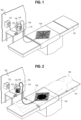
- FIGS. 1-2 show an example of a vacuum fluid collection system 102.
- the system 102 generally includes a vacuum pad 104 being utilized for the collection of blood 103 or another fluid from a patient.
- the vacuum pad 104 and vacuum system 102 are described herein as being designed for use in a medical setting. However, it is recognized that these devices may additionally or alternatively be used in other contexts, including settings outside of medical applications.
- the vacuum pad 104 and/or the remainder of the vacuum system 102 may be used for any suitable medical procedure, particularly where the collection and monitoring of a body fluid originating from a patient 108 are desired.
- this disclosure focuses on the collection and monitoring of blood 106 from a surgical table 101 during a C-section (e.g., FIG. 2 ). Since some women experience moderate to severe bleeding from the uterus during a C-section, it is desirable to collect the blood as it comes from the woman's body and to remove it from the top surface of the surgical table. Further, since excess blood loss can be dangerous, it is desirable to monitor the total amount of blood lost during the procedure as well as the real-time rate of loss. The devices and methods described herein accomplish both of these features.
- the vacuum system 102 may generally include the vacuum pad 104, which is configured to be placed on the surgical table 101 and beneath a patient's body 108. As discussed in greater detail below, the vacuum pad 104 may be configured for the collection of blood (or another fluid) from the patient, and may direct that blood to a vacuum hose 110 to move the blood away from the surgical table 101. In other embodiments, the vacuum pad 104 may be a portion of the surgical table 101 (e.g., providing a portion of the support for the table's top surface).
- the vacuum hose 110 may ultimately be in fluid communication with a vacuum source 112.
- Any suitable vacuum source 112 may be used.
- the vacuum source 112 may be a common vacuum-supply system available in many hospital settings that comply with NFPA99 design standards, where a pump within a dedicated room of the building provides a vacuum to each (or many) of the hospital rooms via vacuum plumbing.
- a portable, stand-alone vacuum source 112 may be used instead.
- a canister 114 may be located between the vacuum pad 104 and the vacuum source 112, as shown.
- the canister 114 may be configured for collecting and storing the blood as it is pulled from the vacuum pad 104.
- an inlet 116 to the canister 114, and also a vacuum outlet 118 may be located near a top portion of the canister 114.
- blood enters from the top of the canister 114 via the inlet 116 it falls to the bottom of the canister 114 where it remains collected and stored for the duration of the procedure.
- the total blood loss from the patient 108 may directly correlate with the volume and/or mass of blood collected within the canister 114. This may be monitored visually (e.g., with graduations on a transparent surface of the canister 114) and/or electrically.
- a sensor 120 may be included with the canister 114 for detecting a characteristic of the blood or other fluid within the canister 114.
- the sensor 120 may be a fluid level sensor that is fixed to the canister 114.
- the sensor 120 may alternatively or additionally be a weight/mass scale placed beneath the canister 114 such that the mass of liquid within the canister 114 is monitored. Any other suitable sensor can be alternatively or additionally included.
- a computer of the monitor/alarm system When coupled within a monitor/alarm system, a computer of the monitor/alarm system may be electrically connected to the sensor 120 such that the monitor/alarm system evaluates the blood collection and compare such collection to particular quantity and/or rate thresholds. If a preset threshold is met, the monitor/alarm system may provide an alert, such as by sounding a visual or audible alarm or by otherwise notifying the medical professional(s) of potential problem.
- the monitor/alarm system may additionally or alternatively include data collection and evaluation capabilities such that the procedure can be evaluated after the fact.
- the canister 114 may include one or more sensors or other devices for detecting other characteristics of the blood or other fluid.
- the system may be capable of detecting and monitoring a visual characteristic (e.g., color, a viscosity of the fluid, a conductivity of the fluid, temperature of the fluid, a salinity of the fluid, an acidity of the fluid, or any other characteristic where evaluation is desirable.
- a visual characteristic e.g., color, a viscosity of the fluid, a conductivity of the fluid, temperature of the fluid, a salinity of the fluid, an acidity of the fluid, or any other characteristic where evaluation is desirable.
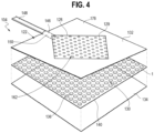
- FIGS. 3-4 show the vacuum pad 104 in isolation.
- the upper surface 122 may face the patient body, and the lower surface 124 may face opposite the upper surface 122 (e.g., such that the lower surface 124 may contact a surgery table).
- An active area 128 of the vacuum pad 104 may be surrounded by a boundary portion 176 (which is discussed in more detail below), where the active area 128 is generally sized and shaped for placement beneath a target area of the patient's body for fluid collection.
- the vacuum pad 104 may be outfitted with drainage capability (and/or other fluid-control capability, such as absorption) for removing or otherwise addressing fluid that would otherwise collect on the vacuum pad's upper surface 122.
- the upper surface 122 of the vacuum pad 104 may include one or more holes 129 that extend to a chamber or interior space 130 within the vacuum pad 104.
- the interior space 130 may be defined between a top layer 132 and a bottom layer 134 (see FIG. 4 ). When blood collects on the upper surface 122, it flows through these holes 129 and into the interior space 130. This flow may be caused or assisted via the vacuum system discussed above.
- the materials forming the top layer 132 and/or the bottom layer 134 may be any suitable material(s).
- the top layer 132 may be formed of a hydrophobic material to ensure the vacuum pad 104 does not absorb any liquid, which may be advantageous for facilitating flow of the fluid towards the center of the vacuum pad 104.
- the bottom layer 134 may include a texturized, non-slip material on its bottom surface, which may ensure the vacuum pad 104 maintains proper placement relative to the surgical table, for example.
- the top layer 132 and the bottom layer 134 may be separated via one or more spacers 136.
- spacers 136 may be included between the top layer 132 and the bottom layer 134 such that the interior space 130 is formed with a plurality of fluid flowpaths or channels that generally extend around and between the spacers 136.
- the spacers 136 may be formed with any suitable structure.
- the spacers 136 may be air pockets surrounded by a membrane 140 (e.g., of a polymer) or another sealed structure.
- the spacers 136 are optionally secured to one another and/or to at least one of the top layer 132 and the bottom layer 134 of the vacuum pad 104.
- these air pockets 142 may be coupled together via one or more securement structures to form a spacer pad, in this case in a manner resembling (or identical to) a sheet of common bubble wrap.
- the spacers 136 include the membrane layer 140, it is possible for the membrane layer 140 to act as the lower-most layer of the vacuum pad 104 (meaning the bottom layer 134 shown in FIG. 4 , or alternatively the top layer 132, may be absent), but this is not required.
- spacers 136 with resilient air pockets may be advantageous since such spacers may provide cushioning to the patient due to the compressibility of the air within, particularly when patient's body weight will at least partially rest upon the vacuum pad 104. While the spacers 136 may compress a certain amount, the spacers 136 will ideally retain their shape enough such that the channels 138 between the spacers 136 are not sealed off. However, since a relatively large active area 128 with many spacers 136 may be included, restriction or prevention of blood flow between certain adjacent spacers 136 in certain areas of the vacuum pad 104 may occur without substantially harming the overall function of the vacuum pad 104.
- spacers may be included that have a different construction.
- solid spacers formed of rubber or another compliant material may be used and may have a similar cushioning effect.
- relatively rigid spacers may be used.
- the spacers 136 may have any suitable size, shape, orientation, relative positioning (e.g., pattern), or the like such that blood flow, cushioning, and/or other characteristics are appropriate for a particular application.
- the spacers 136 may be located such that they are offset relative to the holes 129 (e.g., such that they do not block the holes 129).
- this disclosure also covers embodiments without spacers altogether, such as an embodiment where the vacuum pad 104 includes a continuous absorbent material, where one or more tubes extending through the vacuum pad 104 render the spacers unnecessary, etc.
- the interior space 130 between the upper top layer 132 and the bottom layer 134 may be in fluid communication with the vacuum source 112 via direct fluid communication.
- a hollow outlet tube 144 may have an internal portion 146 that is within the interior space 130 and an external portion 148 that is outside the interior space 130.
- the external portion 148 of the outlet tube 144 may be connectable to the vacuum hose 110 shown in FIG. 1 .
- the outlet tube 144 may include a particular interface connection 149, such as threads, an O-ring, etc. where the hose 110 may be connected in a non-leaking manner.
- outlet tube 144 may simply be replaced by an extended version of the vacuum hose
- a separate outlet tube 144 may be advantageous where it is desirable for the outlet tube 144 to be rigid, while the vacuum hose may be better suited as a flexible hose.
- rigidity for the internal portion 146 of the outlet tube 144 may be important for ensuring fluid communication at the outlet of the vacuum pad 104 is not interrupted, even when under a load (e.g., the weight of the patient).
- flexibility within the vacuum hose may be desirable such that the hose can be moved or otherwise manipulated throughout the room to avoid obstacles, stay clear of the surgery area, etc.
- the internal portion 146 of the outlet tube 144 shown in FIGS. 3-4 may include a rigid length 150 that protects the structural integrity of the outlet from the active area 128.
- a rigid length 150 that protects the structural integrity of the outlet from the active area 128.
- the structure of the internal portion of the outlet tube 144 may be substantially the same as the exterior portion of the outlet tube 144, or not.
- the internal portion 146 and the external portion 148 may simply be a cylindrical-shaped tube with a uniform (and common) exterior surface. For example, a section of 3/8" diameter plastic tubing may be used without significant modification.
- the internal portion 146 and the external portion 148 may be different.
- the internal portion 146 of the outlet tube 144 may have a matching set of openings/holes (or another permeable structure) that allow direct flow from the upper surface 122, through the holes 129, and into the outlet tube 144.
- the external portion 148 of the outlet tube 144 should remain fluidimpermeable so it does not leak.
- the outlet tube 144 terminates soon after it enters the interior space 130 in FIG. 3 , it may extend further in other embodiments, for example to roughly the center, or substantially across the active area 128, etc.
- the outlet tube 144 may have one or more bifurcations where different branches 145 go different directions within the interior space 130. If the holes 129 are arranged in a particular pattern (for reasons discussed below in more detail), the outlet tube 144 may be substantially coextensive this pattern, for example, and it may include a set of holes 131 that are generally coextensive with the holes 129. Such a design may be advantageous for providing enhanced support for the interior space 130 where fluid flow rate may be critical.
- the outlet tube 144 may include one or more openings, be formed of a porous material (e.g., a textile, a netting, etc.), or the like such that blood can flow into the outlet tube 144.
- a porous material e.g., a textile, a netting, etc.
- one or more support structures 164 may extend from a terminal end of the outlet tube 144.
- the support structure 164 may include a set of protrusions, a netted/porous sleeve, or any other suitable structure that provides structural integrity to the interior space 130 at a location adjacent to the outlet tube 144.
- Such support structures may also/alternatively be located at other places. E.g., in a manner similar to the embodiment discussed above with reference to FIGS. 5-6 , this support structure 164 may extend along a portion of, or the entirety of, a drainage pattern of the vacuum pad 104.
- the active area 128 of the vacuum pad 104 may have a variety of shapes and sizes, depending on the preferred application (e.g., C-section vs. other applications), size of the patient, strength of the vacuum source, manufacturing constraints, etc.
- the embodiments of FIGS. 1-8 each have a generally-square active area 128. While any suitable size may be used for a particular set of circumstances, the active area 128 may generally have an area of between about 3 square feet to about 0.5 square feet, such as about 1 square foot in an embodiment particularly designed for use during C-sections.
- the holes 129 may also be intentionally sized for particular fluid and vacuum characteristics.
- ideal hole diameter sizes range from about 0.020 inches to about 0.060 inches, such as about 0.040 inches.
- the holes 129 may be sized to filter out certain objects (e.g., blood clots) such that the vacuum hose remains clog-free.
- the performance of the device may be heavily influenced by the size of the active area 128, as well as the size, pattern, and number of holes 129.
- the device provided consistent, high-performing results.
- the device proved capable of handling flow rates onto the upper surface 122 of up to 500mL/min of blood without significant leakage or fluid loss. Using a 250mL/min test flow, less than 15mL leaked over the first 600mL of fluid drawn into the canister.
- edges 166 of the square may be angled relative to terminal edges 168 of the vacuum pad 104.
- angling the square in this manner may provide enhanced "catching" ability due to a more advantageous orientation relative to the surgical site and/or target area of the patient's body.
- FIG. 9 depicts a standard square that is not angled (in contrast to the device(s) of FIG. 1-8 ).
- the shape of the active area 128 may be specifically designed or selected for a particular orientation and/or placement relative to the patient, and optimal shape, orientation, and/or size may vary depending on the particular procedure to be performed, size of the operating table, vacuum strength, surgeon preference, etc.
- the size and/or shape of the active area 128 may also depend on the desired size of the holes 129. To illustrate, the active area 128 may be relatively larger while the hole size (or number of openings) may be relatively smaller, which may allow for a larger active area 128 without unduly sacrificing per-unit-area vacuum strength. The inverse may also be true: the size of the active area 128 may be relatively small, but the opening size (and/or number of holes 129) may be relatively large per unit area of the active area 128 such that a sufficient vacuum strength per-unit-area is possible.
- the arrangement of the holes 129 may also affect the performance of the vacuum pad 104 performance, and the inventors conceived of several specific hole arrangements that improve the capabilities of the device.
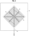
- the holes 129 may generally be arranged in a star pattern.
- the star pattern may include a central area 174 along with a set of branches 175 that each extend radially outwardly from the central area 174.
- the holes 129 are spaced apart within the branches 175 such that about 0.3 inches to about 0.5 inches of space is located between adjacent holes 129 (and a similar spacing may be used with other patterns, for example). At least one of the branches 175 may generally align with the internal portion 146 of the outlet tube 144, which may reduce internal pressure loss as the blood moves into the outlet tube 144. [Question for inventors: I understand openings are 0.020" to 0.060" in diameter, but how many are there? For example, how many openings are in each of the branches 175? Is there a particular spacing between the holes?] While the spacers 136 are generally located throughout the active area 128, in other embodiments the spacers 136 may be concentrated beneath the locations of the holes, for example.
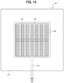
- FIG. 10 shows the holes 129 are generally placed in a grid pattern, for example, with gridlines generally parallel to the lines of the boundaries of the active area 128.
- FIG. 3-4 shows a generally uniform distribution of the holes 129. May other options are also available.
- the vacuum pad 104 may include the defined active area 128 that is at least partially surrounded by a boundary portion 176.
- the boundary portion 176 may include a construction that is substantially different than a construction of the active area 128.
- the boundary portion 176 may generally lack the channels, spacers, and/or other features included in the active area 128 since the boundary portion 176 may not be designed to drain the fluid,
- boundary portion 176 may be configured to direct the fluid towards the active area 128 in some embodiments.
- the boundary portion 176 may include a low-friction, water-repellant material to facilitate flow towards the center of the vacuum pad 104.
- the boundary portion 176 may further include a rigidity that is greater relative to a rigidity of at least the top layer of the active area 128.
- the boundary portion 176 may include a wood, rigid polymer/plastic, metal, or other material that causes the boundary portion 176 to retain its shape. This may be the case even when the boundary portion 176 is not placed on a surgical table.
- the boundary portion 176 may form a portion of an upper surface 178 of the surgical table, and it is contemplated that the top of the boundary portion 176 may include cushioning and/or other features appropriate for supporting the patient's body.
- the boundary portion 176 may have a strength and rigidity sufficient such that the vacuum pad 104 may be moved while supporting the patient's body, thus having the capability to act as a transport surface for moving the patient from one place to another.
- certain indicators and/or handles may be included to indicate where lifting force should be applied.
- the boundary portion 176 may be generally adjacent and co-planar to a separate support surface structure 180 of the surgical table 101, but this is not required.
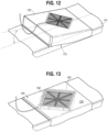
- FIG. 12 shows an embodiment where the boundary portion 176 is sloped relative to the surgical table 101.
- the slope may be caused by an angled surface 172 located on the bottom of the boundary portion 176, which may rest on a flat surface.
- certain embodiments may include a raised barrier 182 that forms an interface between the active area 128 and the boundary portion 176 of the vacuum pad 104.
- the barrier 182 may extend from a top surface 184 of the boundary portion 176 and/or the active area 128 such that fluid collected on the active area 128 remains in place until it can be pulled away by the vacuum source.
- fluid loss from the patient's body may happen at a faster rate than the active area 128 can handle in real-time, and thus the barrier 182 may form a receptacle for storing this fluid for a period of time. This may also advantageously trap blood prior to activation of the vacuum source and/or connecting the vacuum pad 104 to the hose 110.
- the active area 128 may be depressed relative to the top surface 184 of the boundary portion 176, for example.
- the overall slope of the top surface 184 of the boundary area may slope towards the center of the device. Such a slope may be caused by a particular construction causing a "default" slope (e.g., even when no patient is resting on the device), and/or the weight of the patient may create such a slope when the device is designed to conform/compress under when experiencing a load.
- the system 102 may optionally include a jig 190, which may be configured to direct fluid towards the active area 128 of the vacuum pad 104.
- the jig 190 of FIG. 14 may generally fit under the sacrum and/or ischial tuberosities of a patient when used for a C-section.
- a central channel 192 of the jig 190 may be generally sloped towards the active area 128 such that, if and when blood flows onto the jig 190, it is directed towards the active area 128 for collection in the manner discussed above.
- the jig 190 may be fixed to the vacuum pad 104, but this is not required.
- the jig 190 may be secured to the surgical table, or it may be freely movable.
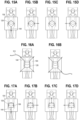
- FIGS. 15A-15D show several potential locations where the outlet tube 144 may enter the active area 128 of the vacuum pad 104.
- the location of the outlet tube 144 may enter the active drainage area where two or more edges of the active area 126 meet at a corner or vertex 170.
- including the outlet tube 144 at a vertex may create a funnel effect within the interior space of the active area 128 as blood moves towards the outlet tube 144.
- the vacuum pad 104 may be rotated such that the outlet tube 144 is in an accessible and convenient location for connection to the vacuum tube. That is, the vacuum pad 104 may work in several different orientations such that it can be placed under a patient body in a variety of ways.
- the vacuum pad 104 may include multiple outlet tubes 144, and/or other outlet structures, such that a particular outlet structure may be chosen and connected to the vacuum hose 110 (e.g., while others go unused).
- a particular outlet structure may be chosen and connected to the vacuum hose 110 (e.g., while others go unused).
- multiple vacuum hoses may be coupled to multiple outlets, and/or an outlet may be used as a tap for collection of a body fluid directly from the vacuum pad 104.
- FIG. 17 includes yet another embodiment where the outlet tubes 144 may be inserted into one or more ports 196.
- the outlet tube 144 may be connectable and disconnectable from the remainder of the vacuum pad 104 at different locations.
- the vacuum pad 104 may be placed on a surgery table in a desired location without needing to account for where the outlet tube 144 or hose will be located, which may reduce the need for perfect placement (particularly helpful in emergency situations).
- the outlet tube 144 can then be connected in a variety of locations, even after the patient is resting on the device.
- a first aspect includes a vacuum pad.
- the vacuum pad may include a top layer forming a top surface of the vacuum pad; a bottom layer forming a bottom surface of the vacuum pad; and a plurality of spacers located between the top layer and the bottom layer such that an interior space is formed between the top layer and the bottom layer, the interior space having at least one channel extending around at least one spacer of the plurality of spacers; and an outlet tube in fluid communication with the interior space.
- the top layer may include a plurality of holes such that the vacuum pad is configured to cause a fluid collecting on the top surface of the vacuum pad to flow through the holes, into the interior space, and to the outlet tube.
- a second aspect includes the vacuum pad from the aspect 1, where the vacuum pad of the first aspect may have the set of spacers of the plurality of spacers including air pockets.
- a third aspect includes the vacuum pad from any of aspects 1-2, where the bottom layer of the vacuum pad of the first aspect may include a spacer pad that at least partially forms the spacers.
- a fourth aspect includes the vacuum pad from any of aspects 1-3, where the plurality of openings forms a star arrangement having a central area with a plurality of branches extending radially outward therefrom.
- a fifth aspect includes the vacuum pad from any of aspects 1-4, where the outlet tube includes a rigid internal portion that extends along a drainage pattern, the drainage pattern including at least a portion of the holes in the top layer.
- a sixth aspect includes the vacuum pad from any of aspects 1-5, where the outlet tube enters an active area of the top layer at a vertex of the active area.
- a seventh aspect includes the vacuum pad from any of aspects 1-6 where an internal portion of the outlet tube includes a permeable structure for enhancing fluid flow into the internal portion, and where an external portion of the outlet tube includes a impermeable structure for preventing leaks at a location outside the interior space of the vacuum pad.
- An eighth aspect includes the vacuum pad from any of aspects 1-6, where a permeable support structure extends from the outlet tube for protecting fluid communication at a location adjacent to the outlet tube.
- a ninth aspect includes the vacuum pad from any of aspects 1-8, where an active area of the vacuum pad includes the spacers, and where the vacuum pad further comprises a boundary portion at least partially surrounding the active area, the boundary portion having a construction that is different than a construction of the active area.
- a tenth aspect includes vacuum pad from any of aspects 1-9, where the boundary portion includes a rigidity that is greater than a rigidity of the top layer of the active area.
- An eleventh aspect includes the vacuum pad from aspect 9, where the boundary portion includes at least one sloped surface for causing a fluid to flow towards the active area when fluid collects on the boundary portion.
- An twelfth aspect includes the vacuum pad from any of aspects 9-10, further including a barrier located between the boundary portion and the active area, the boundary portion protruding upwards relative to the top surface of the active area.
- a thirteenth aspect includes another embodiment of a vacuum pad.
- the vacuum pad may include an active area having a permeable top layer and a bottom layer such that an interior space is formed between the top layer and the bottom layer; a boundary portion surrounding the active area, the boundary portion having an impermeable top surface; and an outlet configured to couple to a vacuum source such that fluid collected on the active area is removed from the interior space towards the vacuum source.
- a fourteenth aspect includes the vacuum pad aspect 13, where the boundary portion includes a sloped surface for directing the fluid towards the active area.
- a fifteenth aspect includes the vacuum pad from any of aspects 13-14, where the boundary portion includes a first rectangle formed by its outer perimeter, where the active area includes a second rectangle formed by its outer perimeter, and where the first rectangle is angled relative to the second rectangle.
- a sixteenth aspect includes the vacuum pad from any of aspects 13-15, where the boundary portion is configured to at least partially form a top surface of a surgical table.
- a seventeenth aspect includes the vacuum pad from any of aspects 13-16, further including a fixture having a sloped surface for directing the fluid towards the active area.
- An eighteenth aspect includes a vacuum system.
- the vacuum system may include the following: a vacuum pad for collecting a fluid flowing onto a top surface of the vacuum pad, where the vacuum pad includes a permeable top layer, a bottom layer, and a plurality of spacers located between the top layer and the bottom layer; and a canister for storing a fluid collected by the vacuum pad, where the vacuum pad includes an outlet configured for securement to a first end of a vacuum hose, and where the canister includes an inlet configured for securement to a second end of the vacuum hose such that the vacuum hose directs the fluid collected by the vacuum pad to the canister.
- a nineteenth aspect includes the vacuum system of aspect 18, where the canister is coupled to a sensor for detecting a fluid level within the canister.
- a twentieth aspect includes the vacuum system of any of aspects 18-19, further including a vacuum source, where the vacuum source, the canister, the vacuum hose, and the vacuum pad are connected in series.
Landscapes
- Health & Medical Sciences (AREA)
- Life Sciences & Earth Sciences (AREA)
- Engineering & Computer Science (AREA)
- Veterinary Medicine (AREA)
- Public Health (AREA)
- General Health & Medical Sciences (AREA)
- Animal Behavior & Ethology (AREA)
- Biomedical Technology (AREA)
- Heart & Thoracic Surgery (AREA)
- Hematology (AREA)
- Pathology (AREA)
- Molecular Biology (AREA)
- Surgery (AREA)
- Biophysics (AREA)
- Physics & Mathematics (AREA)
- Medical Informatics (AREA)
- Gynecology & Obstetrics (AREA)
- Vascular Medicine (AREA)
- Anesthesiology (AREA)
- Dermatology (AREA)
- Pain & Pain Management (AREA)
- Manufacturing & Machinery (AREA)
- Pregnancy & Childbirth (AREA)
- Reproductive Health (AREA)
- External Artificial Organs (AREA)
- Containers, Films, And Cooling For Superconductive Devices (AREA)
- Manipulator (AREA)
- Surgical Instruments (AREA)
Priority Applications (1)
| Application Number | Priority Date | Filing Date | Title |
|---|---|---|---|
| EP24218596.5A EP4501230A3 (de) | 2021-10-12 | 2021-12-02 | Vakuumkissen und entsprechendes system |
Applications Claiming Priority (1)
| Application Number | Priority Date | Filing Date | Title |
|---|---|---|---|
| US17/499,346 US11413206B1 (en) | 2021-10-12 | 2021-10-12 | Vacuum pad and related system |
Related Child Applications (1)
| Application Number | Title | Priority Date | Filing Date |
|---|---|---|---|
| EP24218596.5A Division EP4501230A3 (de) | 2021-10-12 | 2021-12-02 | Vakuumkissen und entsprechendes system |
Publications (1)
| Publication Number | Publication Date |
|---|---|
| EP4166078A1 true EP4166078A1 (de) | 2023-04-19 |
Family
ID=78821205
Family Applications (2)
| Application Number | Title | Priority Date | Filing Date |
|---|---|---|---|
| EP24218596.5A Pending EP4501230A3 (de) | 2021-10-12 | 2021-12-02 | Vakuumkissen und entsprechendes system |
| EP21211975.4A Withdrawn EP4166078A1 (de) | 2021-10-12 | 2021-12-02 | Vakuumkissen und entsprechendes system |
Family Applications Before (1)
| Application Number | Title | Priority Date | Filing Date |
|---|---|---|---|
| EP24218596.5A Pending EP4501230A3 (de) | 2021-10-12 | 2021-12-02 | Vakuumkissen und entsprechendes system |
Country Status (6)
| Country | Link |
|---|---|
| US (2) | US11413206B1 (de) |
| EP (2) | EP4501230A3 (de) |
| JP (1) | JP2024537371A (de) |
| AU (1) | AU2022363358B8 (de) |
| CA (1) | CA3232107A1 (de) |
| WO (1) | WO2023063982A1 (de) |
Families Citing this family (5)
| Publication number | Priority date | Publication date | Assignee | Title |
|---|---|---|---|---|
| US20220079827A1 (en) * | 2020-09-15 | 2022-03-17 | Vimadri, LLC | Fluid collection device, related apparatus and method of using the same |
| US12478498B2 (en) * | 2022-07-19 | 2025-11-25 | James William Scott | Urine collection systems, and methods of making and using the same |
| US12343245B2 (en) * | 2022-07-19 | 2025-07-01 | James William Scott | Urine collection systems, and methods of making and using the same |
| CN117379271B (zh) * | 2023-12-06 | 2024-03-01 | 佳木斯大学 | 一次性分娩产妇血液收集计量袋 |
| WO2026019874A1 (en) * | 2024-07-17 | 2026-01-22 | Orlando Health, Inc. | Vacuum pad and related system |
Citations (5)
| Publication number | Priority date | Publication date | Assignee | Title |
|---|---|---|---|---|
| US3757356A (en) * | 1972-07-13 | 1973-09-11 | H Freeman | Therapeutic bed pan |
| EP0300621A1 (de) * | 1987-06-22 | 1989-01-25 | Takeda Chemical Industries, Ltd. | Saugeinrichtung für medizinische Operation |
| US5176667A (en) * | 1992-04-27 | 1993-01-05 | Debring Donald L | Liquid collection apparatus |
| US5827246A (en) * | 1996-02-28 | 1998-10-27 | Tecnol Medical Products, Inc. | Vacuum pad for collecting potentially hazardous fluids |
| US6102073A (en) * | 1998-07-13 | 2000-08-15 | Williams; Kevin M. | Fluid-collecting receptacle |
Family Cites Families (23)
| Publication number | Priority date | Publication date | Assignee | Title |
|---|---|---|---|---|
| US3889302A (en) * | 1974-05-13 | 1975-06-17 | Marta Carlota Ketterer | Fluid discharge unit |
| US4870710A (en) * | 1989-03-03 | 1989-10-03 | Richard Hartmann | Body-liquid collecting and mattress protecting apparatus |
| CA2070590C (en) * | 1991-12-16 | 2002-10-01 | Kimberly-Clark Worldwide, Inc. | Surgical fluid evacuation system |
| US5437651A (en) * | 1993-09-01 | 1995-08-01 | Research Medical, Inc. | Medical suction apparatus |
| US5870797A (en) | 1996-02-23 | 1999-02-16 | Anderson; Kent George | Vacuum cleaning system |
| US5655258A (en) * | 1996-03-12 | 1997-08-12 | Heintz; J. Aaron | Device for aspirating fluids from hospital operating room floor |
| US7086409B2 (en) * | 1998-02-09 | 2006-08-08 | Promethean Medical Technologies, Inc. | Fluid control island |
| US6685681B2 (en) * | 2000-11-29 | 2004-02-03 | Hill-Rom Services, Inc. | Vacuum therapy and cleansing dressing for wounds |
| US7043792B2 (en) | 2002-04-19 | 2006-05-16 | R&L Marketing & Sales, Inc. | Floor mat system with flanged cover |
| US7192409B2 (en) | 2002-08-26 | 2007-03-20 | Aida Iris Lorenzo | Comfort bandage |
| GB0308311D0 (en) | 2003-04-10 | 2003-05-14 | Bristol Myers Squibb Co | Wound dressing |
| US7128735B2 (en) * | 2004-01-02 | 2006-10-31 | Richard Scott Weston | Reduced pressure wound treatment appliance |
| US7905870B2 (en) | 2005-03-13 | 2011-03-15 | Harty Robert D | Device for collecting and measuring fluid loss |
| US7416576B2 (en) | 2006-01-27 | 2008-08-26 | Mecs, Inc. | Fiber bed assembly and fiber bed therefor |
| GB0620907D0 (en) | 2006-10-20 | 2006-11-29 | 3M Innovative Properties Co | Floor matting |
| TWI340653B (en) | 2007-11-09 | 2011-04-21 | Ind Tech Res Inst | Detachable pump and the negative pressure wound therapy system using the same |
| US9408755B2 (en) | 2007-11-13 | 2016-08-09 | Medela Holding Ag | Wound drainage dressing |
| CN101972511A (zh) | 2010-11-01 | 2011-02-16 | 葛劲超 | 一种手术切口表面的冲洗引流装置 |
| CA2833232C (en) | 2011-04-15 | 2018-05-22 | University Of Massachusetts | Surgical cavity drainage and closure system |
| WO2014014842A1 (en) | 2012-07-16 | 2014-01-23 | University Of Massachusetts | Negative pressure wound closure device |
| US10583228B2 (en) * | 2015-07-28 | 2020-03-10 | J&M Shuler Medical, Inc. | Sub-atmospheric wound therapy systems and methods |
| WO2017115146A1 (en) | 2015-12-30 | 2017-07-06 | Smith & Nephew Plc | Absorbent negative pressure wound therapy dressing |
| CN208905848U (zh) | 2018-05-31 | 2019-05-28 | 谢圆 | 防渗漏引流装置 |
-
2021
- 2021-10-12 US US17/499,346 patent/US11413206B1/en active Active
- 2021-12-02 EP EP24218596.5A patent/EP4501230A3/de active Pending
- 2021-12-02 EP EP21211975.4A patent/EP4166078A1/de not_active Withdrawn
-
2022
- 2022-02-18 CA CA3232107A patent/CA3232107A1/en active Pending
- 2022-02-18 AU AU2022363358A patent/AU2022363358B8/en active Active
- 2022-02-18 WO PCT/US2022/016949 patent/WO2023063982A1/en not_active Ceased
- 2022-02-18 JP JP2024522352A patent/JP2024537371A/ja active Pending
- 2022-08-15 US US17/819,846 patent/US12042438B2/en active Active
Patent Citations (5)
| Publication number | Priority date | Publication date | Assignee | Title |
|---|---|---|---|---|
| US3757356A (en) * | 1972-07-13 | 1973-09-11 | H Freeman | Therapeutic bed pan |
| EP0300621A1 (de) * | 1987-06-22 | 1989-01-25 | Takeda Chemical Industries, Ltd. | Saugeinrichtung für medizinische Operation |
| US5176667A (en) * | 1992-04-27 | 1993-01-05 | Debring Donald L | Liquid collection apparatus |
| US5827246A (en) * | 1996-02-28 | 1998-10-27 | Tecnol Medical Products, Inc. | Vacuum pad for collecting potentially hazardous fluids |
| US6102073A (en) * | 1998-07-13 | 2000-08-15 | Williams; Kevin M. | Fluid-collecting receptacle |
Also Published As
| Publication number | Publication date |
|---|---|
| JP2024537371A (ja) | 2024-10-10 |
| WO2023063982A1 (en) | 2023-04-20 |
| EP4501230A3 (de) | 2025-07-09 |
| CA3232107A1 (en) | 2023-04-20 |
| AU2022363358A1 (en) | 2024-05-02 |
| EP4501230A2 (de) | 2025-02-05 |
| AU2022363358B8 (en) | 2025-08-07 |
| US12042438B2 (en) | 2024-07-23 |
| AU2022363358B1 (en) | 2025-07-17 |
| US20230114026A1 (en) | 2023-04-13 |
| US11413206B1 (en) | 2022-08-16 |
Similar Documents
| Publication | Publication Date | Title |
|---|---|---|
| US11413206B1 (en) | Vacuum pad and related system | |
| KR102513810B1 (ko) | 유체 수집 장치, 시스템 및 방법 | |
| KR102849134B1 (ko) | 유체 수집 장치, 시스템 및 방법 | |
| EP4274524B1 (de) | Flüssigkeitsaufnahmegerät, konfiguriert als ein männliches urinaufnahmegerät | |
| AU651918B2 (en) | Surgical fluid evacuation system | |
| TW201805036A (zh) | 流體收集裝置 | |
| US20220039995A1 (en) | Fluid collection devices including an enlarged base, and systems and methods of use | |
| ES2315018T3 (es) | Terapia de presion negativa usando succion de pared. | |
| JP7356358B2 (ja) | 長時間装着用多層創傷充填材 | |
| CA2247104C (en) | Device for aspirating fluids from hospital operating room floor | |
| US6235009B1 (en) | Surgical wicking and fluid removal platform | |
| US20050197639A1 (en) | Liquid removal method and apparatus for surgical procedures | |
| US20160144085A1 (en) | Fluid transport dressing | |
| PT865304E (pt) | Aparelho portatil para tratamento de ferimentos | |
| EP2268348A1 (de) | Vorrichtung zur wundbehandlung mit reduziertem druck | |
| JP2013521954A (ja) | 医療用真空シール排液装置 | |
| US10850014B2 (en) | Liquid collection device and method | |
| HK40092170A (en) | Vacuum pad and related system | |
| HK40118246A (en) | Vacuum pad and related system | |
| US20240366454A1 (en) | Vacuum pad and related system | |
| WO2026019874A1 (en) | Vacuum pad and related system | |
| US20230190562A1 (en) | Surgical fluid retention device and method of use |
Legal Events
| Date | Code | Title | Description |
|---|---|---|---|
| PUAI | Public reference made under article 153(3) epc to a published international application that has entered the european phase |
Free format text: ORIGINAL CODE: 0009012 |
|
| STAA | Information on the status of an ep patent application or granted ep patent |
Free format text: STATUS: THE APPLICATION HAS BEEN PUBLISHED |
|
| AK | Designated contracting states |
Kind code of ref document: A1 Designated state(s): AL AT BE BG CH CY CZ DE DK EE ES FI FR GB GR HR HU IE IS IT LI LT LU LV MC MK MT NL NO PL PT RO RS SE SI SK SM TR |
|
| STAA | Information on the status of an ep patent application or granted ep patent |
Free format text: STATUS: REQUEST FOR EXAMINATION WAS MADE |
|
| 17P | Request for examination filed |
Effective date: 20231016 |
|
| RBV | Designated contracting states (corrected) |
Designated state(s): AL AT BE BG CH CY CZ DE DK EE ES FI FR GB GR HR HU IE IS IT LI LT LU LV MC MK MT NL NO PL PT RO RS SE SI SK SM TR |
|
| RIN1 | Information on inventor provided before grant (corrected) |
Inventor name: WHITEHOUSE, NEIL Inventor name: DESAI, NEERAJ Inventor name: LANCE, TERESA |
|
| REG | Reference to a national code |
Ref country code: HK Ref legal event code: DE Ref document number: 40092170 Country of ref document: HK |
|
| GRAP | Despatch of communication of intention to grant a patent |
Free format text: ORIGINAL CODE: EPIDOSNIGR1 |
|
| STAA | Information on the status of an ep patent application or granted ep patent |
Free format text: STATUS: GRANT OF PATENT IS INTENDED |
|
| INTG | Intention to grant announced |
Effective date: 20240812 |
|
| STAA | Information on the status of an ep patent application or granted ep patent |
Free format text: STATUS: THE APPLICATION IS DEEMED TO BE WITHDRAWN |
|
| 18D | Application deemed to be withdrawn |
Effective date: 20241213 |