EP4166253B1 - Abkantpresse - Google Patents
Abkantpresse Download PDFInfo
- Publication number
- EP4166253B1 EP4166253B1 EP21825449.8A EP21825449A EP4166253B1 EP 4166253 B1 EP4166253 B1 EP 4166253B1 EP 21825449 A EP21825449 A EP 21825449A EP 4166253 B1 EP4166253 B1 EP 4166253B1
- Authority
- EP
- European Patent Office
- Prior art keywords
- elevating
- stretch
- elevating member
- lateral direction
- pair
- Prior art date
- Legal status (The legal status is an assumption and is not a legal conclusion. Google has not performed a legal analysis and makes no representation as to the accuracy of the status listed.)
- Active
Links
Images




Classifications
-
- B—PERFORMING OPERATIONS; TRANSPORTING
- B21—MECHANICAL METAL-WORKING WITHOUT ESSENTIALLY REMOVING MATERIAL; PUNCHING METAL
- B21D—WORKING OR PROCESSING OF SHEET METAL OR METAL TUBES, RODS OR PROFILES WITHOUT ESSENTIALLY REMOVING MATERIAL; PUNCHING METAL
- B21D5/00—Bending sheet metal along straight lines, e.g. to form simple curves
- B21D5/002—Positioning devices
-
- B—PERFORMING OPERATIONS; TRANSPORTING
- B21—MECHANICAL METAL-WORKING WITHOUT ESSENTIALLY REMOVING MATERIAL; PUNCHING METAL
- B21D—WORKING OR PROCESSING OF SHEET METAL OR METAL TUBES, RODS OR PROFILES WITHOUT ESSENTIALLY REMOVING MATERIAL; PUNCHING METAL
- B21D43/00—Feeding, positioning or storing devices combined with, or arranged in, or specially adapted for use in connection with, apparatus for working or processing sheet metal, metal tubes or metal profiles; Associations therewith of cutting devices
- B21D43/26—Stops
-
- B—PERFORMING OPERATIONS; TRANSPORTING
- B21—MECHANICAL METAL-WORKING WITHOUT ESSENTIALLY REMOVING MATERIAL; PUNCHING METAL
- B21D—WORKING OR PROCESSING OF SHEET METAL OR METAL TUBES, RODS OR PROFILES WITHOUT ESSENTIALLY REMOVING MATERIAL; PUNCHING METAL
- B21D5/00—Bending sheet metal along straight lines, e.g. to form simple curves
- B21D5/02—Bending sheet metal along straight lines, e.g. to form simple curves on press brakes without making use of clamping means
-
- B—PERFORMING OPERATIONS; TRANSPORTING
- B21—MECHANICAL METAL-WORKING WITHOUT ESSENTIALLY REMOVING MATERIAL; PUNCHING METAL
- B21D—WORKING OR PROCESSING OF SHEET METAL OR METAL TUBES, RODS OR PROFILES WITHOUT ESSENTIALLY REMOVING MATERIAL; PUNCHING METAL
- B21D5/00—Bending sheet metal along straight lines, e.g. to form simple curves
- B21D5/02—Bending sheet metal along straight lines, e.g. to form simple curves on press brakes without making use of clamping means
- B21D5/0281—Workpiece supporting devices
-
- B—PERFORMING OPERATIONS; TRANSPORTING
- B30—PRESSES
- B30B—PRESSES IN GENERAL
- B30B15/00—Details of, or accessories for, presses; Auxiliary measures in connection with pressing
- B30B15/08—Accessory tools, e.g. knives; Mountings therefor
-
- B—PERFORMING OPERATIONS; TRANSPORTING
- B30—PRESSES
- B30B—PRESSES IN GENERAL
- B30B15/00—Details of, or accessories for, presses; Auxiliary measures in connection with pressing
- B30B15/30—Feeding material to presses
Definitions
- the present invention relates to a press brake that bends a plate-shaped workpiece (a sheet metal) by the collaboration between an upper tool and a lower tool.
- a press brake is provided with a back gauge device for positioning a workpiece in the front-rear direction with respect to a lower tool (see Patent Literatures 1 to 3).
- the outline of the configuration of the back gauge device will be described below.
- a pair of support blocks separated in the lateral direction are provided on the back side of a lower table in a main frame, and the pair of support blocks are first and second support blocks. Elevating members extending vertically are provided to the respective support blocks so as to be able to ascend and descend, and the pair of elevating members are first and second elevating members. Further, a stretch extending in the lateral direction is provided between the upper end portion of the first elevating member and the upper end portion of the second elevating member. One end side of the stretch in the lateral direction is fixed to the upper end portion of the first elevating member, and the other end side of the stretch in the lateral direction is fixed to the upper end portion of the second elevating member.
- each of the abutting members includes an abutting surface, on the distal end side thereof, against which the end surface of the plate-shaped workpiece can be abutted.
- Each of the abutting members is configured to be movable in the lateral direction and the front-rear direction with respect to the main frame.
- the abutting surface of each of the abutting members is positioned at a height position corresponding to the height of the lower tool by an elevating operation of the pair of elevating members.
- the back gauge device is divided into a first type that performs the elevating operation of the pair of elevating members by driving two motors (see Patent Literature 1 and Patent Literature 2), and a second type that performs the elevating operation of the pair of elevating members by driving one motor (see Patent Literature 3). Since the number of motors is reduced in the second type back gauge device, the cost of the press brake can be lowered as compared with the first type back gauge device.
- the configuration for ascending and descending the pair of elevating members will be described below.
- Ball screws (screw bolts in Patent Literature 3) extending vertically are provided to respective ends of the stretch in the lateral direction so as to be hanged down.
- a nut member is provided on the upper end side of each of the elevating members (upper and lower guide pins in Patent Literature 3) via a separate member (a front-rear moving beam member in Patent Literature 3), and each of the nut members is screwed into each of the ball screws.
- a motor (a servo motor for vertical movement in Patent Literature 3), which causes a pair of nuts to be rotated, is provided on the upper end side of the first elevating member. An output shaft of the motor is interlocked and connected to the pair of nut members via a chain or a timing belt.
- the second type back gauge device includes the pair of ball screws and the pair of nut members.
- the second type back gauge device includes two ball screw mechanisms for elevation, each of which includes the ball screw and the nut member. Therefore, in the second type back gauge device, adjustment for synchronizing the two ball screw mechanisms for elevation is required, which causes a problem that the adjustment work of the back gauge device requires a lot of time and effort.
- a press brake according to the present invention is defined in independent claim 1.
- the dependent claim defines a preferred embodiment.
- the pair of support blocks, the pair of elevating members, the stretch, the support mechanism, and the abutting member constitute a part of a back gauge device for positioning a workpiece in the front-rear direction with respect to a lower tool installed on the lower table.
- the one end side of the stretch in the lateral direction is connected to the upper end portion of the first elevating member.
- the other end side of the stretch in the lateral direction is connected to the upper end portion of the second elevating member.
- the support mechanism that supports the stretch from below is provided to the first elevating member. Therefore, by providing only one ball screw mechanism for elevation, which includes the ball screw and the nut member, to the back gauge device, the pair of elevating members can be ascended and descended by the driving of one motor. Therefore, it is possible to simplify the adjustment work of the back gauge device while reducing the cost of the press brake.
- the term “provided” means not only directly provided but also indirectly provided via another member.
- the term “lateral direction” is one of the horizontal directions, which is a lateral direction of the press brake, and is also referred to as the Y-axis direction.
- the phrase “inside in the lateral direction” means the center side of the press brake in the lateral direction.
- the term “front-rear direction” is a horizontal direction orthogonal to the lateral direction, which is a depth direction of the press brake, and is also referred to as the L-axis direction.
- FF indicates the front direction
- FR indicates the rear direction
- L indicates the left direction
- R indicates the right direction
- U indicates the upward direction
- “D” indicates the downward direction.
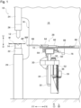
- a press brake 10 is a working machine that bends a plate-shaped workpiece (a sheet metal) W by the collaboration between an upper tool (punch tool) 12 and a lower tool (die tool) 14.
- the press brake 10 includes with a main frame 16, and the main frame 16 includes a pair of side plates 18 that are separated and opposed to each other in the lateral direction, and a plurality of connecting members (not shown) that integrally connect the pair of side plates 18.
- the pair of side plates 18 are first (left side) and second (right side) side plates 18.
- a lower table 20 extending in the lateral direction is provided at the lower part of the front surface side (the front side) of the main frame 16.
- a lower tool holder 22, which retains the lower tool 14 so as to be installable and removeable, is provided on the upper side of the lower table 20.
- an upper table 24 extending in the lateral direction is provided at the upper part of the front surface side of the main frame 16 so as to be able to ascend and descend (so as to be vertically movable).
- the upper table 24 is ascended and descended by the driving of an elevating hydraulic cylinder (not shown) or an elevating motor (not shown) as an elevating actuator for a table provided at an appropriate position on the main frame 16.
- the lower table 20 may be configured so as to be able to ascend and descend.
- a back gauge device 28 for positioning the workpiece W in the front-rear direction with respect to the lower tool 14 is provided on the back side (the rear side) of the lower table 20 in the main frame 16.
- the back gauge device 28 provided inside in the lateral direction of the second (right side) side plate 18 is illustrated on the back side (the rear side) of the lower table 20.
- the specific configuration of the back gauge device 28 will be described below.
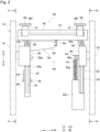
- a pair of support blocks (guide blocks) 30, which are separated and opposed to each other in the lateral direction, are provided on the back side of the lower table 20 in the main frame 16.
- the pair of support blocks 30 are first (left side) and second (right side) support blocks 30.
- the first support block 30 is fixed to the first side plate 18, and the second support block 30 is fixed to the second side plate 18.
- Each of the support blocks 30 has, on the back side thereof, a guide portion 30g extending vertically.
- Each of the support blocks 30 includes, inside in the lateral direction thereof, a protrusion 30p that protrudes in the rear direction.
- an elevating member 32 extending vertically is provided via a slide rail 34 to the guide portion 30g of each of the support blocks 30 so as to be able to ascend and descend.
- the pair of elevating members 32 are first (left side) and second (right side) elevating members 32.
- the first elevating member 32 includes, on the back side thereof, two protrusions 32p and 32b that are vertically separated.
- the second elevating member 32 includes, on the lower end side thereof, an extending portion 32e extending downward. Note that the drawings of the present application show, as an example, a state in which the pair of elevating members 32 are positioned at the lowest position.
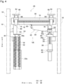
- a ball screw 36 extending vertically is provided between the two protrusions 32p and 32b of the first elevating member 32 so as to be rotatable.
- An elevating motor 38 that causes the ball screw 36 to rotate is provided, via a bracket 40, to the protrusion 32b of the first elevating member 32.
- An output shaft of the elevating motor 38 is interlocked and connected to the ball screw 36 via two pulleys 42 and 44 and a timing belt 46.
- the ball screw 36 is ascended and descended while being rotated by the driving of the elevating motor 38.
- a nut member 48 screwed into the ball screw 36 is provided to the protrusion 30p of the first support block 30.
- the back gauge device 28 includes one ball screw mechanism for elevation, which includes the ball screw 36 and the nut member 48.
- the ball screw 36 may be provided to the first support block 30 so as to be rotatable.
- the nut member 48 is provided not to the first support block 30 but to the first elevating member 32.
- An electromagnetic brake 50 that secures the ball screw 36 in a nonrotatable manner is provided to the protrusion 32p of the first elevating member 32.
- the electromagnetic brake 50 is configured to secure the ball screw 36 by a braking force in a nonrotatable manner when the power of the press brake 10 is turned off.
- the electromagnetic brake 50 is a body separated from the elevating motor 38, but the elevating motor 38 may include the electromagnetic brake.
- the back gauge device 28 may include another brake (not shown) that secures the ball screw 36 in a nonrotatable manner in lieu of the electromagnetic brake 50.
- a plurality of tension springs 52 are provided in parallel between the protrusion 30p of the second support block 30 and the extending portion 32e of the second elevating member 32, as balancers that reduce gravity acting on the second elevating member 32.
- the plurality of tension springs 52 are urging members that urge the second elevating member 32 upward.
- the upper end portion of each of the tension springs 52 is locked to the protrusion 30p of the second support block 30 via a bracket 54, and the lower end portion of each of the tension springs 52 is locked to the lower end portion of the extending portion 32e of the second elevating member 32.
- a square pipe-shaped stretch 56 extending in the lateral direction is provided between the upper end portion of the first elevating member 32 and the upper end portion of the second elevating member 32.
- the stretch 56 includes connecting portions 56j and 56c on one end side and the other end side in the lateral direction thereof, respectively.
- the connecting portion 56j of the stretch 56 is connected, so as to be rotationally movable (swingable), to the upper end portion of the first elevating member 32 via a first connecting bolt 58 as a first connecting pin.
- the first connecting bolt 58 is screwed into the upper end portion of the first elevating member 32.
- the connecting portion 56c of the stretch 56 is connected, so as to be rotationally movable, to the upper end portion of the second elevating member 32 via a second connecting bolt 60 as a second connecting pin.
- the second connecting bolt 60 is screwed into the upper end portion of the second elevating member 32.
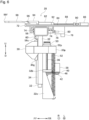
- a support mechanism 62 that supports the stretch 56 from below is provided on the upper end side of the first elevating member 32.
- the support mechanism 62 includes a support base 64 provided on the upper end side of the first elevating member 32 and extending inside in the lateral direction.
- the support mechanism 62 includes an adjusting screw 66 that is provided by being screwed into a distal end portion of the support base 64 and that contacts (supports) the stretch 56 from below, and upper and lower lock nuts 68 and 70 that prevent the adjusting screw 66 from being loosened.
- the support mechanism 62 adjusts levelness of the stretch 56 when the stretch 56 moves rotationally around the first connecting bolt 58.
- a pair of Y-axis sliders 72 is provided to the stretch 56 so as to be movable in the lateral direction via a plurality of guide rails 74.
- Each of the Y-axis sliders 72 extends in the front-rear direction.
- a Y-axis motor 76 which causes each of the Y-axis sliders 72 to move in the lateral direction with respect to the stretch 56, is provided on the back side of each of the Y-axis sliders 72.
- a rack member 78 extending in the lateral direction is provided on the back surface of the stretch 56.
- a pinion 80 is provided to an output shaft of each of the Y-axis motors 76, and each of the pinions 80 is engaged with the rack member 78. Note that as an example, the drawings of the present application show a state in which the pair of Y-axis sliders 72 are most separated in the lateral direction.
- An L-axis slider 82 is provided on the upper surface of each of the Y-axis sliders 72 so as to be movable in the front-rear direction via a pair of guide rails 84.
- An L-axis motor 86 which causes each of the L-axis sliders 82 to move in the front-rear direction with respect to each of the Y-axis sliders 72, is provided at the rear end portion of each of the Y-axis sliders 72.
- an abutting base 94 is provided on the upper surface of each of the L-axis sliders 82, and a mounting shaft 96 is provided to a distal end portion of each of the abutting bases 94.
- An abutting member 98 which has a known configuration that is shown in Patent Literature 2, is provided to each of the mounting shafts 96.
- the pair of abutting members 98 are provided to the stretch 56 via the pair of Y-axis sliders 72, the pair of L-axis sliders 82, and the like.
- Each of the abutting members 98 includes, on a distal end side thereof, an abutting surface 98f against which an end surface Wf of the workpiece W can be abutted.
- Each of the abutting members 98 is configured to be movable in the lateral direction and the front-rear direction with respect to the main frame 16.
- Each of the abutting members 98 moves in the lateral direction integrally with the Y-axis slider 72 with respect to the main frame 16 by the driving of the Y-axis motor 76.
- Each of the abutting members 98 moves in the front-rear direction integrally with the L-axis slider 82 with respect to the main frame 16 by the driving of the L-axis motor 86.
- Each of the abutting members 98 is configured to be able to be installed to and removed from each of the mounting shafts 96 and to be able to be folded up with an axial center of each of the mounting shafts 96 as a center.
- the pair of elevating members 32 are ascended and descended by the driving of the elevating motor 38.
- the stretch 56 is ascended and descended integrally with the pair of elevating members 32, which causes the abutting surface 98f of each of the abutting members 98 to be positioned at a height position corresponding to the lower tool 14.
- each of the abutting members 98 is moved in the lateral direction integrally with each of the Y-axis sliders 72 by the driving of each of the Y-axis motors 76.
- the interval in the lateral direction between the pair of abutting members 98 is adjusted according to a bending length of the workpiece W.
- each of the abutting members 98 is moved in the front-rear direction integrally with each of the L-axis sliders 82 by the driving of each of the L-axis motors 86, which causes the abutting surface 98f of each of the abutting members 98 to be positioned at a predetermined position in the front-rear direction.
- the workpiece W is moved in the rear direction and the end surface Wf of the workpiece W is abutted against the abutting surfaces 98f of the pair of abutting members 98. Thereby the workpiece W is positioned in the front-rear direction with respect to the lower tool 14. Then, the upper table 24 is lowered, which causes the workpiece W to be bent by the collaboration between the upper tool 12 and the lower tool 14. At this time, since each of the abutting members 98 is folded up with the axial center of each of the mounting shafts 96 as a center, it is possible to prevent damage to the abutting member 98 and the like, which is caused by the folding-up of the workpiece W. Note that after the workpiece W is bent, the upper table 24 is raised to return to the original state.
- the connecting portion 56j of the stretch 56 is connected, so as to be rotationally movable, to the upper end portion of the first elevating member 32 via the first connecting bolt 58.
- the connecting portion 56c of the stretch 56 is connected, so as to rotationally movable, to the upper end portion of the second elevating member 32 via the second connecting bolt 60.
- the second connecting bolt 60 is screwed into the upper end portion of the second elevating member 32.
- the support mechanism 62 that supports the stretch 56 from below is provided on the upper end side of the first elevating member 32.
- the plurality of tension springs 52 that reduce the gravity acting on the second elevating member 32 are provided in parallel between the protrusion 30p of the second support block 30 and the extending portion 32e of the second elevating member 32. Therefore, by providing only one ball screw mechanism for elevation, which includes the ball screw 36 and the nut member 48, to the back gauge device 28, the pair of elevating members 32 can be ascended and descended by the driving of one elevating motor 38.
- the power of the press brake 10 is turned off and the ball screw 36 is secured in a nonrotatable manner by the electromagnetic brake 50. Then, the stretch 56 is moved rotationally around the first connecting bolt 58 so that the stretch 56 becomes level by a rotary operation of the adjusting screw 66 in a state in which the gravity acting on the second elevating member 32 is reduced by the plurality of tension springs 52. As a result, the levelness of the stretch 56 can be easily adjusted.
Landscapes
- Engineering & Computer Science (AREA)
- Mechanical Engineering (AREA)
- Bending Of Plates, Rods, And Pipes (AREA)
Claims (2)
- Abkantpresse (10), umfassend:ein Paar Stützblöcke (30), die auf einer Rückseite eines unteren Tisches (20) in einem Hauptrahmen (16) vorgesehen sind und in einer seitlichen Richtung getrennt sind;Hubelemente (32), die jeweils an einem entsprechenden des Paars von Stützblöcken (30) vorgesehen sind, so dass sie auf- und absteigen können und sich vertikal erstrecken;ein Kugelgewindetrieb (36), der so vorgesehen ist, dass er zu einem ersten Hubelement eines Paars der Hubelemente (32) oder einem ersten Stützblock des Paars von Stützblöcken (30) drehbar ist, sich vertikal erstreckt und so konfiguriert ist, dass er durch einen Antrieb eines Motors (38) gedreht wird;ein Mutternelement (48), das an dem ersten Stützblock (30) oder dem ersten Hubelement (32) vorgesehen ist und in die Kugelumlaufspindel (36) geschraubt ist;eine Strecke (56), die sich in der seitlichen Richtung erstreckt, wobei eine Endseite der Strecke (56) in der seitlichen Richtung mit einem oberen Endabschnitt des ersten Hubelements (32) verbunden ist und eine andere Endseite der Strecke (56) in der seitlichen Richtung mit einem oberen Endabschnitt eines zweiten Hubelements (32) des Paars von Hubelementen (32) verbunden ist;ein an der Strecke (56) vorgesehenes Anschlagelement (98), wobei das Anschlagelement (98) an einer distalen Endseite eine Anschlagfläche (98f) umfasst, gegen die eine Endfläche (Wf) eines plattenförmigen Werkstücks (W) anliegen kann, wobei das Anschlagelement (98) so konfiguriert ist, dass es in Bezug auf den Hauptrahmen (16) in einer Richtung von vorne nach hinten beweglich ist; undeinen Stützmechanismus (62), der an dem ersten Hubelement (32) vorgesehen ist, um die Strecke (56) von unten zu stützen,dadurch gekennzeichnet, dassdie Abkantpresse (10) ferner eine Bremse (50) umfasst, die so konfiguriert ist, dass sie den Kugelgewindetrieb (36) in einer nicht drehbaren Weise sichert, wobei eine Endseite der Strecke (56) in der seitlichen Richtung mit dem oberen Endabschnitt des ersten Hubelements (32) über einen ersten Verbindungsstift (58) verbunden ist, so dass sie drehbeweglich ist, und eine andere Endseite der Strecke (56) in der seitlichen Richtung mit dem oberen Endabschnitt des zweiten Hubelements (32) über einen zweiten Verbindungsstift (60) verbunden ist, so dass sie drehbeweglich ist, undder Stützmechanismus (62) umfasst:eine Stützbasis (64), die an dem ersten Hubelement (32) vorgesehen ist, undeine Einstellschraube (66), die durch Einschrauben in die Stützbasis (64) so vorgesehen ist, dass sie die Strecke (56) von unten berührt.
- Die Abkantpresse (10) nach Anspruch 1, ferner umfassend Eine Ausgleichsvorrichtung (52), die ein zwischen dem zweiten Stützblock (30) und dem zweiten Hubelement (32) vorgesehenes Druckelement ist und so konfiguriert ist, dass sie das zweite Hubelement (32) nach oben drückt, um die auf das zweite Hubelement (32) wirkende Schwerkraft zu verringern.
Applications Claiming Priority (2)
| Application Number | Priority Date | Filing Date | Title |
|---|---|---|---|
| JP2020102874A JP7474643B2 (ja) | 2020-06-15 | 2020-06-15 | プレスブレーキ |
| PCT/JP2021/021479 WO2021256305A1 (ja) | 2020-06-15 | 2021-06-07 | プレスブレーキ |
Publications (3)
| Publication Number | Publication Date |
|---|---|
| EP4166253A1 EP4166253A1 (de) | 2023-04-19 |
| EP4166253A4 EP4166253A4 (de) | 2023-11-29 |
| EP4166253B1 true EP4166253B1 (de) | 2025-01-22 |
Family
ID=79196832
Family Applications (1)
| Application Number | Title | Priority Date | Filing Date |
|---|---|---|---|
| EP21825449.8A Active EP4166253B1 (de) | 2020-06-15 | 2021-06-07 | Abkantpresse |
Country Status (5)
| Country | Link |
|---|---|
| US (1) | US12240027B2 (de) |
| EP (1) | EP4166253B1 (de) |
| JP (1) | JP7474643B2 (de) |
| CN (1) | CN115702049B (de) |
| WO (1) | WO2021256305A1 (de) |
Family Cites Families (14)
| Publication number | Priority date | Publication date | Assignee | Title |
|---|---|---|---|---|
| JP3131269B2 (ja) | 1991-03-22 | 2001-01-31 | 株式会社アマダ | 板材加工装置 |
| DE69203307T2 (de) * | 1991-03-22 | 1995-11-02 | Amada Co | System zum bearbeiten von plattenmaterial. |
| JP2602953Y2 (ja) * | 1993-10-18 | 2000-02-07 | 株式会社小松製作所 | 折曲げ機のワーク架台 |
| JPH09253754A (ja) * | 1996-03-27 | 1997-09-30 | Amada Co Ltd | バックゲージサポータの撓み防止装置 |
| WO1998005442A1 (fr) * | 1996-08-05 | 1998-02-12 | Amada Co., Ltd. | Dispositif de butee arriere |
| JP3049011U (ja) * | 1997-11-18 | 1998-05-29 | 折尾精密株式会社 | 樹脂封止用金型装置 |
| JP2001062515A (ja) | 1999-08-30 | 2001-03-13 | Amada Co Ltd | バックゲージ装置 |
| JP2010162558A (ja) | 2009-01-13 | 2010-07-29 | Amada Co Ltd | 曲げ加工機 |
| KR20120025868A (ko) * | 2010-09-08 | 2012-03-16 | 선보선 | 판금가공기계의 백 게이지 장치 |
| AT514077B1 (de) * | 2013-06-20 | 2014-10-15 | Trumpf Maschinen Austria Gmbh | Hinteranschlagvorrichtung für eine Biegemaschine |
| CN205834030U (zh) * | 2016-08-05 | 2016-12-28 | 天津市泓金泰特种机械有限公司 | 一种弯管机横梁 |
| JP6606566B2 (ja) | 2018-01-29 | 2019-11-13 | 株式会社アマダホールディングス | プレスブレーキ |
| CN110405007B (zh) * | 2019-08-23 | 2024-05-24 | 江苏弘东工业自动化有限公司 | 基于伺服驱动的柔性折弯机 |
| JP6875027B2 (ja) | 2020-03-16 | 2021-05-19 | 株式会社コルグ | コンプレッサ |
-
2020
- 2020-06-15 JP JP2020102874A patent/JP7474643B2/ja active Active
-
2021
- 2021-06-07 US US18/007,932 patent/US12240027B2/en active Active
- 2021-06-07 CN CN202180042970.6A patent/CN115702049B/zh active Active
- 2021-06-07 WO PCT/JP2021/021479 patent/WO2021256305A1/ja not_active Ceased
- 2021-06-07 EP EP21825449.8A patent/EP4166253B1/de active Active
Also Published As
| Publication number | Publication date |
|---|---|
| WO2021256305A1 (ja) | 2021-12-23 |
| JP2021194681A (ja) | 2021-12-27 |
| EP4166253A1 (de) | 2023-04-19 |
| US20230241659A1 (en) | 2023-08-03 |
| CN115702049B (zh) | 2025-10-03 |
| EP4166253A4 (de) | 2023-11-29 |
| CN115702049A (zh) | 2023-02-14 |
| JP7474643B2 (ja) | 2024-04-25 |
| US12240027B2 (en) | 2025-03-04 |
Similar Documents
| Publication | Publication Date | Title |
|---|---|---|
| US8220134B2 (en) | Flexible fastening machine tool | |
| US20140283576A1 (en) | Sheet material processing apparatus, press die, and die setting body | |
| US20070051157A1 (en) | Work transfer device for press machines | |
| EP0530375A1 (de) | System zum bearbeiten von plattenmaterial | |
| US6220137B1 (en) | Press apparatus | |
| US6648568B2 (en) | Linear blind broaching machine | |
| CN105964763B (zh) | 一种冲孔生产主机 | |
| CN116867621B (zh) | 用于加工板状工件的机床的再调整装置及用于再调整板状工件以在机床中进行加工的方法 | |
| EP4166253B1 (de) | Abkantpresse | |
| KR101079283B1 (ko) | 변형을 최소화 하는 중,대형 가공기 | |
| JP2009006344A (ja) | ヘミング加工装置,ヘミング加工方法およびヘミング加工装置におけるスライド部の隙間調整方法 | |
| EP1068910B1 (de) | Modulares bördelsystem und bördelkopf | |
| CN114799964B (zh) | 一种设备零部件生产用加工设备 | |
| CN213033461U (zh) | 折弯件及直形件的送进设备 | |
| JPH0584520A (ja) | 板材加工装置 | |
| CN223629327U (zh) | 一种普车冲孔装置 | |
| EP4164819B1 (de) | Plattenbiegevorrichtung zum biegen von blech | |
| CN221269492U (zh) | 一种金属篮冲压成型装置 | |
| CN119304016B (zh) | 一种折弯装置 | |
| CN222551812U (zh) | 重型立式卷边机 | |
| JP2016215230A (ja) | 曲げ加工装置 | |
| CN120901209B (zh) | 用于固定链锯导板导轮的自动旋铆机 | |
| CN114378241B (zh) | 一种机械刃模具用工件锻压加工支撑装置及方法 | |
| CN215902497U (zh) | 一种中厚板轧机压下装置 | |
| CN216937789U (zh) | 一种车用铜排加工用矫直机 |
Legal Events
| Date | Code | Title | Description |
|---|---|---|---|
| STAA | Information on the status of an ep patent application or granted ep patent |
Free format text: STATUS: THE INTERNATIONAL PUBLICATION HAS BEEN MADE |
|
| PUAI | Public reference made under article 153(3) epc to a published international application that has entered the european phase |
Free format text: ORIGINAL CODE: 0009012 |
|
| STAA | Information on the status of an ep patent application or granted ep patent |
Free format text: STATUS: REQUEST FOR EXAMINATION WAS MADE |
|
| 17P | Request for examination filed |
Effective date: 20221116 |
|
| AK | Designated contracting states |
Kind code of ref document: A1 Designated state(s): AL AT BE BG CH CY CZ DE DK EE ES FI FR GB GR HR HU IE IS IT LI LT LU LV MC MK MT NL NO PL PT RO RS SE SI SK SM TR |
|
| DAV | Request for validation of the european patent (deleted) | ||
| DAX | Request for extension of the european patent (deleted) | ||
| A4 | Supplementary search report drawn up and despatched |
Effective date: 20231102 |
|
| RIC1 | Information provided on ipc code assigned before grant |
Ipc: B21D 43/26 20060101ALI20231026BHEP Ipc: B21D 43/00 20060101ALI20231026BHEP Ipc: B21D 5/02 20060101AFI20231026BHEP |
|
| STAA | Information on the status of an ep patent application or granted ep patent |
Free format text: STATUS: EXAMINATION IS IN PROGRESS |
|
| 17Q | First examination report despatched |
Effective date: 20240516 |
|
| GRAP | Despatch of communication of intention to grant a patent |
Free format text: ORIGINAL CODE: EPIDOSNIGR1 |
|
| STAA | Information on the status of an ep patent application or granted ep patent |
Free format text: STATUS: GRANT OF PATENT IS INTENDED |
|
| INTG | Intention to grant announced |
Effective date: 20241025 |
|
| GRAS | Grant fee paid |
Free format text: ORIGINAL CODE: EPIDOSNIGR3 |
|
| P01 | Opt-out of the competence of the unified patent court (upc) registered |
Free format text: CASE NUMBER: APP_60528/2024 Effective date: 20241111 |
|
| GRAA | (expected) grant |
Free format text: ORIGINAL CODE: 0009210 |
|
| STAA | Information on the status of an ep patent application or granted ep patent |
Free format text: STATUS: THE PATENT HAS BEEN GRANTED |
|
| AK | Designated contracting states |
Kind code of ref document: B1 Designated state(s): AL AT BE BG CH CY CZ DE DK EE ES FI FR GB GR HR HU IE IS IT LI LT LU LV MC MK MT NL NO PL PT RO RS SE SI SK SM TR |
|
| REG | Reference to a national code |
Ref country code: GB Ref legal event code: FG4D |
|
| REG | Reference to a national code |
Ref country code: CH Ref legal event code: EP |
|
| REG | Reference to a national code |
Ref country code: IE Ref legal event code: FG4D |
|
| REG | Reference to a national code |
Ref country code: DE Ref legal event code: R096 Ref document number: 602021025197 Country of ref document: DE |
|
| REG | Reference to a national code |
Ref country code: NL Ref legal event code: MP Effective date: 20250122 |
|
| PG25 | Lapsed in a contracting state [announced via postgrant information from national office to epo] |
Ref country code: NL Free format text: LAPSE BECAUSE OF FAILURE TO SUBMIT A TRANSLATION OF THE DESCRIPTION OR TO PAY THE FEE WITHIN THE PRESCRIBED TIME-LIMIT Effective date: 20250122 |
|
| PG25 | Lapsed in a contracting state [announced via postgrant information from national office to epo] |
Ref country code: RS Free format text: LAPSE BECAUSE OF FAILURE TO SUBMIT A TRANSLATION OF THE DESCRIPTION OR TO PAY THE FEE WITHIN THE PRESCRIBED TIME-LIMIT Effective date: 20250422 |
|
| PG25 | Lapsed in a contracting state [announced via postgrant information from national office to epo] |
Ref country code: FI Free format text: LAPSE BECAUSE OF FAILURE TO SUBMIT A TRANSLATION OF THE DESCRIPTION OR TO PAY THE FEE WITHIN THE PRESCRIBED TIME-LIMIT Effective date: 20250122 |
|
| PG25 | Lapsed in a contracting state [announced via postgrant information from national office to epo] |
Ref country code: PL Free format text: LAPSE BECAUSE OF FAILURE TO SUBMIT A TRANSLATION OF THE DESCRIPTION OR TO PAY THE FEE WITHIN THE PRESCRIBED TIME-LIMIT Effective date: 20250122 |
|
| PGFP | Annual fee paid to national office [announced via postgrant information from national office to epo] |
Ref country code: DE Payment date: 20250618 Year of fee payment: 5 |
|
| PG25 | Lapsed in a contracting state [announced via postgrant information from national office to epo] |
Ref country code: ES Free format text: LAPSE BECAUSE OF FAILURE TO SUBMIT A TRANSLATION OF THE DESCRIPTION OR TO PAY THE FEE WITHIN THE PRESCRIBED TIME-LIMIT Effective date: 20250122 |
|
| REG | Reference to a national code |
Ref country code: LT Ref legal event code: MG9D |
|
| PG25 | Lapsed in a contracting state [announced via postgrant information from national office to epo] |
Ref country code: NO Free format text: LAPSE BECAUSE OF FAILURE TO SUBMIT A TRANSLATION OF THE DESCRIPTION OR TO PAY THE FEE WITHIN THE PRESCRIBED TIME-LIMIT Effective date: 20250422 Ref country code: IS Free format text: LAPSE BECAUSE OF FAILURE TO SUBMIT A TRANSLATION OF THE DESCRIPTION OR TO PAY THE FEE WITHIN THE PRESCRIBED TIME-LIMIT Effective date: 20250522 |
|
| REG | Reference to a national code |
Ref country code: AT Ref legal event code: MK05 Ref document number: 1761094 Country of ref document: AT Kind code of ref document: T Effective date: 20250122 |
|
| PG25 | Lapsed in a contracting state [announced via postgrant information from national office to epo] |
Ref country code: HR Free format text: LAPSE BECAUSE OF FAILURE TO SUBMIT A TRANSLATION OF THE DESCRIPTION OR TO PAY THE FEE WITHIN THE PRESCRIBED TIME-LIMIT Effective date: 20250122 |
|
| PG25 | Lapsed in a contracting state [announced via postgrant information from national office to epo] |
Ref country code: PT Free format text: LAPSE BECAUSE OF FAILURE TO SUBMIT A TRANSLATION OF THE DESCRIPTION OR TO PAY THE FEE WITHIN THE PRESCRIBED TIME-LIMIT Effective date: 20250522 Ref country code: LV Free format text: LAPSE BECAUSE OF FAILURE TO SUBMIT A TRANSLATION OF THE DESCRIPTION OR TO PAY THE FEE WITHIN THE PRESCRIBED TIME-LIMIT Effective date: 20250122 |
|
| PGFP | Annual fee paid to national office [announced via postgrant information from national office to epo] |
Ref country code: FR Payment date: 20250627 Year of fee payment: 5 |
|
| PG25 | Lapsed in a contracting state [announced via postgrant information from national office to epo] |
Ref country code: BG Free format text: LAPSE BECAUSE OF FAILURE TO SUBMIT A TRANSLATION OF THE DESCRIPTION OR TO PAY THE FEE WITHIN THE PRESCRIBED TIME-LIMIT Effective date: 20250122 Ref country code: GR Free format text: LAPSE BECAUSE OF FAILURE TO SUBMIT A TRANSLATION OF THE DESCRIPTION OR TO PAY THE FEE WITHIN THE PRESCRIBED TIME-LIMIT Effective date: 20250423 |
|
| PG25 | Lapsed in a contracting state [announced via postgrant information from national office to epo] |
Ref country code: AT Free format text: LAPSE BECAUSE OF FAILURE TO SUBMIT A TRANSLATION OF THE DESCRIPTION OR TO PAY THE FEE WITHIN THE PRESCRIBED TIME-LIMIT Effective date: 20250122 |
|
| PG25 | Lapsed in a contracting state [announced via postgrant information from national office to epo] |
Ref country code: SE Free format text: LAPSE BECAUSE OF FAILURE TO SUBMIT A TRANSLATION OF THE DESCRIPTION OR TO PAY THE FEE WITHIN THE PRESCRIBED TIME-LIMIT Effective date: 20250122 |
|
| PG25 | Lapsed in a contracting state [announced via postgrant information from national office to epo] |
Ref country code: SM Free format text: LAPSE BECAUSE OF FAILURE TO SUBMIT A TRANSLATION OF THE DESCRIPTION OR TO PAY THE FEE WITHIN THE PRESCRIBED TIME-LIMIT Effective date: 20250122 |
|
| PG25 | Lapsed in a contracting state [announced via postgrant information from national office to epo] |
Ref country code: DK Free format text: LAPSE BECAUSE OF FAILURE TO SUBMIT A TRANSLATION OF THE DESCRIPTION OR TO PAY THE FEE WITHIN THE PRESCRIBED TIME-LIMIT Effective date: 20250122 |
|
| PGFP | Annual fee paid to national office [announced via postgrant information from national office to epo] |
Ref country code: IT Payment date: 20250624 Year of fee payment: 5 |
|
| PG25 | Lapsed in a contracting state [announced via postgrant information from national office to epo] |
Ref country code: CZ Free format text: LAPSE BECAUSE OF FAILURE TO SUBMIT A TRANSLATION OF THE DESCRIPTION OR TO PAY THE FEE WITHIN THE PRESCRIBED TIME-LIMIT Effective date: 20250122 Ref country code: EE Free format text: LAPSE BECAUSE OF FAILURE TO SUBMIT A TRANSLATION OF THE DESCRIPTION OR TO PAY THE FEE WITHIN THE PRESCRIBED TIME-LIMIT Effective date: 20250122 |
|
| REG | Reference to a national code |
Ref country code: DE Ref legal event code: R097 Ref document number: 602021025197 Country of ref document: DE |
|
| PG25 | Lapsed in a contracting state [announced via postgrant information from national office to epo] |
Ref country code: RO Free format text: LAPSE BECAUSE OF FAILURE TO SUBMIT A TRANSLATION OF THE DESCRIPTION OR TO PAY THE FEE WITHIN THE PRESCRIBED TIME-LIMIT Effective date: 20250122 |
|
| PG25 | Lapsed in a contracting state [announced via postgrant information from national office to epo] |
Ref country code: SK Free format text: LAPSE BECAUSE OF FAILURE TO SUBMIT A TRANSLATION OF THE DESCRIPTION OR TO PAY THE FEE WITHIN THE PRESCRIBED TIME-LIMIT Effective date: 20250122 |
|
| PLBE | No opposition filed within time limit |
Free format text: ORIGINAL CODE: 0009261 |
|
| STAA | Information on the status of an ep patent application or granted ep patent |
Free format text: STATUS: NO OPPOSITION FILED WITHIN TIME LIMIT |
|
| REG | Reference to a national code |
Ref country code: CH Ref legal event code: L10 Free format text: ST27 STATUS EVENT CODE: U-0-0-L10-L00 (AS PROVIDED BY THE NATIONAL OFFICE) Effective date: 20251203 |
|
| 26N | No opposition filed |
Effective date: 20251023 |
|
| REG | Reference to a national code |
Ref country code: CH Ref legal event code: H13 Free format text: ST27 STATUS EVENT CODE: U-0-0-H10-H13 (AS PROVIDED BY THE NATIONAL OFFICE) Effective date: 20260127 |
|
| PG25 | Lapsed in a contracting state [announced via postgrant information from national office to epo] |
Ref country code: MC Free format text: LAPSE BECAUSE OF FAILURE TO SUBMIT A TRANSLATION OF THE DESCRIPTION OR TO PAY THE FEE WITHIN THE PRESCRIBED TIME-LIMIT Effective date: 20250122 |
|
| PG25 | Lapsed in a contracting state [announced via postgrant information from national office to epo] |
Ref country code: LU Free format text: LAPSE BECAUSE OF NON-PAYMENT OF DUE FEES Effective date: 20250607 |
|
| GBPC | Gb: european patent ceased through non-payment of renewal fee |
Effective date: 20250607 |
|
| REG | Reference to a national code |
Ref country code: BE Ref legal event code: MM Effective date: 20250630 |
|
| PG25 | Lapsed in a contracting state [announced via postgrant information from national office to epo] |
Ref country code: GB Free format text: LAPSE BECAUSE OF NON-PAYMENT OF DUE FEES Effective date: 20250607 |
|
| PG25 | Lapsed in a contracting state [announced via postgrant information from national office to epo] |
Ref country code: IE Free format text: LAPSE BECAUSE OF NON-PAYMENT OF DUE FEES Effective date: 20250607 |
|
| PG25 | Lapsed in a contracting state [announced via postgrant information from national office to epo] |
Ref country code: BE Free format text: LAPSE BECAUSE OF NON-PAYMENT OF DUE FEES Effective date: 20250630 |
|
| PG25 | Lapsed in a contracting state [announced via postgrant information from national office to epo] |
Ref country code: CH Free format text: LAPSE BECAUSE OF NON-PAYMENT OF DUE FEES Effective date: 20250630 |