EP4166276B1 - Porte-buse de lubrifiant à basse température pour une machine à rectifier, machine à rectifier dotée d'un tel porte-buse de lubrifiant à basse température et procédé permettant de faire fonctionner un porte-buse de lubrifiant à basse température - Google Patents
Porte-buse de lubrifiant à basse température pour une machine à rectifier, machine à rectifier dotée d'un tel porte-buse de lubrifiant à basse température et procédé permettant de faire fonctionner un porte-buse de lubrifiant à basse température Download PDFInfo
- Publication number
- EP4166276B1 EP4166276B1 EP22188015.6A EP22188015A EP4166276B1 EP 4166276 B1 EP4166276 B1 EP 4166276B1 EP 22188015 A EP22188015 A EP 22188015A EP 4166276 B1 EP4166276 B1 EP 4166276B1
- Authority
- EP
- European Patent Office
- Prior art keywords
- cooling lubricant
- grinding
- cooling
- accordance
- nozzle
- Prior art date
- Legal status (The legal status is an assumption and is not a legal conclusion. Google has not performed a legal analysis and makes no representation as to the accuracy of the status listed.)
- Active
Links
Images



Classifications
-
- B—PERFORMING OPERATIONS; TRANSPORTING
- B24—GRINDING; POLISHING
- B24B—MACHINES, DEVICES, OR PROCESSES FOR GRINDING OR POLISHING; DRESSING OR CONDITIONING OF ABRADING SURFACES; FEEDING OF GRINDING, POLISHING, OR LAPPING AGENTS
- B24B55/00—Safety devices for grinding or polishing machines; Accessories fitted to grinding or polishing machines for keeping tools or parts of the machine in good working condition
- B24B55/02—Equipment for cooling the grinding surfaces, e.g. devices for feeding coolant
-
- B—PERFORMING OPERATIONS; TRANSPORTING
- B05—SPRAYING OR ATOMISING IN GENERAL; APPLYING FLUENT MATERIALS TO SURFACES, IN GENERAL
- B05B—SPRAYING APPARATUS; ATOMISING APPARATUS; NOZZLES
- B05B13/00—Machines or plants for applying liquids or other fluent materials to surfaces of objects or other work by spraying, not covered by groups B05B1/00 - B05B11/00
- B05B13/02—Means for supporting work; Arrangement or mounting of spray heads; Adaptation or arrangement of means for feeding work
- B05B13/04—Means for supporting work; Arrangement or mounting of spray heads; Adaptation or arrangement of means for feeding work the spray heads being moved during spraying operation
- B05B13/0405—Means for supporting work; Arrangement or mounting of spray heads; Adaptation or arrangement of means for feeding work the spray heads being moved during spraying operation with reciprocating or oscillating spray heads
Definitions
- cooling lubricants for example oils or emulsions of oils with water and additives, which are sprayed with nozzles to the point where the heat is generated.
- oil or emulsions of oils with water and additives, which are sprayed with nozzles to the point where the heat is generated.
- the object of the invention is to provide a cooling lubricant nozzle carrier for a grinding machine, a grinding machine with such a cooling lubricant nozzle carrier and a method for operating a cooling lubricant nozzle carrier, which improve the prevention of a collision and enable increased precision in the provision of the cooling lubricant at the location where it is needed.
- This object is achieved by a cooling lubricant nozzle carrier with the features of patent claim 1, a grinding machine with the features of patent claim 10 and a method for operating a cooling lubricant nozzle carrier with the features of patent claim 15.
- the cooling lubricant nozzle carrier according to the invention for a grinding machine has a central leg and two side legs arranged on the central leg so as to be movable relative to the central leg and has at least two cooling lubricant nozzles, of which at least one is arranged on each of the side legs.
- the middle leg can also be formed from an existing component of a grinding machine, for example the console of the spindle.
- the side legs are each mounted so that they can move relative to the middle leg that the cooling lubricant nozzle, which is mounted on a respective side leg is arranged, moves together with the side leg on a section of a circular path during the movement of the respective side leg, so that the cooling lubricant nozzles can be positioned at least in sections around a grinding wheel, the drive axis of which forms the central axis of the circular path.
- the two coolant nozzles can be used as a cooling nozzle and a quenching nozzle. This means in particular that no coolant nozzle has to be able to be guided more than 180° around the grinding wheel and avoids ring-shaped coolant nozzle carriers, which bring with them an increased risk of collision. At the same time, this increases the choice of possible coolant positions.
- the separate adjustability of the two coolant nozzles supports optimal placement of the coolant and helps to reduce the risk of collision, while the ability to move along a circular path ensures positioning on the circumference of the grinding wheel, which greatly reduces the risk of collisions with the workpiece.
- the side legs are driven by a drive so that they can be moved individually.
- Different types of drive are possible; in addition to (gear) motors, hydraulic, pneumatic or mechatronic drives can also be used.
- At least one coolant nozzle is equipped with a Motor, in particular a geared motor, so that it can be pivoted or rotated individually relative to the side leg on which it is arranged.
- a Motor in particular a geared motor
- this can be done by arranging an external toothing on a holding section of the cooling lubricant nozzle, which interacts with a rack section or gear segment moved by the motor.
- cooling lubricant nozzles are interchangeable, so that the cooling lubricant nozzles can be adapted to the grinding wheel used.
- a further cooling lubricant nozzle is arranged on the middle leg, which can be used in particular as a flushing nozzle.
- the further cooling lubricant nozzle can have a replaceable nozzle plate - for example after loosening a screw connection.
- a side leg is in particular in the shape of a circular ring sector if at least one of its surfaces running parallel to the plane of the circular path on which the side leg is at least partially displaceable relative to the middle leg has the shape of a circular sector, which may also have holes if necessary.
- a further reduction in the risk of collision and an increase in the degrees of freedom of movement of the cooling lubricant nozzle carrier is achieved by the fact that, according to the invention, the side legs are offset from one another relative to the center axis of the circular path on which the cooling lubricant nozzles move together with the side leg when the respective side leg moves. In particular, this makes it possible for the side legs to also be moved into positions in which both cooling lubricant nozzles are positioned relatively close to the center leg.
- the grinding machine according to the invention with a control which can in particular be designed as a CNC control, with a workpiece holder for holding a workpiece to be machined and with a grinding wheel arranged on a driven axis is characterized in that the grinding machine further comprises a cooling lubricant nozzle carrier according to the invention.
- the control is designed and configured to operate two cooling lubricant nozzles arranged on different side legs either as a cooling nozzle or as a quenching nozzle.
- the control can simply swap the roles of the cooling lubricant nozzles, which can also be accompanied by a change in the direction of travel of the grinding wheel.
- control system is designed and configured to change the position of the coolant nozzles during operation, it is possible to react immediately to shifts in the grinding point, for example due to wear of the grinding wheel, changes in the grinding strategy or special features of the workpiece geometry.
- the grinding machine has a device for the automated replacement of the cooling lubricant nozzles, for example a robot arm, a linear handling system or cooling lubricant nozzle holders, in which the cooling lubricant nozzles are placed and from which the cooling lubricant nozzles can be picked up by the grinding spindle using the pick-up method.
- a device for the automated replacement of the cooling lubricant nozzles for example a robot arm, a linear handling system or cooling lubricant nozzle holders, in which the cooling lubricant nozzles are placed and from which the cooling lubricant nozzles can be picked up by the grinding spindle using the pick-up method.
- the center leg of the cooling lubricant nozzle carrier can also be formed by an existing component of the grinding machine, in particular by a console of a spindle of the grinding machine.
- the cooling lubricant nozzle carrier therefore does not necessarily have to be formed by a completely separate assembly.
- a cooling lubricant nozzle is used as a cooling nozzle and a cooling lubricant nozzle is used as a quenching nozzle. It is characterized in that during grinding at least one of the cooling lubricant nozzles is moved at least on a section of a circular path. This circular path expediently leads around the grinding wheel of the grinding machine.
- the method allows the direction of rotation of the grinding wheel to be changed at least once during grinding and the role of the cooling lubricant nozzles to be changed and/or if at least once During grinding, one of the coolant nozzles is rotated relative to the side leg to which it is attached in order to respond to changes in the grinding geometry in situ during grinding.
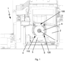
- Figure 1 shows a grinding machine 1 in a perspective that primarily allows a view into its processing area 2, in which the machining of the workpiece 3 to be machined takes place.
- the workpiece 3 is clamped in the workpiece carrier 4 so that it can rotate about its longitudinal axis, for example, which is arranged so that it can move on a carriage 5.
- the workpiece 3 is machined using the grinding wheel 6, which can be driven in both directions of rotation by means of a driven axis 7 and can be moved together with the driven axis 7 and the associated drive relative to the workpiece carrier 4 in several degrees of freedom.
- FIG. 1 A special feature of the Figure 1
- the main component of the grinding machine 1 shown is the cooling lubricant nozzle carrier 100, which is also described below with reference to the Figures 2 to 6 , which show different views of the cooling lubricant nozzle carrier 100, are explained in more detail.
- the cooling lubricant nozzle carrier 100 has, as in each of the Figures 2 to 6 can be seen, two cooling lubricant nozzles 110,120, which are each arranged in the end region of one of the two circular sector-shaped side legs 130,140.
- the circular sector-shaped side legs 130,140 are mounted on a central leg 150 in such a way that they are each movable in a plane that is perpendicular to the axis 7 of the grinding wheel 6 along a circular path, which can in particular be given by a center line of the circular sector-shaped side legs 130, 140.
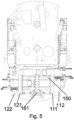
- the cooling lubricant nozzles 110,120 can be freely positioned around the grinding wheel 6 on a circular path, which can in particular run parallel to the circumference of the grinding wheel 6, wherein a particularly well-positioned Figure 5 recognizable offset of the circular sector-shaped side legs 130, 140 in the direction of the driven axis 7 to each other, it is ensured that in all positions a collision of the circular sector-shaped side legs 130,140 with each other is avoided.
- the spray heads 111,121 of the cooling lubricant nozzles 110,120 are fastened to holding sections 112,122 of the cooling lubricant nozzles 110,120, which have a different length adapted to the offset of the annular side legs 130,140.
- the holding sections 112, 122 in the interior of which the supply lines (not shown in the figures) also run, via which the spray heads 111, 121 are supplied with cooling lubricant, can in a preferred embodiment be connected via a bayonet lock to the circular sector-shaped side legs 130, 140 and supply lines for cooling lubricant arranged in or on them.
- a sealing element e.g. a sealing ring
- connection production and release of the connection can be carried out in an automated manner simply by using a robot arm or in the pick-up method carried out by the grinding spindle, for example when the grinding wheel 6 is changed and therefore spray heads 111,121 with a different shape are desired.
- Cooling lubricant nozzles 110,120 In the end region of the holding sections 112,122 of the Cooling lubricant nozzles 110,120 also have external gearing 113,123. This external gearing enables rotation of the cooling lubricant nozzles 110,120 by means of driven gear segments 132,142, so that the direction in which the spray heads 111,121 spray can be adjusted or adjusted. In this way, for example, a shifting grinding point, e.g. as a result of wear of the grinding wheel 6, can be easily compensated.
- the gear segments 132, 142 are provided with a guide slot 132a, 142a into which pins or screws 130a, 140a engage, so that the gear segments 132, 142 can be displaced on the respective circular sector-shaped side leg 130, 140 in such a way that a section with internal toothing 132b, 142b interacting with the respective external toothing 113, 123 causes the holding section 112, 122 to rotate.
- This displacement is driven by motors 155,156 arranged on the center leg, which interact with an external toothing 132c,142c of the racks 132,142 via gear wheel arrangements 157,158 and which receive their travel commands from a control system of the grinding machine in order to automatically move the cooling lubricant nozzles 110,120 and bring them into the desired position.
- the circular sector-shaped side legs 130,140 each have an external toothing 131,141. This makes it possible to drive the circular sector-shaped side legs 130,140 each via pinions 151,152 or, if required, via a gear with (gear) motors 153,154 arranged on the middle leg 150, which receive their driving commands from a control system of the grinding machine. received, automatically moved and brought into the desired position.
- the drives, in particular the (gear) motors, and the cooling lubricant supply are designed in such a way that the nozzles can be adjusted during operation, in particular at a cooling lubricant pressure of more than 30 bar and a cooling lubricant volume flow of 260 l/min.
- the cooling lubricant nozzles 110,120 can be moved independently of one another and in an automated manner, in particular CNC-controlled, due to these degrees of freedom of movement, so that one supplies cooling lubricant as a cooling nozzle for cooling the grinding point or workpiece in the direction of rotation of the wheel shortly before the current grinding point in order to avoid unacceptably high temperatures, while the other is used as an extinguishing nozzle for extinguishing/cooling sparks that have nevertheless occurred, which guides cooling lubricant past the grinding wheel after the grinding point in the opposite direction to the direction of rotation of the grinding wheel.
- the cooling lubricant nozzles 110,120, the line systems with which they are supplied with cooling lubricant and the control of the cooling lubricant supply with regard to pressure and throughput volume of the cooling lubricant are adapted so that each of the cooling lubricant nozzles 110,120 can be used both as a cooling and as an extinguishing nozzle, depending on the current direction of rotation of the grinding wheel 6. This design minimizes the risk of a collision with the workpiece, clamping device or other machine components.
- FIG. 1 In the embodiment of the cooling lubricant nozzle carrier 100 shown in FIG. 1, a further cooling lubricant nozzle 160 is present, namely the one shown in FIG. Figure 3 Particularly clearly visible is the flushing nozzle, which is fixed to the middle leg 150 of the cooling lubricant nozzle carrier, whose spray pattern is controlled by a replaceable nozzle plate 161, which can be Figure 5 can be influenced particularly well.
- the flushing nozzle is typically operated with higher coolant pressure, for example 70 bar, and lower coolant volume flows, for example 30 l/min, than the cooling and extinguishing nozzles.
Landscapes
- Engineering & Computer Science (AREA)
- Mechanical Engineering (AREA)
- Grinding-Machine Dressing And Accessory Apparatuses (AREA)
Claims (17)
- Porte-buses de lubrifiant de refroidissement (100) pour une rectifieuse (1),- le porte-buse de lubrifiant de refroidissement (100) a une branche médiane (150) et deux branches latérales (130, 140) installées sur cette branche médiane (150), de manière mobile par rapport à la branche médiane (150),- le porte-buses de lubrifiant de refroidissement (100) comporte au moins deux buses de lubrifiant de refroidissement (110, 120) dont au moins l'une est installée sur chacune des branches latérales (130, 140),- les branches latérales (130, 140) étant montées mobiles respectivement par rapport à la branche médiane (150) de façon que les buses de lubrifiant de refroidissement (110, 120) installées sur la branche latérale (130, 140) respective, puissent se déplacer lors du déplacement de la branche latérale correspondante (130, 140) en commun avec la branche latérale (130, 140) sur un segment de la trajectoire circulaire,porte-buses caractérisé en ce queles branches latérales (130, 140) sont décalées l'une par rapport à l'autre par rapport à l'axe médian de la trajectoire circulaire sur laquelle se déplacent en commun des buses de lubrifiant de refroidissement (110, 120) lors du mouvement de la branche latérale respective (130, 140) en commun avec les branches latérales (130, 140).
- Porte-buses de lubrifiant de refroidissement (100) selon la revendication 1,
caractérisé en ce que
les branches latérales (130, 140) sont entraînées par un moyen d'entraînement de façon à pouvoir être déplacées indépendamment. - Porte-buses de lubrifiant de refroidissement (100) selon la revendication 1 ou 2,
caractérisé en ce que
au moins une buse de lubrifiant de refroidissement (110, 120) est entraînée par un moteur (155, 156) de façon à pouvoir pivoter séparément. - Porte-buses de lubrifiant de refroidissement (100) selon la revendication 3,
caractérisé en ce que
la buse de lubrifiant de refroidissement (110, 120) entraînée par le moteur (155, 156) peut pivoter grâce à une denture extérieure (113, 123) qui coopère avec une crémaillère (132b, 142b) d'un segment déplacé par le moteur (155, 156) sur un demi-segment (112, 122) de la buse de lubrifiant de refroidissement (110, 120). - Porte-buses de lubrifiant de refroidissement (100) selon l'une des revendications 1 à 4,
caractérisé en ce que
les buses de lubrifiant de refroidissement (130, 140) sont remplaçables. - Porte-buses de lubrifiant de refroidissement (100) selon la revendication 5,
caractérisé en ce que
les buses de lubrifiant de refroidissement (110, 120) sont fixées à la branche latérale (130, 140) par un raccord baïonnette. - Porte-buses de lubrifiant de refroidissement (100) selon l'une des revendications 1 à 6,
caractérisé par
une autre buse de lubrifiant de refroidissement (160) sur la branche médiane (150). - Porte-buses de lubrifiant de refroidissement (100) selon la revendication 7,
caractérisé en ce que
l'autre buse de lubrifiant de refroidissement (160) comporte une plaque de buse (161) remplaçable. - Porte-buses de lubrifiant de refroidissement (100) selon l'une des revendications 1 à 8,
caractérisé en ce que
les branches latérales (130, 140) sont en forme de secteur d'anneau de cercle. - Rectifieuse (1) comportant une commande, un support de pièce (4) pour recevoir une pièce (3) à usiner et un disque de meulage porté par un axe entraîné (7),
rectifieuse (1) caractérisée en ce qu'elle en outre comporte un porte-buses de lubrifiant de refroidissement (100) selon l'une des revendications 1 à 10. - Rectifieuse (1) selon la revendication 10,
caractérisée en ce quela commande est conçue et installée pour utiliser deux buses de lubrifiant de refroidissement (110, 120) installées sur des branches latérales (130, 140) différentes, soit comme buses de refroidissement pour refroidir le point de rectification et/ou la pièce par la fourniture de lubrifiant de refroidissement dans le sens de rotation du disque juste en amont du point de rectification actuel, oucomme buse d'extinction pour éteindre et/ou refroidir les étincelles formées, qui sont entraînées dans le sens opposé au sens de rotation du disque de rectifieuse en aval du point de rectification, le lubrifiant de refroidissement passant à proximité du disque de meule. - Rectifieuse (1) selon la revendication 10 ou 11,
caractérisée en ce que
la commande est conçue et installée pour modifier la position des buses de lubrifiant de refroidissement (110, 120) en cours de fonctionnement. - Rectifieuse (1) selon l'une des revendications 10 à 12,
caractérisé en ce qu'
elle a un dispositif pour changer automatiquement les buses de lubrifiant (110, 120). - Rectifieuse (1) selon l'une des revendications 10 à 13,
caractérisé en ce que
la branche médiane (150) est formée par une partie de la rectifieuse (1), notamment par la console d'une broche de la rectifieuse (1). - Procédé de gestion d'une rectifieuse (1) selon l'une des revendications 10 à 14,
selon lequelon utilise une buse de lubrifiant de refroidissement (110, 120) comme buse de refroidissement pour refroidir le point de rectification et/ou la pièce par la fourniture de lubrifiant de refroidissement dans le sens de rotation du disque, juste en amont du point de rectification actuel, et une buse de lubrifiant de refroidissement (120, 110) comme buse d'extinction pour éteindre et/ou refroidir les étincelles dégagées qui passent dans le sens opposé au sens de rotation du disque de rectifieuse, après le point de meulage, pour le lubrifiant passe près du disque de meulage, procédé caractérisé en ce quele meulage, on déplace au moins l'une des buses de lubrifiant de refroidissement (110, 120) sur un segment d'une trajectoire circulaire. - Procédé selon la revendication 15,
caractérisé en ce que
au moins une fois pendant la rectification, on change le sens de rotation du disque de meule (6) et ainsi on échange le rôle des buses de lubrifiant (110, 120). - Procédé selon la revendication 15 ou 16,
caractérisé en ce que
au moins une fois pendant la rectification, on fait tourner les buses de lubrifiant de refroidissement (110, 120) par rapport aux branches latérales (130, 140) auxquelles elles sont fixées.
Applications Claiming Priority (1)
| Application Number | Priority Date | Filing Date | Title |
|---|---|---|---|
| DE102021126504.5A DE102021126504A1 (de) | 2021-10-13 | 2021-10-13 | Kühlschmierstoffdüsenträger für eine Schleifmaschine, Schleifmaschine mit einem solchen Kühlschmierstoffdüsenträger und Verfahren zum Betrieb eines Kühlschmierstoffdüsenträgers |
Publications (2)
| Publication Number | Publication Date |
|---|---|
| EP4166276A1 EP4166276A1 (fr) | 2023-04-19 |
| EP4166276B1 true EP4166276B1 (fr) | 2024-12-18 |
Family
ID=82786686
Family Applications (1)
| Application Number | Title | Priority Date | Filing Date |
|---|---|---|---|
| EP22188015.6A Active EP4166276B1 (fr) | 2021-10-13 | 2022-08-01 | Porte-buse de lubrifiant à basse température pour une machine à rectifier, machine à rectifier dotée d'un tel porte-buse de lubrifiant à basse température et procédé permettant de faire fonctionner un porte-buse de lubrifiant à basse température |
Country Status (3)
| Country | Link |
|---|---|
| US (1) | US12403562B2 (fr) |
| EP (1) | EP4166276B1 (fr) |
| DE (1) | DE102021126504A1 (fr) |
Families Citing this family (1)
| Publication number | Priority date | Publication date | Assignee | Title |
|---|---|---|---|---|
| WO2025038459A1 (fr) * | 2023-08-14 | 2025-02-20 | Fusion Coolant Systems, Inc. | Systèmes et procédés de distribution commandée de fluide d'usinage |
Family Cites Families (16)
| Publication number | Priority date | Publication date | Assignee | Title |
|---|---|---|---|---|
| US2534941A (en) * | 1948-01-16 | 1950-12-19 | Thompson Grinder Co | Method and apparatus for grinding |
| US4679970A (en) * | 1981-08-26 | 1987-07-14 | Kearney & Trecker Corporation | High speed toolholder for a machining center |
| US4619081A (en) * | 1985-02-28 | 1986-10-28 | General Signal Corporation | Combined nozzle with air foil |
| US4822218A (en) * | 1986-03-31 | 1989-04-18 | Yoshikazu Satoh | Fluid delivery device for a machining center, and a machining center |
| US4929130A (en) * | 1989-06-28 | 1990-05-29 | United Technologies Corporation | Grinding wheel guard apparatus |
| DE20005648U1 (de) | 2000-03-20 | 2000-05-25 | August Heinr. Schmidt GmbH & Co KG Maschinenfabrik, 70469 Stuttgart | Schwenkantrieb einer mit Düsen versehenen Kühlmittelzufuhr an einer Kreissägeblattschleifmaschine |
| DE102006037434B4 (de) * | 2006-08-09 | 2009-04-02 | Haas Schleifmaschinen Gmbh | Werkzeugmaschine |
| DE102009043677A1 (de) | 2009-10-01 | 2011-04-14 | Kapp Gmbh | Hartfeinbearbeitungsmaschine zum Hartfeinbearbeiten eines Werkstücks |
| DE102010026777A1 (de) | 2010-07-09 | 2012-01-12 | Haas Schleifmaschinen Gmbh | Schleifmaschine |
| DE102012104263A1 (de) * | 2012-05-16 | 2013-11-21 | Walter Maschinenbau Gmbh | Kühlmittelverteiler für eine Werkzeugmaschine |
| US9796060B2 (en) * | 2012-08-28 | 2017-10-24 | The Gleason Works | Quick-change fluid supply apparatus for machining |
| JP2015051478A (ja) * | 2013-09-06 | 2015-03-19 | コマツNtc株式会社 | 計測装置及びその計測装置を備えた研削盤 |
| JP6625795B2 (ja) * | 2014-09-30 | 2019-12-25 | ファナック株式会社 | 切削液噴射装置 |
| EP3208037B1 (fr) | 2016-02-22 | 2019-05-08 | ISOG Technology GmbH | Support de tuyère pur une affûteuse d' outils |
| DE102016012904A1 (de) | 2016-10-26 | 2018-04-26 | Gebr. Saacke Gmbh & Co. Kg | Kühlmittelzuführung für eine Werkzeugmaschine, insbesondere eine Schleifmaschine |
| DE102019006362A1 (de) | 2019-09-09 | 2021-03-11 | VolImer Werke Maschinenfabrik GmbH | Vorrichtung zum Zuführen eines Mediums zu einem Werkzeug einer Bearbeitungsmaschine und Verfahren zum Bereitstellen einer derartigen Vorrichtung |
-
2021
- 2021-10-13 DE DE102021126504.5A patent/DE102021126504A1/de active Pending
-
2022
- 2022-08-01 EP EP22188015.6A patent/EP4166276B1/fr active Active
- 2022-10-07 US US17/961,881 patent/US12403562B2/en active Active
Also Published As
| Publication number | Publication date |
|---|---|
| US20230115142A1 (en) | 2023-04-13 |
| EP4166276A1 (fr) | 2023-04-19 |
| US12403562B2 (en) | 2025-09-02 |
| DE102021126504A1 (de) | 2023-04-13 |
Similar Documents
| Publication | Publication Date | Title |
|---|---|---|
| DE112008000549B4 (de) | Numerisch gesteuerte Maschine und Verfahren zur Anwendung eines Kühlmittels | |
| DE69026068T2 (de) | Handhabungsgerät, vorgesehen für das Zusammenwirken mit einem Industrieroboter | |
| DE10029967B4 (de) | Vorrichtung zur Bearbeitung von optischen Werkstücken | |
| DE2535135C2 (fr) | ||
| EP2404704B1 (fr) | Affûteuse avec une buse de refroidissement réglable monté sur le capot de protection | |
| EP0958884A1 (fr) | Procédé d'usinage de pièces ainsi que machine-outil | |
| EP2308638B1 (fr) | Machine de traitement dur et fin pour le traitement dur et fin d'une pièce usinée | |
| EP3463744B1 (fr) | Machine d'usinage laser avec un changeur de buses et une enceinte de protection | |
| EP0491242A1 (fr) | Machine-outil pour l'usinage abrasif de pièces au moyen d'un faisceau laser | |
| EP3894128B1 (fr) | Machine de traitement de tuyaux pour couper des tuyaux ou des profils par faisceau laser | |
| EP2732895B1 (fr) | Machine-outil pour la fabrication de profilés | |
| DE4101749A1 (de) | Fahrbare stahlrohr-fraesschneidemaschine | |
| EP2308627B1 (fr) | Machine de traitement dur et fin pour le traitement dur et fin d'une pièce usinée | |
| DE112015002391T5 (de) | Werkzeugmaschine | |
| WO2017220160A1 (fr) | Unité d'usinage pour usiner une pièce au moyen d'un faisceau d'usinage thermique, comprenant un dispositif d'accouplement | |
| DE4229423A1 (de) | Drehmaschine | |
| EP1574273B1 (fr) | Tour | |
| EP3853415B1 (fr) | Dispositif servant à reprofiler et ébarber des rails | |
| EP4166276A1 (fr) | Porte-buse de lubrifiant à basse température pour une machine à rectifier, machine à rectifier dotée d'un tel porte-buse de lubrifiant à basse température et procédé permettant de faire fonctionner un porte-buse de lubrifiant à basse température | |
| WO2018055183A1 (fr) | Outil et machine-outil et procédé de traitement de pièces en forme de plaques | |
| WO1984001737A1 (fr) | Machine-outil | |
| CH714436B1 (de) | Verfahren zur Verzahnbearbeitung eines Werkstücks mit einem Werkzeug, wobei während der Verzahnbearbeitung mittels einer Kühlmitteldüse Kühlmittel auf das Werkzeug aufgebracht wird. | |
| EP0453875B2 (fr) | Machine pour le travail du métal par enlèvement de copeaux | |
| AT505069B1 (de) | Werkzeugrevolver | |
| EP3829813B1 (fr) | Dispositif et procédé destinés à traiter une pièce à usiner, en particulier une pièce à usiner pourvue de lames, au moyen d'un outil d'abrasion ou d'érosion |
Legal Events
| Date | Code | Title | Description |
|---|---|---|---|
| PUAI | Public reference made under article 153(3) epc to a published international application that has entered the european phase |
Free format text: ORIGINAL CODE: 0009012 |
|
| STAA | Information on the status of an ep patent application or granted ep patent |
Free format text: STATUS: THE APPLICATION HAS BEEN PUBLISHED |
|
| AK | Designated contracting states |
Kind code of ref document: A1 Designated state(s): AL AT BE BG CH CY CZ DE DK EE ES FI FR GB GR HR HU IE IS IT LI LT LU LV MC MK MT NL NO PL PT RO RS SE SI SK SM TR |
|
| STAA | Information on the status of an ep patent application or granted ep patent |
Free format text: STATUS: REQUEST FOR EXAMINATION WAS MADE |
|
| 17P | Request for examination filed |
Effective date: 20231006 |
|
| RBV | Designated contracting states (corrected) |
Designated state(s): AL AT BE BG CH CY CZ DE DK EE ES FI FR GB GR HR HU IE IS IT LI LT LU LV MC MK MT NL NO PL PT RO RS SE SI SK SM TR |
|
| GRAP | Despatch of communication of intention to grant a patent |
Free format text: ORIGINAL CODE: EPIDOSNIGR1 |
|
| STAA | Information on the status of an ep patent application or granted ep patent |
Free format text: STATUS: GRANT OF PATENT IS INTENDED |
|
| GRAS | Grant fee paid |
Free format text: ORIGINAL CODE: EPIDOSNIGR3 |
|
| INTG | Intention to grant announced |
Effective date: 20241010 |
|
| GRAA | (expected) grant |
Free format text: ORIGINAL CODE: 0009210 |
|
| STAA | Information on the status of an ep patent application or granted ep patent |
Free format text: STATUS: THE PATENT HAS BEEN GRANTED |
|
| AK | Designated contracting states |
Kind code of ref document: B1 Designated state(s): AL AT BE BG CH CY CZ DE DK EE ES FI FR GB GR HR HU IE IS IT LI LT LU LV MC MK MT NL NO PL PT RO RS SE SI SK SM TR |
|
| REG | Reference to a national code |
Ref country code: CH Ref legal event code: EP |
|
| REG | Reference to a national code |
Ref country code: DE Ref legal event code: R096 Ref document number: 502022002420 Country of ref document: DE |
|
| REG | Reference to a national code |
Ref country code: IE Ref legal event code: FG4D Free format text: LANGUAGE OF EP DOCUMENT: GERMAN |
|
| REG | Reference to a national code |
Ref country code: LT Ref legal event code: MG9D |
|
| PG25 | Lapsed in a contracting state [announced via postgrant information from national office to epo] |
Ref country code: HR Free format text: LAPSE BECAUSE OF FAILURE TO SUBMIT A TRANSLATION OF THE DESCRIPTION OR TO PAY THE FEE WITHIN THE PRESCRIBED TIME-LIMIT Effective date: 20241218 |
|
| PG25 | Lapsed in a contracting state [announced via postgrant information from national office to epo] |
Ref country code: FI Free format text: LAPSE BECAUSE OF FAILURE TO SUBMIT A TRANSLATION OF THE DESCRIPTION OR TO PAY THE FEE WITHIN THE PRESCRIBED TIME-LIMIT Effective date: 20241218 |
|
| PG25 | Lapsed in a contracting state [announced via postgrant information from national office to epo] |
Ref country code: BG Free format text: LAPSE BECAUSE OF FAILURE TO SUBMIT A TRANSLATION OF THE DESCRIPTION OR TO PAY THE FEE WITHIN THE PRESCRIBED TIME-LIMIT Effective date: 20241218 |
|
| PG25 | Lapsed in a contracting state [announced via postgrant information from national office to epo] |
Ref country code: NO Free format text: LAPSE BECAUSE OF FAILURE TO SUBMIT A TRANSLATION OF THE DESCRIPTION OR TO PAY THE FEE WITHIN THE PRESCRIBED TIME-LIMIT Effective date: 20250318 |
|
| REG | Reference to a national code |
Ref country code: NL Ref legal event code: MP Effective date: 20241218 |
|
| PG25 | Lapsed in a contracting state [announced via postgrant information from national office to epo] |
Ref country code: LV Free format text: LAPSE BECAUSE OF FAILURE TO SUBMIT A TRANSLATION OF THE DESCRIPTION OR TO PAY THE FEE WITHIN THE PRESCRIBED TIME-LIMIT Effective date: 20241218 Ref country code: GR Free format text: LAPSE BECAUSE OF FAILURE TO SUBMIT A TRANSLATION OF THE DESCRIPTION OR TO PAY THE FEE WITHIN THE PRESCRIBED TIME-LIMIT Effective date: 20250319 |
|
| PG25 | Lapsed in a contracting state [announced via postgrant information from national office to epo] |
Ref country code: RS Free format text: LAPSE BECAUSE OF FAILURE TO SUBMIT A TRANSLATION OF THE DESCRIPTION OR TO PAY THE FEE WITHIN THE PRESCRIBED TIME-LIMIT Effective date: 20250318 |
|
| PG25 | Lapsed in a contracting state [announced via postgrant information from national office to epo] |
Ref country code: NL Free format text: LAPSE BECAUSE OF FAILURE TO SUBMIT A TRANSLATION OF THE DESCRIPTION OR TO PAY THE FEE WITHIN THE PRESCRIBED TIME-LIMIT Effective date: 20241218 |
|
| PG25 | Lapsed in a contracting state [announced via postgrant information from national office to epo] |
Ref country code: SM Free format text: LAPSE BECAUSE OF FAILURE TO SUBMIT A TRANSLATION OF THE DESCRIPTION OR TO PAY THE FEE WITHIN THE PRESCRIBED TIME-LIMIT Effective date: 20241218 |
|
| PG25 | Lapsed in a contracting state [announced via postgrant information from national office to epo] |
Ref country code: PL Free format text: LAPSE BECAUSE OF FAILURE TO SUBMIT A TRANSLATION OF THE DESCRIPTION OR TO PAY THE FEE WITHIN THE PRESCRIBED TIME-LIMIT Effective date: 20241218 |
|
| PG25 | Lapsed in a contracting state [announced via postgrant information from national office to epo] |
Ref country code: ES Free format text: LAPSE BECAUSE OF FAILURE TO SUBMIT A TRANSLATION OF THE DESCRIPTION OR TO PAY THE FEE WITHIN THE PRESCRIBED TIME-LIMIT Effective date: 20241218 |
|
| PG25 | Lapsed in a contracting state [announced via postgrant information from national office to epo] |
Ref country code: IS Free format text: LAPSE BECAUSE OF FAILURE TO SUBMIT A TRANSLATION OF THE DESCRIPTION OR TO PAY THE FEE WITHIN THE PRESCRIBED TIME-LIMIT Effective date: 20250418 |
|
| PG25 | Lapsed in a contracting state [announced via postgrant information from national office to epo] |
Ref country code: PT Free format text: LAPSE BECAUSE OF FAILURE TO SUBMIT A TRANSLATION OF THE DESCRIPTION OR TO PAY THE FEE WITHIN THE PRESCRIBED TIME-LIMIT Effective date: 20250421 |
|
| PG25 | Lapsed in a contracting state [announced via postgrant information from national office to epo] |
Ref country code: EE Free format text: LAPSE BECAUSE OF FAILURE TO SUBMIT A TRANSLATION OF THE DESCRIPTION OR TO PAY THE FEE WITHIN THE PRESCRIBED TIME-LIMIT Effective date: 20241218 |
|
| PG25 | Lapsed in a contracting state [announced via postgrant information from national office to epo] |
Ref country code: RO Free format text: LAPSE BECAUSE OF FAILURE TO SUBMIT A TRANSLATION OF THE DESCRIPTION OR TO PAY THE FEE WITHIN THE PRESCRIBED TIME-LIMIT Effective date: 20241218 |
|
| PG25 | Lapsed in a contracting state [announced via postgrant information from national office to epo] |
Ref country code: SK Free format text: LAPSE BECAUSE OF FAILURE TO SUBMIT A TRANSLATION OF THE DESCRIPTION OR TO PAY THE FEE WITHIN THE PRESCRIBED TIME-LIMIT Effective date: 20241218 |
|
| PG25 | Lapsed in a contracting state [announced via postgrant information from national office to epo] |
Ref country code: SE Free format text: LAPSE BECAUSE OF FAILURE TO SUBMIT A TRANSLATION OF THE DESCRIPTION OR TO PAY THE FEE WITHIN THE PRESCRIBED TIME-LIMIT Effective date: 20241218 |
|
| REG | Reference to a national code |
Ref country code: DE Ref legal event code: R097 Ref document number: 502022002420 Country of ref document: DE |
|
| PG25 | Lapsed in a contracting state [announced via postgrant information from national office to epo] |
Ref country code: DK Free format text: LAPSE BECAUSE OF FAILURE TO SUBMIT A TRANSLATION OF THE DESCRIPTION OR TO PAY THE FEE WITHIN THE PRESCRIBED TIME-LIMIT Effective date: 20241218 |
|
| PGFP | Annual fee paid to national office [announced via postgrant information from national office to epo] |
Ref country code: DE Payment date: 20250922 Year of fee payment: 4 |
|
| PGFP | Annual fee paid to national office [announced via postgrant information from national office to epo] |
Ref country code: IT Payment date: 20250901 Year of fee payment: 4 |
|
| PGFP | Annual fee paid to national office [announced via postgrant information from national office to epo] |
Ref country code: AT Payment date: 20251020 Year of fee payment: 4 Ref country code: FR Payment date: 20250821 Year of fee payment: 4 |
|
| PGFP | Annual fee paid to national office [announced via postgrant information from national office to epo] |
Ref country code: CH Payment date: 20250901 Year of fee payment: 4 |
|
| PGFP | Annual fee paid to national office [announced via postgrant information from national office to epo] |
Ref country code: CZ Payment date: 20250722 Year of fee payment: 4 |
|
| PLBE | No opposition filed within time limit |
Free format text: ORIGINAL CODE: 0009261 |
|
| STAA | Information on the status of an ep patent application or granted ep patent |
Free format text: STATUS: NO OPPOSITION FILED WITHIN TIME LIMIT |
|
| 26N | No opposition filed |
Effective date: 20250919 |
|
| PG25 | Lapsed in a contracting state [announced via postgrant information from national office to epo] |
Ref country code: MC Free format text: LAPSE BECAUSE OF FAILURE TO SUBMIT A TRANSLATION OF THE DESCRIPTION OR TO PAY THE FEE WITHIN THE PRESCRIBED TIME-LIMIT Effective date: 20241218 |
|
| PG25 | Lapsed in a contracting state [announced via postgrant information from national office to epo] |
Ref country code: LU Free format text: LAPSE BECAUSE OF NON-PAYMENT OF DUE FEES Effective date: 20250801 |