EP4166310B1 - Procédé et dispositif de préparation de la surface de la carcasse d'un pneumatique de véhicule automobile en cours de son rechapage - Google Patents
Procédé et dispositif de préparation de la surface de la carcasse d'un pneumatique de véhicule automobile en cours de son rechapage Download PDFInfo
- Publication number
- EP4166310B1 EP4166310B1 EP21202352.7A EP21202352A EP4166310B1 EP 4166310 B1 EP4166310 B1 EP 4166310B1 EP 21202352 A EP21202352 A EP 21202352A EP 4166310 B1 EP4166310 B1 EP 4166310B1
- Authority
- EP
- European Patent Office
- Prior art keywords
- carcass
- pneumatic vehicle
- robot
- vehicle tyre
- surface damage
- Prior art date
- Legal status (The legal status is an assumption and is not a legal conclusion. Google has not performed a legal analysis and makes no representation as to the accuracy of the status listed.)
- Active
Links
Images
Classifications
-
- B—PERFORMING OPERATIONS; TRANSPORTING
- B29—WORKING OF PLASTICS; WORKING OF SUBSTANCES IN A PLASTIC STATE IN GENERAL
- B29D—PRODUCING PARTICULAR ARTICLES FROM PLASTICS OR FROM SUBSTANCES IN A PLASTIC STATE
- B29D30/00—Producing pneumatic or solid tyres or parts thereof
- B29D30/06—Pneumatic tyres or parts thereof (e.g. produced by casting, moulding, compression moulding, injection moulding, centrifugal casting)
- B29D30/52—Unvulcanised treads, e.g. on used tyres; Retreading
- B29D30/54—Retreading
- B29D2030/541—Abrading the tyre, e.g. buffing, to remove tread and/or sidewalls rubber, to prepare it for retreading
-
- B—PERFORMING OPERATIONS; TRANSPORTING
- B29—WORKING OF PLASTICS; WORKING OF SUBSTANCES IN A PLASTIC STATE IN GENERAL
- B29D—PRODUCING PARTICULAR ARTICLES FROM PLASTICS OR FROM SUBSTANCES IN A PLASTIC STATE
- B29D30/00—Producing pneumatic or solid tyres or parts thereof
- B29D30/06—Pneumatic tyres or parts thereof (e.g. produced by casting, moulding, compression moulding, injection moulding, centrifugal casting)
- B29D30/52—Unvulcanised treads, e.g. on used tyres; Retreading
- B29D30/54—Retreading
- B29D2030/546—Measuring, detecting, monitoring, inspecting, controlling
Definitions
- the invention relates to a method for preparing the surface of the carcass of a pneumatic vehicle tire during retreading thereof, comprising the steps of removing the tread and the sidewall of the pneumatic vehicle tire while exposing the carcass and clamping the pneumatic vehicle tire onto a rotatable hub and then searching the exposed surface of the carcass for surface damage during rotation of the pneumatic vehicle tire, wherein if surface damage is found, the rotation of the pneumatic vehicle tire is temporarily stopped and the identified surface damage is removed by means of a grinding tool guided by a robot, creating a depression in the surface of the carcass, and then the rotation of the pneumatic vehicle tire and the searching of the surface for surface damage are continued until one complete rotation of the pneumatic vehicle tire on the rotatable hub has been completed and the surface damage has been removed.
- the invention further relates to a corresponding device for preparing the surface of the carcass of a pneumatic vehicle tire during retreading thereof, comprising a rotatable hub on which a pneumatic vehicle tire with a carcass exposed by removing treads and sidewalls can be clamped and searched for surface damage during rotation of the pneumatic vehicle tire, as well as a grinding tool guided by a robot for grinding out the identified surface damage while creating a depression in the surface of the carcass.
- Pneumatic vehicle tyres for trucks, passenger cars and delivery vans which are eligible for retreading after reaching the wear limit usually have a worn profile in the area of the tread and possibly damaged sidewalls, which are mechanically removed in order to expose the carcass of the pneumatic vehicle tyre, onto which a new Treads and sidewalls can be applied. This can be done, for example, in the form of raw or pre-vulcanized rubber strips applied to the carcass, which are then cured in a vulcanization process and bonded to the carcass underneath.
- the surfaces of the carcass in the area of the crown, sidewalls and bead areas are subjected to a grinding process, which is usually carried out manually or by hand, in order to remove any surface damage in the carcass before a new tread is placed in the area of the crown of the carcass and connected to it.
- a manual grinding process is carried out by an experienced operator who uses a trained eye to search the carcass for surface damage and then grinds down or removes the surface damage found using various grinding tools and prepares it for the upcoming covering with a new rubber strip. This creates depressions in the carcass which are filled in a subsequent step.
- Such a manual grinding process is complex, prone to errors and requires carefully working and trained personnel, with large quantities of rubber and metal particles that are hazardous to health being released during the processing of the surface damage.
- the disadvantage of these known automatic grinding devices is that, despite the arrangement of corresponding sensors, they cannot reliably prevent the steel belt inside the carcass from being damaged when the grinding tool is used, since the large number of different types of pneumatic vehicle tires from different manufacturers have a wide range of positioning and structure of the steel belts used.
- the known automatic grinding devices are not able to to treat the surface area adjacent to the sidewall and/or the bead area of the exposed carcass.
- the object of the invention is therefore to propose a method and a device of the type mentioned at the outset which overcomes the disadvantages of the prior art by reliably preventing damage to the steel belts and by enabling the surface areas of the carcass to be processed automatically over as much of the surface area as possible.
- a device for solving the problem is the subject of patent claim 6.
- the method proposed within the scope of the invention provides that a database with specific data of the carcasses of pneumatic vehicle tires according to tire type and manufacturer is provided, which includes at least the position and dimensions of a steel belt in the carcass.
- the specific data of the carcass of this pneumatic vehicle tire are read from the database and transmitted to the robot so that its control system grinds out the surface damage using the grinding tool guided by the robot only at such positions and to such a depth that the existing steel belt is not exposed.
- the database proposed according to the invention can, in the form of a tire management system, contain the necessary data of the carcass of each directory sorted by tire type and manufacturer and transmit this data to the robot that guides the grinding tool.
- the inventive The database can therefore be part of the robot's control system or it can be provided separately from the robot and connected to it via appropriate communication means.
- the depth of the steel belt in relation to the surface of the carcass and the thickness of the carcass is also determined, which can be done for example using appropriate sensors or using values that are also stored in the database and read out accordingly.
- the depth of the grinding removal to be made is then calculated from these data without reaching the steel belt and this depth is transmitted to the robot control system in order to carry out the grinding up to a maximum of the calculated depth.
- the surface of the carcass can be scanned using a two-dimensional profilometer, as is commercially available.
- profilometers include tactile sensors or non-contact, preferably optical profilometers, which work, for example, using confocal technology, laser beams or white light interferometry.
- Such a profilometer and any other sensors can advantageously be attached to the robot parallel to the grinding tool and brought within reach of the vehicle pneumatic tire to be checked for surface damage.
- the robot which carries the grinding tool and, if applicable, the profilometer and is connected to the database, is preferably designed as a 5-axis robot in order to ensure sufficient mobility of the grinding tools and the profilometer guided by it.
- the surface area of the carcass facing the tread is searched for surface damage and this is removed in the manner described.
- the surface areas of the carcass facing the side walls and/or the bead area can also be searched for surface damage and this can be removed in the manner described above.
- the rotation is interrupted and stopped as soon as surface damage is detected, which is then removed with the pneumatic vehicle tire stationary in the manner already described.
- the rotation of the pneumatic vehicle tire is then continued until the next surface damage is detected and removed or the complete rotation of the pneumatic vehicle tire on the rotating hub has been completed so that all surface damage is removed.
- the person skilled in the art will recognize that it is also fundamentally possible to initially only determine the position and number of surface damages during a complete rotation of the pneumatic vehicle tire and to control the detected surface damages one after the other in a subsequent further rotation and to grind them out using the robot in the manner described.
- the device proposed within the scope of the invention for preparing the surface of the carcass of a pneumatic vehicle tire comprises, in addition to the rotatable hub, the scanning device and the grinding tool guided by the robot for grinding out the identified surface damage on the carcass of the pneumatic vehicle tire, a database that includes specific data of the carcasses of different pneumatic vehicle tires, divided by tire type and manufacturer, and contains at least the position and dimensions of the respective steel belt in the carcass.
- the specific data of the carcass of a pneumatic vehicle tire that is specifically placed on the rotatable hub and is to be prepared for retreading are read out from the database according to the invention and transmitted to the robot in order to enable the robot to grind out the surface damage using the Grinding of the grinding tool should only be carried out in positions and at such a depth that the steel belt is not exposed.
- the scanning device can be designed to determine the depth of the steel belt in relation to the surface of the carcass and the thickness of the carcass at the position of the surface damage, or such data are also stored in the database.
- the scanning device of the device according to the invention can, for example, be formed by a 2-dimensional profilometer.
- the device is supplemented by a handling robot with a robot-guided gripper that can place the vehicle pneumatic tire on the rotating hub and remove it from it.
- the robot-guided gripper can also be based on a suitable 5-axis robot that forms the handling robot.
- the surface area of the carcass facing the tread and the side walls can be searched using the scanning device and processed by the robot's grinding tool, and the pneumatic vehicle tire can then be positioned within reach of the scanning device and the grinding tool using the handling robot and its gripper for the bead areas to be searched and processed. Consequently, the crown and side walls of the pneumatic vehicle tire are searched and processed while it is mounted on the rotating hub, and the bead areas of the carcass are searched and processed using the handling robot and the pneumatic vehicle tire removed from the rotating hub and held in the gripper.
- the handling robot positions and guides the pneumatic vehicle tire past the scanning device and the grinding tool of the other robot so that any surface damage that has been identified can be searched and processed.
- the pneumatic vehicle tire is ejected, for example by means of the robot-guided gripper, and handed over to an operator who can carry out a manual follow-up inspection and, if necessary, manual rework, for example the removal of rust and the repair of holes and/or punctures in the carcass.
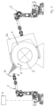
- the single figure shows a schematic representation of two robots 3, 5, each designed as a 5-axis robot and in the representation according to Figure 1 are arranged opposite one another.
- the robot 3 guides, among other things, a grinding tool 30 in the manner described below, while the robot 5 is equipped as a handling robot with a gripper 50 for a vehicle pneumatic tire 1.
- a known rotatable hub 2 with clamping means not shown in detail onto which a pneumatic vehicle tire 1 can be mounted after the worn tread and the side walls have been removed in a previous work step in a manner known per se and the carcass of the pneumatic vehicle tire 1 has been exposed.
- the application of the pneumatic vehicle tire 1 with exposed carcass to the rotatable hub 2 can be effected by the robot 5, which for this purpose carries and moves the gripper for gripping and manipulating the pneumatic vehicle tire 1.
- the pneumatic vehicle tire 1 After the pneumatic vehicle tire 1 has been applied, clamped and centered by the robot 5 on the rotatable hub 2 in the manner shown, the pneumatic vehicle tire can be rotated about its own axis, for example in the direction of rotation indicated by arrow R. It should be noted that the direction of rotation could equally be the opposite.
- the robot 3 arranged opposite the robot 5 carries at its free end the known grinding tool 30, for example a rotating grinding wheel, as well as a scanning device for the surface of the vehicle pneumatic tire 1 in the form of a 2-dimensional scanning profilometer 31.
- a database 4 is connected to the control device (not shown in detail) of the robot 3 guiding the grinding tool 30, in which specific data of the respective carcasses of pneumatic vehicle tires 1 are stored, sorted by tire type and manufacturer, which at least include the position and dimensioning of the steel belt in the respective carcass of the pneumatic vehicle tire 1.
- the corresponding data stored in the database 4 relating to this pneumatic vehicle tire 1 are retrieved by the control system of the robot 3 and taken into account in the subsequent control of the robot 3 in the manner described below.
- the profilometer 31 scans the surface, here the crown area of the carcass facing the removed tread, for possible surface damage.
- the control of the robot 3 uses the data read from the database 4 on the position and dimensions of the steel belt in the carcass and the determined damage pattern to calculate the depth and extent of the rubber material of the carcass to be removed by means of the grinding tool 30 in order to prepare the surface for later retreading.
- the depth of the steel belt and the prevailing thickness of the carcass i.e. the rubber material at the position of the surface damage, can be determined using appropriate sensors and included in the calculation.
- the robot 3 also has a detector for steel wires (not shown in detail). and a surface position sensor, which are also permanently attached to the arm of robot 3.
- the grinding tool 30 creates a crater or depression in the surface of the carcass by means of the robot 3, whereby only rubber material of the carcass is reliably removed without damaging the steel belt and the structural integrity of the carcass.
- the robot 3 brings the grinding tool 30 back to a distance from the surface of the carcass of the pneumatic vehicle tire 1 and the rotation of the same on the hub 2 as well as the scanning of the surface of the pneumatic vehicle tire by means of the profilometer 31 are continued until further surface damage is identified and processed in the manner already described or the pneumatic vehicle tire has completed a complete revolution on the rotatable hub 2 around its own axis, i.e. has rotated once through 360°, so that all surface damage has been identified and removed.
- the corresponding operation can then be carried out during a further run or revolution of the pneumatic vehicle tire 1 around its own axis on the hub 2 also in the area of both surface areas of the carcass of the pneumatic vehicle tire 1 facing the side walls in order to also search these areas for possible surface damage and to treat it.
- the pneumatic vehicle tire 1 can then be removed from the hub 2 again by means of the gripper 50 of the robot 5 and held in the gripper 50 and guided past the robot 3 so that the bead areas of the pneumatic vehicle tire 1 can also be examined for damage by means of the profilometer 31 and, if necessary, removed by means of the grinding tool 30.
- the pneumatic vehicle tire 1 can be transferred by the robot 5 to a downstream facility in which, for example, a manual follow-up inspection and/or manual reworking by an operator can be carried out, for example to remove rust and repair punctures and holes.
- the method and apparatus described above can be applied to all pneumatic vehicle tires that are to be retreaded, for example pneumatic vehicle tires for passenger cars, trucks and vans, and is suitable for both hot and cold retreading applications.
Landscapes
- Engineering & Computer Science (AREA)
- Mechanical Engineering (AREA)
- Tyre Moulding (AREA)
Claims (10)
- Procédé permettant de préparer la surface de la carcasse d'un pneu de véhicule (1) au cours du rechapage de celui-ci, comprenant les étapes consistant à retirer la bande de roulement et le flanc du pneu de véhicule (1) en dégageant la carcasse, et à installer le pneu de véhicule (1) sur un moyeu tournant (2), et à examiner ensuite la surface dégagée de la carcasse quant à des dommages de surface pendant une rotation du pneu de véhicule (1), dans lequel, si un dommage de surface est trouvé, la rotation du pneu de véhicule (1) est arrêtée momentanément, et le dommage de surface établi est retiré en créant un creux dans la surface de la carcasse au moyen d'un outil abrasif (30) guidé par un robot (3), et ensuite, la rotation du pneu de véhicule (1) et l'examen de la surface quant à des dommages de surface continuent jusqu'à qu'un tour complet du pneu de véhicule (1) sur le moyeu tournant (2) ait été réalisé et les dommages de surface aient été retirés, caractérisé en ce qu'une base de données (4) avec des données spécifiques des carcasses de pneus de véhicule (1) par type de pneu et fabricant est fournie qui comprend au moins la position et le dimensionnement d'une ceinture d'acier dans la carcasse, et avant l'examen de la surface dégagée du pneu de véhicule (1), les données spécifiques de la carcasse sont lues dans la base de données (4) et transmises au robot (3), et un retrait des dommages de surface est effectué par le robot (3) au moyen de l'outil abrasif (30) uniquement dans des positions et à une profondeur telles que la ceinture d'acier ne soit pas dégagée.
- Procédé selon la revendication 1, caractérisé en ce qu'avant l'abrasion d'un dommage de surface dans la position du dommage de surface, la profondeur de la ceinture d'acier par rapport à la surface de la carcasse et l'épaisseur de la carcasse sont établies, et la profondeur de l'abrasion à créer est calculée et transmise au robot (3).
- Procédé selon la revendication 1 ou 2, caractérisé en ce que la surface de la carcasse est examinée au moyen d'un profilomètre (31) bidimensionnel.
- Procédé selon l'une quelconque des revendications 1 à 3, caractérisé en ce qu'en plus de la position d'un dommage de surface sur la carcasse, sa profondeur est également établie.
- Procédé selon l'une quelconque des revendications 1 à 4, caractérisé en ce que pendant un premier tour complet du pneu de véhicule (1), la zone de surface de la carcasse, tournée vers la surface de roulement, est examinée quant à des dommages de surface, et ceux-ci sont retirés, et ensuite, pendant d'autres tours, les zones de surface de la carcasse, tournées vers les flancs et/ou la zone de talon sont examinées quant à des dommages de surface, et ceux-ci sont retirés.
- Dispositif permettant de préparer la surface de la carcasse d'un pneu de véhicule (1) au cours du rechapage de celui-ci, comprenant un moyeu tournant (2) sur lequel un pneu de véhicule (1) pourvu d'une carcasse dégagée par le retrait de la bande de roulement et des flancs peut être installé, et un dispositif de balayage pour examiner la surface dégagée de la carcasse quant à des dommages de surface pendant une rotation du pneu de véhicule (1), ainsi qu'un outil abrasif (30) guidé par un robot (3) pour abraser les dommages de surface établis en créant un creux dans la surface de la carcasse, caractérisé en ce que le dispositif comprend une base de données (4) contenant des données spécifiques des carcasses de pneus de véhicule (1) par type de pneu et fabricant, qui comprend au moins la position et le dimensionnement de la ceinture d'acier dans la carcasse, et les données spécifiques de la carcasse d'un pneu de véhicule (1) peuvent être lues dans la base de données et transmises au robot (3) pour effectuer une abrasion des dommages de surface par le robot (3) au moyen de l'outil abrasif (30) uniquement dans des positions et à une profondeur telles que la ceinture d'acier ne soit pas dégagée.
- Dispositif selon la revendication 6, caractérisé en ce que le dispositif de balayage est réalisé pour établir la profondeur de la ceinture d'acier par rapport à la surface de la carcasse et l'épaisseur de la carcasse dans la position du dommage de surface.
- Dispositif selon l'une quelconque des revendications 6 ou 7, caractérisé en ce que le dispositif de balayage est formé par un profilomètre (31) bidimensionnel.
- Dispositif selon l'une quelconque des revendications 6 à 8, caractérisé en ce que le pneu de véhicule (1) est posé sur le moyeu tournant (2) et peut être retiré de celui-ci au moyen d'un préhenseur (50) robotisé.
- Dispositif selon la revendication 9, caractérisé en ce que lorsque le pneu de véhicule (1) est installé sur le moyeu tournant (2), la surface supérieure de la carcasse, tournée vers la surface de roulement et les flancs, peut être examinée au moyen du dispositif de balayage et peut être usinée par l'outil abrasif (30), et le pneu de véhicule (1) peut être positionné au moyen du préhenseur (50) pour examiner et usiner les zones de talon à la portée du dispositif de balayage et de l'outil abrasif (30).
Priority Applications (1)
| Application Number | Priority Date | Filing Date | Title |
|---|---|---|---|
| EP21202352.7A EP4166310B1 (fr) | 2021-10-13 | 2021-10-13 | Procédé et dispositif de préparation de la surface de la carcasse d'un pneumatique de véhicule automobile en cours de son rechapage |
Applications Claiming Priority (1)
| Application Number | Priority Date | Filing Date | Title |
|---|---|---|---|
| EP21202352.7A EP4166310B1 (fr) | 2021-10-13 | 2021-10-13 | Procédé et dispositif de préparation de la surface de la carcasse d'un pneumatique de véhicule automobile en cours de son rechapage |
Publications (3)
| Publication Number | Publication Date |
|---|---|
| EP4166310A1 EP4166310A1 (fr) | 2023-04-19 |
| EP4166310A8 EP4166310A8 (fr) | 2023-08-02 |
| EP4166310B1 true EP4166310B1 (fr) | 2024-07-17 |
Family
ID=78179231
Family Applications (1)
| Application Number | Title | Priority Date | Filing Date |
|---|---|---|---|
| EP21202352.7A Active EP4166310B1 (fr) | 2021-10-13 | 2021-10-13 | Procédé et dispositif de préparation de la surface de la carcasse d'un pneumatique de véhicule automobile en cours de son rechapage |
Country Status (1)
| Country | Link |
|---|---|
| EP (1) | EP4166310B1 (fr) |
Family Cites Families (5)
| Publication number | Priority date | Publication date | Assignee | Title |
|---|---|---|---|---|
| JPH04341835A (ja) | 1991-05-17 | 1992-11-27 | Bridgestone Corp | 更生タイヤ用スカイブ装置 |
| IT1393544B1 (it) | 2009-03-31 | 2012-04-27 | Cappuccini | Procedimento e macchina per l'individuazione e la lavorazione di difetti su pneumatici usati. |
| US20170173907A1 (en) * | 2015-12-17 | 2017-06-22 | Bridgestone Bandag, Llc | Self correcting tire buffing apparatus and method |
| US20170176175A1 (en) * | 2015-12-17 | 2017-06-22 | Bridgestone Bandag, Llc | Automated tire buffing identification apparatus and method |
| IT201600123639A1 (it) | 2016-12-06 | 2018-06-06 | Bridgestone Europe Nv | Metodo e stazione per la ripulitura della superficie laterale della carcassa di un pneumatico durante un processo di ricostruzione del pneumatico stesso |
-
2021
- 2021-10-13 EP EP21202352.7A patent/EP4166310B1/fr active Active
Also Published As
| Publication number | Publication date |
|---|---|
| EP4166310A1 (fr) | 2023-04-19 |
| EP4166310A8 (fr) | 2023-08-02 |
Similar Documents
| Publication | Publication Date | Title |
|---|---|---|
| DE69604799T2 (de) | Gerät und verfahren zum anbringen von reifenwülsten | |
| DE69906179T2 (de) | Reifenrunderneuerungsvorrichtung | |
| DE4200949C2 (de) | Vorrichtung zur Zerlegung von Kraftfahrzeug-Altreifen | |
| DE102016125448A1 (de) | Verfahren und Vorrichtung zur Entfernung von Gratausbildungen an Reifen | |
| EP0340417B1 (fr) | Procédé et appareil pour mouler des semelles en plusieurs couches sur une tige de chaussure | |
| DE60111466T2 (de) | Verfahren und Vorrichtung zum Einschneiden von unvulkanisierten Reifen | |
| EP2695728A1 (fr) | Dispositif et procédé destinés au nettoyage de moules de vulcanisation | |
| EP4166310B1 (fr) | Procédé et dispositif de préparation de la surface de la carcasse d'un pneumatique de véhicule automobile en cours de son rechapage | |
| DE69404552T2 (de) | Vorrichtung zum Abkratzen von Reifen, mit regelbarer relativer Positionierung der Reifens und des Werkzeuges | |
| DE60320145T2 (de) | Verfahren zur automatischen entfernung von steigern zur kompensation für gussabweichungen | |
| DE69409412T2 (de) | Verfahren und Gerät zum Schleifen von Laufflächenseiten | |
| DE19608528C2 (de) | Ermittlung von Unregelmäßigkeiten von Festigkeitsträgern in dehnbaren Bereichen eines Fahrzeugluftreifens | |
| EP3776110B1 (fr) | Procédé de création de données d'usinage 3d d'une jante de véhicule automobile | |
| DE102008024110A1 (de) | Verfahren zur Herstellung von Fahrzeugreifen bei dem Materialstreifen aus einer Rohgummimischung auf eine Reifenaufbautrommel aufgespult werden | |
| EP3911501B1 (fr) | Appareil et procédé de marquage de pneus utilisant des faisceaux laser | |
| WO2009068629A1 (fr) | Procédé et dispositif de fabrication, notamment de rechapage, de pneumatiques | |
| EP3651977B1 (fr) | Dispositif destiné à être utilisé dans la rugosification d'une bande de roulement profilée destinée à un rechapage à froid | |
| DE102019218112A1 (de) | Transportvorrichtung für ein Parksystem zum Positionieren eines Kraftfahrzeugs und Verfahren zum Betreiben einer Transportvorrichtung | |
| DE69203954T2 (de) | Automatisches Trimmverfahren und dafür verwendetes Gerät. | |
| EP0742089B1 (fr) | Dispositif et procédé de nettoyage d'un moule de vulcanisation | |
| DE102022127300A1 (de) | Werkzeug, System und Verfahren zum automatisierten Positionieren eines Aufpumpwerkzeuges auf einem Reifenventil einer Felge | |
| DE102015002663B4 (de) | Verfahren und Vorrichtung zum kostengünstigen Schneiden von Profilen in Fahrzeugreifen | |
| EP4444536B1 (fr) | Procédé de détermination d'écarts dans la longueur de tringle de talon à tringle de talon de la carcasse d'un pneu brut ou d'un pneu vulcanisé, et agencement de mesure associé | |
| DE102016206431B4 (de) | Verfahren zum Ausgleichen eines Gleichförmigkeitswertes an einem Fahrzeugreifen | |
| DE19532222C2 (de) | Verfahren zum Herstellen von Walzenkonturen |
Legal Events
| Date | Code | Title | Description |
|---|---|---|---|
| PUAI | Public reference made under article 153(3) epc to a published international application that has entered the european phase |
Free format text: ORIGINAL CODE: 0009012 |
|
| STAA | Information on the status of an ep patent application or granted ep patent |
Free format text: STATUS: THE APPLICATION HAS BEEN PUBLISHED |
|
| AK | Designated contracting states |
Kind code of ref document: A1 Designated state(s): AL AT BE BG CH CY CZ DE DK EE ES FI FR GB GR HR HU IE IS IT LI LT LU LV MC MK MT NL NO PL PT RO RS SE SI SK SM TR |
|
| RAP3 | Party data changed (applicant data changed or rights of an application transferred) |
Owner name: BANDVULC TYRES LIMITED |
|
| STAA | Information on the status of an ep patent application or granted ep patent |
Free format text: STATUS: REQUEST FOR EXAMINATION WAS MADE |
|
| 17P | Request for examination filed |
Effective date: 20231019 |
|
| RBV | Designated contracting states (corrected) |
Designated state(s): AL AT BE BG CH CY CZ DE DK EE ES FI FR GB GR HR HU IE IS IT LI LT LU LV MC MK MT NL NO PL PT RO RS SE SI SK SM TR |
|
| GRAP | Despatch of communication of intention to grant a patent |
Free format text: ORIGINAL CODE: EPIDOSNIGR1 |
|
| STAA | Information on the status of an ep patent application or granted ep patent |
Free format text: STATUS: GRANT OF PATENT IS INTENDED |
|
| INTG | Intention to grant announced |
Effective date: 20240226 |
|
| GRAS | Grant fee paid |
Free format text: ORIGINAL CODE: EPIDOSNIGR3 |
|
| GRAA | (expected) grant |
Free format text: ORIGINAL CODE: 0009210 |
|
| STAA | Information on the status of an ep patent application or granted ep patent |
Free format text: STATUS: THE PATENT HAS BEEN GRANTED |
|
| AK | Designated contracting states |
Kind code of ref document: B1 Designated state(s): AL AT BE BG CH CY CZ DE DK EE ES FI FR GB GR HR HU IE IS IT LI LT LU LV MC MK MT NL NO PL PT RO RS SE SI SK SM TR |
|
| P01 | Opt-out of the competence of the unified patent court (upc) registered |
Free format text: CASE NUMBER: APP_34212/2024 Effective date: 20240607 |
|
| REG | Reference to a national code |
Ref country code: CH Ref legal event code: EP |
|
| REG | Reference to a national code |
Ref country code: DE Ref legal event code: R096 Ref document number: 502021004382 Country of ref document: DE |
|
| REG | Reference to a national code |
Ref country code: IE Ref legal event code: FG4D Free format text: LANGUAGE OF EP DOCUMENT: GERMAN |
|
| REG | Reference to a national code |
Ref country code: LT Ref legal event code: MG9D |
|
| REG | Reference to a national code |
Ref country code: NL Ref legal event code: MP Effective date: 20240717 |
|
| PG25 | Lapsed in a contracting state [announced via postgrant information from national office to epo] |
Ref country code: PT Free format text: LAPSE BECAUSE OF FAILURE TO SUBMIT A TRANSLATION OF THE DESCRIPTION OR TO PAY THE FEE WITHIN THE PRESCRIBED TIME-LIMIT Effective date: 20241118 |
|
| PG25 | Lapsed in a contracting state [announced via postgrant information from national office to epo] |
Ref country code: NL Free format text: LAPSE BECAUSE OF FAILURE TO SUBMIT A TRANSLATION OF THE DESCRIPTION OR TO PAY THE FEE WITHIN THE PRESCRIBED TIME-LIMIT Effective date: 20240717 |
|
| PG25 | Lapsed in a contracting state [announced via postgrant information from national office to epo] |
Ref country code: PT Free format text: LAPSE BECAUSE OF FAILURE TO SUBMIT A TRANSLATION OF THE DESCRIPTION OR TO PAY THE FEE WITHIN THE PRESCRIBED TIME-LIMIT Effective date: 20241118 Ref country code: NL Free format text: LAPSE BECAUSE OF FAILURE TO SUBMIT A TRANSLATION OF THE DESCRIPTION OR TO PAY THE FEE WITHIN THE PRESCRIBED TIME-LIMIT Effective date: 20240717 |
|
| PG25 | Lapsed in a contracting state [announced via postgrant information from national office to epo] |
Ref country code: NO Free format text: LAPSE BECAUSE OF FAILURE TO SUBMIT A TRANSLATION OF THE DESCRIPTION OR TO PAY THE FEE WITHIN THE PRESCRIBED TIME-LIMIT Effective date: 20241017 |
|
| PG25 | Lapsed in a contracting state [announced via postgrant information from national office to epo] |
Ref country code: GR Free format text: LAPSE BECAUSE OF FAILURE TO SUBMIT A TRANSLATION OF THE DESCRIPTION OR TO PAY THE FEE WITHIN THE PRESCRIBED TIME-LIMIT Effective date: 20241018 Ref country code: PL Free format text: LAPSE BECAUSE OF FAILURE TO SUBMIT A TRANSLATION OF THE DESCRIPTION OR TO PAY THE FEE WITHIN THE PRESCRIBED TIME-LIMIT Effective date: 20240717 Ref country code: FI Free format text: LAPSE BECAUSE OF FAILURE TO SUBMIT A TRANSLATION OF THE DESCRIPTION OR TO PAY THE FEE WITHIN THE PRESCRIBED TIME-LIMIT Effective date: 20240717 |
|
| PG25 | Lapsed in a contracting state [announced via postgrant information from national office to epo] |
Ref country code: BG Free format text: LAPSE BECAUSE OF FAILURE TO SUBMIT A TRANSLATION OF THE DESCRIPTION OR TO PAY THE FEE WITHIN THE PRESCRIBED TIME-LIMIT Effective date: 20240717 |
|
| PG25 | Lapsed in a contracting state [announced via postgrant information from national office to epo] |
Ref country code: LV Free format text: LAPSE BECAUSE OF FAILURE TO SUBMIT A TRANSLATION OF THE DESCRIPTION OR TO PAY THE FEE WITHIN THE PRESCRIBED TIME-LIMIT Effective date: 20240717 |
|
| PG25 | Lapsed in a contracting state [announced via postgrant information from national office to epo] |
Ref country code: IS Free format text: LAPSE BECAUSE OF FAILURE TO SUBMIT A TRANSLATION OF THE DESCRIPTION OR TO PAY THE FEE WITHIN THE PRESCRIBED TIME-LIMIT Effective date: 20241117 |
|
| PG25 | Lapsed in a contracting state [announced via postgrant information from national office to epo] |
Ref country code: HR Free format text: LAPSE BECAUSE OF FAILURE TO SUBMIT A TRANSLATION OF THE DESCRIPTION OR TO PAY THE FEE WITHIN THE PRESCRIBED TIME-LIMIT Effective date: 20240717 |
|
| PG25 | Lapsed in a contracting state [announced via postgrant information from national office to epo] |
Ref country code: RS Free format text: LAPSE BECAUSE OF FAILURE TO SUBMIT A TRANSLATION OF THE DESCRIPTION OR TO PAY THE FEE WITHIN THE PRESCRIBED TIME-LIMIT Effective date: 20241017 Ref country code: ES Free format text: LAPSE BECAUSE OF FAILURE TO SUBMIT A TRANSLATION OF THE DESCRIPTION OR TO PAY THE FEE WITHIN THE PRESCRIBED TIME-LIMIT Effective date: 20240717 |
|
| PG25 | Lapsed in a contracting state [announced via postgrant information from national office to epo] |
Ref country code: RS Free format text: LAPSE BECAUSE OF FAILURE TO SUBMIT A TRANSLATION OF THE DESCRIPTION OR TO PAY THE FEE WITHIN THE PRESCRIBED TIME-LIMIT Effective date: 20241017 Ref country code: PL Free format text: LAPSE BECAUSE OF FAILURE TO SUBMIT A TRANSLATION OF THE DESCRIPTION OR TO PAY THE FEE WITHIN THE PRESCRIBED TIME-LIMIT Effective date: 20240717 Ref country code: NO Free format text: LAPSE BECAUSE OF FAILURE TO SUBMIT A TRANSLATION OF THE DESCRIPTION OR TO PAY THE FEE WITHIN THE PRESCRIBED TIME-LIMIT Effective date: 20241017 Ref country code: LV Free format text: LAPSE BECAUSE OF FAILURE TO SUBMIT A TRANSLATION OF THE DESCRIPTION OR TO PAY THE FEE WITHIN THE PRESCRIBED TIME-LIMIT Effective date: 20240717 Ref country code: IS Free format text: LAPSE BECAUSE OF FAILURE TO SUBMIT A TRANSLATION OF THE DESCRIPTION OR TO PAY THE FEE WITHIN THE PRESCRIBED TIME-LIMIT Effective date: 20241117 Ref country code: HR Free format text: LAPSE BECAUSE OF FAILURE TO SUBMIT A TRANSLATION OF THE DESCRIPTION OR TO PAY THE FEE WITHIN THE PRESCRIBED TIME-LIMIT Effective date: 20240717 Ref country code: GR Free format text: LAPSE BECAUSE OF FAILURE TO SUBMIT A TRANSLATION OF THE DESCRIPTION OR TO PAY THE FEE WITHIN THE PRESCRIBED TIME-LIMIT Effective date: 20241018 Ref country code: FI Free format text: LAPSE BECAUSE OF FAILURE TO SUBMIT A TRANSLATION OF THE DESCRIPTION OR TO PAY THE FEE WITHIN THE PRESCRIBED TIME-LIMIT Effective date: 20240717 Ref country code: ES Free format text: LAPSE BECAUSE OF FAILURE TO SUBMIT A TRANSLATION OF THE DESCRIPTION OR TO PAY THE FEE WITHIN THE PRESCRIBED TIME-LIMIT Effective date: 20240717 Ref country code: BG Free format text: LAPSE BECAUSE OF FAILURE TO SUBMIT A TRANSLATION OF THE DESCRIPTION OR TO PAY THE FEE WITHIN THE PRESCRIBED TIME-LIMIT Effective date: 20240717 |
|
| PG25 | Lapsed in a contracting state [announced via postgrant information from national office to epo] |
Ref country code: RO Free format text: LAPSE BECAUSE OF FAILURE TO SUBMIT A TRANSLATION OF THE DESCRIPTION OR TO PAY THE FEE WITHIN THE PRESCRIBED TIME-LIMIT Effective date: 20240717 Ref country code: DK Free format text: LAPSE BECAUSE OF FAILURE TO SUBMIT A TRANSLATION OF THE DESCRIPTION OR TO PAY THE FEE WITHIN THE PRESCRIBED TIME-LIMIT Effective date: 20240717 Ref country code: SM Free format text: LAPSE BECAUSE OF FAILURE TO SUBMIT A TRANSLATION OF THE DESCRIPTION OR TO PAY THE FEE WITHIN THE PRESCRIBED TIME-LIMIT Effective date: 20240717 |
|
| REG | Reference to a national code |
Ref country code: DE Ref legal event code: R097 Ref document number: 502021004382 Country of ref document: DE |
|
| PG25 | Lapsed in a contracting state [announced via postgrant information from national office to epo] |
Ref country code: EE Free format text: LAPSE BECAUSE OF FAILURE TO SUBMIT A TRANSLATION OF THE DESCRIPTION OR TO PAY THE FEE WITHIN THE PRESCRIBED TIME-LIMIT Effective date: 20240717 |
|
| PG25 | Lapsed in a contracting state [announced via postgrant information from national office to epo] |
Ref country code: CZ Free format text: LAPSE BECAUSE OF FAILURE TO SUBMIT A TRANSLATION OF THE DESCRIPTION OR TO PAY THE FEE WITHIN THE PRESCRIBED TIME-LIMIT Effective date: 20240717 |
|
| PG25 | Lapsed in a contracting state [announced via postgrant information from national office to epo] |
Ref country code: SK Free format text: LAPSE BECAUSE OF FAILURE TO SUBMIT A TRANSLATION OF THE DESCRIPTION OR TO PAY THE FEE WITHIN THE PRESCRIBED TIME-LIMIT Effective date: 20240717 |
|
| PLBE | No opposition filed within time limit |
Free format text: ORIGINAL CODE: 0009261 |
|
| STAA | Information on the status of an ep patent application or granted ep patent |
Free format text: STATUS: NO OPPOSITION FILED WITHIN TIME LIMIT |
|
| REG | Reference to a national code |
Ref country code: CH Ref legal event code: PL |
|
| 26N | No opposition filed |
Effective date: 20250422 |
|
| PG25 | Lapsed in a contracting state [announced via postgrant information from national office to epo] |
Ref country code: MC Free format text: LAPSE BECAUSE OF FAILURE TO SUBMIT A TRANSLATION OF THE DESCRIPTION OR TO PAY THE FEE WITHIN THE PRESCRIBED TIME-LIMIT Effective date: 20240717 |
|
| PG25 | Lapsed in a contracting state [announced via postgrant information from national office to epo] |
Ref country code: BE Free format text: LAPSE BECAUSE OF NON-PAYMENT OF DUE FEES Effective date: 20241031 Ref country code: LU Free format text: LAPSE BECAUSE OF NON-PAYMENT OF DUE FEES Effective date: 20241013 |
|
| PG25 | Lapsed in a contracting state [announced via postgrant information from national office to epo] |
Ref country code: CH Free format text: LAPSE BECAUSE OF NON-PAYMENT OF DUE FEES Effective date: 20241031 |
|
| REG | Reference to a national code |
Ref country code: BE Ref legal event code: MM Effective date: 20241031 |
|
| PG25 | Lapsed in a contracting state [announced via postgrant information from national office to epo] |
Ref country code: SE Free format text: LAPSE BECAUSE OF FAILURE TO SUBMIT A TRANSLATION OF THE DESCRIPTION OR TO PAY THE FEE WITHIN THE PRESCRIBED TIME-LIMIT Effective date: 20240717 |
|
| PG25 | Lapsed in a contracting state [announced via postgrant information from national office to epo] |
Ref country code: IE Free format text: LAPSE BECAUSE OF NON-PAYMENT OF DUE FEES Effective date: 20241013 |
|
| PGFP | Annual fee paid to national office [announced via postgrant information from national office to epo] |
Ref country code: DE Payment date: 20251031 Year of fee payment: 5 |
|
| PGFP | Annual fee paid to national office [announced via postgrant information from national office to epo] |
Ref country code: GB Payment date: 20251022 Year of fee payment: 5 |
|
| PGFP | Annual fee paid to national office [announced via postgrant information from national office to epo] |
Ref country code: AT Payment date: 20260113 Year of fee payment: 5 |
|
| PGFP | Annual fee paid to national office [announced via postgrant information from national office to epo] |
Ref country code: FR Payment date: 20251030 Year of fee payment: 5 |
|
| PG25 | Lapsed in a contracting state [announced via postgrant information from national office to epo] |
Ref country code: IT Free format text: LAPSE BECAUSE OF FAILURE TO SUBMIT A TRANSLATION OF THE DESCRIPTION OR TO PAY THE FEE WITHIN THE PRESCRIBED TIME-LIMIT Effective date: 20240717 Ref country code: CY Free format text: LAPSE BECAUSE OF FAILURE TO SUBMIT A TRANSLATION OF THE DESCRIPTION OR TO PAY THE FEE WITHIN THE PRESCRIBED TIME-LIMIT; INVALID AB INITIO Effective date: 20211013 |
|
| PG25 | Lapsed in a contracting state [announced via postgrant information from national office to epo] |
Ref country code: HU Free format text: LAPSE BECAUSE OF FAILURE TO SUBMIT A TRANSLATION OF THE DESCRIPTION OR TO PAY THE FEE WITHIN THE PRESCRIBED TIME-LIMIT; INVALID AB INITIO Effective date: 20211013 |