EP4166313A1 - Presswerkzeug zum verpressen von compoundmischungen - Google Patents
Presswerkzeug zum verpressen von compoundmischungen Download PDFInfo
- Publication number
- EP4166313A1 EP4166313A1 EP21450002.7A EP21450002A EP4166313A1 EP 4166313 A1 EP4166313 A1 EP 4166313A1 EP 21450002 A EP21450002 A EP 21450002A EP 4166313 A1 EP4166313 A1 EP 4166313A1
- Authority
- EP
- European Patent Office
- Prior art keywords
- pressing
- tool
- ram
- press
- plate
- Prior art date
- Legal status (The legal status is an assumption and is not a legal conclusion. Google has not performed a legal analysis and makes no representation as to the accuracy of the status listed.)
- Withdrawn
Links
- 238000003825 pressing Methods 0.000 title claims abstract description 36
- 150000001875 compounds Chemical class 0.000 title claims abstract description 17
- 239000000203 mixture Substances 0.000 title claims abstract description 13
- 239000004020 conductor Substances 0.000 claims abstract description 10
- 238000010438 heat treatment Methods 0.000 claims description 23
- RYGMFSIKBFXOCR-UHFFFAOYSA-N Copper Chemical compound [Cu] RYGMFSIKBFXOCR-UHFFFAOYSA-N 0.000 abstract description 7
- 239000010949 copper Substances 0.000 abstract description 7
- 238000009826 distribution Methods 0.000 abstract description 7
- 229910000881 Cu alloy Inorganic materials 0.000 abstract description 6
- 229910052802 copper Inorganic materials 0.000 abstract description 6
- 239000000463 material Substances 0.000 abstract description 6
- 229910000831 Steel Inorganic materials 0.000 abstract description 3
- 239000010959 steel Substances 0.000 abstract description 3
- PXHVJJICTQNCMI-UHFFFAOYSA-N Nickel Chemical compound [Ni] PXHVJJICTQNCMI-UHFFFAOYSA-N 0.000 description 6
- 230000006835 compression Effects 0.000 description 5
- 238000007906 compression Methods 0.000 description 5
- XUIMIQQOPSSXEZ-UHFFFAOYSA-N Silicon Chemical compound [Si] XUIMIQQOPSSXEZ-UHFFFAOYSA-N 0.000 description 3
- 229910052790 beryllium Inorganic materials 0.000 description 3
- ATBAMAFKBVZNFJ-UHFFFAOYSA-N beryllium atom Chemical compound [Be] ATBAMAFKBVZNFJ-UHFFFAOYSA-N 0.000 description 3
- 229910017052 cobalt Inorganic materials 0.000 description 3
- 239000010941 cobalt Substances 0.000 description 3
- GUTLYIVDDKVIGB-UHFFFAOYSA-N cobalt atom Chemical compound [Co] GUTLYIVDDKVIGB-UHFFFAOYSA-N 0.000 description 3
- 229910052759 nickel Inorganic materials 0.000 description 3
- 229910052710 silicon Inorganic materials 0.000 description 3
- 239000010703 silicon Substances 0.000 description 3
- 229910001316 Ag alloy Inorganic materials 0.000 description 2
- 229910045601 alloy Inorganic materials 0.000 description 2
- 239000000956 alloy Substances 0.000 description 2
- 238000009434 installation Methods 0.000 description 2
- 239000011810 insulating material Substances 0.000 description 2
- 238000004519 manufacturing process Methods 0.000 description 2
- 229910052751 metal Inorganic materials 0.000 description 2
- 239000002184 metal Substances 0.000 description 2
- OKTJSMMVPCPJKN-UHFFFAOYSA-N Carbon Chemical compound [C] OKTJSMMVPCPJKN-UHFFFAOYSA-N 0.000 description 1
- 239000011230 binding agent Substances 0.000 description 1
- 238000010276 construction Methods 0.000 description 1
- 239000000446 fuel Substances 0.000 description 1
- 229910002804 graphite Inorganic materials 0.000 description 1
- 239000010439 graphite Substances 0.000 description 1
- 238000000034 method Methods 0.000 description 1
- 238000012986 modification Methods 0.000 description 1
- 230000004048 modification Effects 0.000 description 1
- 239000003921 oil Substances 0.000 description 1
- 229920005989 resin Polymers 0.000 description 1
- 239000011347 resin Substances 0.000 description 1
- 238000007789 sealing Methods 0.000 description 1
- 239000007787 solid Substances 0.000 description 1
Images


Classifications
-
- B—PERFORMING OPERATIONS; TRANSPORTING
- B30—PRESSES
- B30B—PRESSES IN GENERAL
- B30B15/00—Details of, or accessories for, presses; Auxiliary measures in connection with pressing
- B30B15/06—Platens or press rams
- B30B15/062—Press plates
- B30B15/064—Press plates with heating or cooling means
-
- B—PERFORMING OPERATIONS; TRANSPORTING
- B29—WORKING OF PLASTICS; WORKING OF SUBSTANCES IN A PLASTIC STATE IN GENERAL
- B29C—SHAPING OR JOINING OF PLASTICS; SHAPING OF MATERIAL IN A PLASTIC STATE, NOT OTHERWISE PROVIDED FOR; AFTER-TREATMENT OF THE SHAPED PRODUCTS, e.g. REPAIRING
- B29C70/00—Shaping composites, i.e. plastics material comprising reinforcements, fillers or preformed parts, e.g. inserts
- B29C70/04—Shaping composites, i.e. plastics material comprising reinforcements, fillers or preformed parts, e.g. inserts comprising reinforcements only, e.g. self-reinforcing plastics
- B29C70/28—Shaping operations therefor
- B29C70/54—Component parts, details or accessories; Auxiliary operations, e.g. feeding or storage of prepregs or SMC after impregnation or during ageing
-
- B—PERFORMING OPERATIONS; TRANSPORTING
- B30—PRESSES
- B30B—PRESSES IN GENERAL
- B30B15/00—Details of, or accessories for, presses; Auxiliary measures in connection with pressing
- B30B15/34—Heating or cooling presses or parts thereof
Definitions
- the invention relates to a compression tool for compressing plastic-bound compound mixtures, consisting of a compression mold, a compression ram and an upper tool.
- Plastic-bound compounds are used in the manufacture of graphite plates in fuel cells and in the manufacture of friction linings.
- the state of the art is that the compression mold is filled with a defined quantity of the compound mixture to be compressed.
- the press is then closed.
- a heated metal plate which is referred to below as the mirror plate and is part of the upper tool, is placed on the press mold and the press mold is thus sealed. This allows the necessary pressure to be built up.
- the compound mixture is pressed with the help of a press ram or a piston under the influence of increased pressure and increased temperature.
- the binders used melt at the elevated temperature of the pressing process and bond and/or crosslink (chemically) the other components of the press mixture (the compound mixtures to be pressed) to form a homogeneous, solid and dense body.
- the ram and the mirror plate prefferably be heated electrically.
- another type of heating e.g. with thermal oil, is also possible and state-of-the-art.
- the heating plate to which the mirror plate is connected is also made of steel according to the prior art, as a result of which the same problems of temperature differences and non-constant temperature distribution arise as with the stamping surface. Different temperatures occur on the surface of the mirror plate depending on the distance to the heating cartridge.
- the aim of the invention is to minimize or eliminate the inhomogeneous temperature distribution within the pressing tool, as a result of which the product quality of the plastic-bonded compounds can be increased.
- the ram has a compensating plate made of highly thermally conductive material.
- a construction of the compensating plate made of copper or a high-strength copper alloy has proven itself. These copper alloys are materials from the "low-alloy copper" range. They are alloyed with nickel, silicon, cobalt and beryllium, for example, and usually have a copper content of around 95%. They are characterized by particularly good thermal conductivity combined with good mechanical properties.
- Such a compensating plate significantly improves the temperature distribution over the surface of the ram.
- the heating plate of the upper tool is also made of thermally highly conductive materials, such as copper or silver alloys, as described above.
- thermally highly conductive materials such as copper or silver alloys
- a good design is achieved when the compensating plate of the press ram has a thickness of 3 to 50 mm.
- the heating plate of the upper tool has a thickness of 15 to 50 mm.
- thermally highly conductive compensating plate of the ram and/or the heating plate of the upper tool have a thermal conductivity in the range of 80 to 500 watts/(m K).
- the 1 shows an open pressing tool 1 .
- the pressing tool 1 has a pressing ram 2 . Furthermore, a mold 3 is arranged. When the pressing tool 1 is in operation, this pressing mold 3 is filled with a defined quantity of the compound mixture to be pressed during each pressing operation.
- an upper tool 4 is exposed, ie it does not rest on the pressing mold 3 .
- the lower part of the upper tool 4 is formed by a mirror plate 14.
- the 2 shows the identical pressing tool 1 in the closed state.
- the ram 2 compresses the plastic-bound compound mixtures with which the compression mold 3 is filled.
- the heated upper tool 4, the lower part of which is formed by the mirror plate 14, is placed on the mold 3 in order to achieve a seal. Due to the seal, the necessary pressure can be built up. Without sealing, the compound mixtures would escape during pressing.
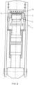
- The. 3 show in detail the structure of the press ram 2.
- the basis of the press ram 2 is a stamp foot 5.
- the stamp foot 5 is connected to a lower part 6 of the stamp.
- a heating cartridge 7 is located in the upper area of the stamp lower part 6.
- the lower part of the stamp 6 is connected to a compensating plate 8 just above the heating cartridge 7 .
- This compensating plate 8 is made of a thermally highly conductive material. Copper alloys have proven their worth, namely materials from the "low-alloy copper" range. The copper content of approx. 95% is alloyed with nickel, silicon, cobalt and beryllium, for example, which results in particularly good thermal conductivity combined with high mechanical strength.
- a pressing plate 9 is located above the compensating plate 8 so that pressing can be carried out directly. This pressing plate 9 comes into contact with the compound mixture to be pressed. Not shown in the figure is a likewise possible vertical (and not horizontal) installation of the heating cartridge. With such an installation, the heating cartridge could also protrude through the compensating plate into the press plate.
- the 4 shows a longitudinal section through the upper tool 4.
- the upper tool 4 is attached to an upper press yoke 10.
- An insulating material plate 11 is fastened to the upper press yoke 10 and serves to thermally separate the heated parts of the upper tool 4 from the remaining, unheated parts.
- a heating plate 12 is attached on the insulating material plate 11, a heating plate 12 is attached.
- the heating plate 12 is made of highly thermally conductive material. Copper alloys alloyed with nickel, silicon, cobalt and beryllium have proven themselves.
- heating cartridges 13 are pressed or glued.
- the heating plate 12 is connected to a mirror plate 14 on its underside. The mirror plate 14 comes into contact with the plastic-based compounds to be pressed or alternatively (not shown) in the case of friction linings, in some cases also with a lining carrier which is made of metal or plastic and with which the friction lining is pressed.
- the pressing tool must always have a pressing stamp and a mirror plate (as the respective counterpart).
- the press ram has a compensating plate made of highly thermally conductive materials or the mirror plate has a heating plate made of highly thermally conductive materials.
Landscapes
- Engineering & Computer Science (AREA)
- Mechanical Engineering (AREA)
- Chemical & Material Sciences (AREA)
- Composite Materials (AREA)
- Casting Or Compression Moulding Of Plastics Or The Like (AREA)
- Moulds For Moulding Plastics Or The Like (AREA)
Abstract
Die Erfindung betrifft ein Presswerkzeug (1) zum Verpressen von kunststoffgebundenen Compoundmischungen. Dieses Presswerkzeug (1) weist eine Pressform (3), einen Pressstempel (2) und ein Oberwerkzeug (4) auf. Bei bekannten Presswerkzeugen bestehen alle Teile des Pressstempels aus verschiedenen Stählen, wodurch es an der Stempeloberfläche zu größeren Temperaturunterschieden kommt. Da diese Temperaturunterschiede die Qualität des Pressgutes mindern, weist zur Erreichung einer möglichst homogenen Temperaturvertrteilung bei der gegenständlichen Erfindung der Pressstempel (2) eine Ausgleichsplatte (8) aus thermisch hochleitfähigem Material auf, wobei sich dafür beispielsweise Kupferlegierungen, und zwar Werkstoffe aus dem Bereich "niedriglegiertes Kupfer" bewährt haben.
Description
- Die Erfindung betrifft ein Presswerkzeug zum Verpressen von kunststoffgebundenen Compoundmischungen, bestehend aus einer Pressform, einem Pressstempel und einem Oberwerkzeug.
- Kunststoffgebundene Compounds werden bei der Herstellung von Graphitplatten in Brennstoffzellen bzw. bei der Herstellung von Reibbelägen verwendet.
- Stand der Technik ist, dass die Pressform mit einer definierten Menge der zu verpressenden Compoundmischung befüllt wird. Anschließend wird die Presse geschlossen. Dabei wird eine beheizte Metallplatte, welche im Folgenden als Spiegelplatte bezeichnet wird und Teil des Oberwerkzeuges ist, auf die Pressform aufgesetzt und damit die Pressform abgedichtet. Dadurch kann der erforderliche Pressdruck aufgebaut werden. Danach wird die Compoundmischung mit Hilfe des Pressstempels, oder eines Kolbens, unter Einwirkung von erhöhtem Druck und erhöhter Temperatur verpresst.
- Die verwendeten Bindemittel, meist Harze, schmelzen bei der erhöhten Temperatur des Pressvorganges und verkleben und/oder vernetzen (chemisch) die übrigen Bestandteile der Pressmischung (eben die zu verpressenden Compoundmischungen) zu einem homogenen, festen und dichten Körper.
- Üblich ist, dass der Presstempel und die Spiegelplatte dabei elektrisch beheizt werden. Eine andere Heizung, z.B. mit Thermoöl ist jedoch auch möglich und Stand der Technik.
- Bei den bekannten Presswerkzeugen bestehen alle Teile des Pressstempels aus verschiedenen Stählen. Dies hat zur Folge, dass insbesondere an der Stempeloberfläche, welche mit dem Pressgut in Berührung kommt, größere Temperaturunterschiede zwischen dem Rand und der Mitte von bis zu 40 Grad Celsius auftreten. Eine konstante Temperaturverteilung über die Stempeloberfläche ist nicht gegeben, wodurch die Produktqualität des Pressgutes leidet.
- Beim Oberwerkzeug besteht die Heizplatte, mit welcher die Spiegelplatte verbunden ist, gemäß dem Stand der Technik ebenfalls aus Stahl, wodurch die gleichen Probleme der Temperaturunterschiede und der nicht konstanten Temperaturverteilung wie bei der Stempeloberfläche entstehen. Es kommt an der Oberfläche der Spiegelplatte zu unterschiedlichen Temperaturen in Abhängigkeit vom Abstand zur Heizpatrone.
- Die Erfindung hat es sich zum Ziel gesetzt die inhomogene Temperaturverteilung innerhalb des Presswerkzeuges zu minimieren respektive zu beseitigen, wodurch die Produktqualität der kunststoffgebundenen Compounds gesteigert werden kann.
- Diese Aufgabe wird durch eine Veränderung des Werkzeuges gelöst, dadurch, dass der Pressstempel eine Ausgleichsplatte aus thermisch hochleitfähigem Material aufweist. Bewährt hat sich ein Aufbau der Ausgleichsplatte aus Kupfer oder einer hochfesten Kupferlegierung. Diese Kupferlegierungen sind Werkstoffe aus dem Bereich "niedriglegiertes Kupfer". Sie werden z.B. mit Nickel, Silicium, Kobalt und Beryllium legiert und haben in der Regel eine Kupferanteil von ca. 95 %. Sie zeichnen sich durch besonders gute Wärmeleitfähigkeit bei geleichzeitig guten mechanischen Eigenschaften aus. Eine derartige Ausgleichsplatte verbessert die Temperaturverteilung über die Oberfläche des Pressstempels deutlich.
- Vorstellbar sind aber auch andere thermisch hochleitfähige Materialien, wie z. B. Silberlegierungen.
- Zur Erreichung einer hohen Qualität des verpressten Compounds ist es zweckmäßig, wenn auch die Heizplatte des Oberwerkzeuges aus thermisch hochleitfähigen Materialien, wie z.B. aus Kupfer- oder Silberlegierungen, wie sie oben beschrieben sind, aufgebaut ist. Dadurch wird auch im Bereich der Oberfläche der Spiegelplatte eine homogene Temperaturverteilung zur Qualitätssteigerung des fertig gepressten Compounds erreicht. Die maximalen Temperaturunterschiede werden dadurch so weit als möglich verringert.
- Eine gute Ausgestaltung wird erreicht, wenn die Ausgleichsplatte des Pressstempels eine Stärke von 3 bis 50 mm aufweist.
- Vorteilhaft ist es, wenn die Heizplatte des Oberwerkzeuges eine Stärke von 15 bis 50 mm aufweist.
- Gute Erfolge beim Verpressen von Compoundmischungen sind dadurch erreichbar, dass die Heizleistungen der Heizpatronen im Bereich zwischen 100 und 20.000 Watt liegen.
- Gute Erfolge sind weiters dann zu erzielen, wenn die thermisch hochleitfähige Ausgleichsplatte des Pressstempels und/oder die Heizplatte des Oberwerkzeuges eine Wärmeleitfähigkeit im Bereich von 80 bis 500 Watt/(m K) aufweisen.
- Nachstehend wird die erfindungsgemäße Vorrichtung in den Zeichnungen anhand eines Beispiels dargestellt. Dabei zeigt:
- die
Fig. 1 ein geöffnetes Presswerkzeug, eingebaut in eine Presse, in Vorderansicht. - Die
Fig. 2 zeigt das identische in eine Presse eingebaute Presswerkzeug, welches jedoch geschlossen ist, in Vorderansicht. - Die
Fig. 3 zeigt in einem Längsschnitt den Pressstempel. - Die
Fig. 4 zeigt in einem Längsschnitt das Oberwerkzeug. - Die
Fig. 1 zeigt ein geöffnetes Presswerkzeug 1. Das Presswerkzeug 1 weist einen Pressstempel 2 auf. Weiters ist eine Pressform 3 angeordnet. Diese Pressform 3 wird beim Betrieb des Presswerkzeuges 1 bei jedem Pressvorgang mit einer definierten Menge der zu verpressenden Compoundmischung befüllt. - Im geöffneten Zustand des Presswerkzeuges 1 liegt ein Oberwerkzeuges 4 frei, das heißt dieses liegt nicht auf der Pressform 3 auf. Der untere Teil des Oberwerkzeuges 4 wird durch eine Spiegelplatte 14 gebildet.
- Die
Fig. 2 zeigt das identische Presswerkzeug 1 in geschlossenem Zustand. Der Pressstempel 2 verpresst die kunststoffgebundenen Compoundmischungen, mit welchen die Pressform 3 befüllt ist. Das beheizte Oberwerkzeug 4, dessen unterer Teil durch die Spiegelplatte 14 gebildet wird, wird auf die Pressform 3 aufgesetzt, um eine Abdichtung zu erreichen. Aufgrund der Abdichtung kann der erforderliche Pressdruck aufgebaut werden. Ohne Abdichtung würden die Compoundmischungen beim Verpressen entweichen. - Die.
Fig. 3 zeigen im Detail den Aufbau des Pressstempels 2. Basis des Pressstempels 2 ist ein Stempelfuß 5. Der Stempelfuß 5 ist mit einem Stempelunterteil 6 verbunden. Im oberen Bereich des Stempelunterteils 6 befindet sich eine Heizpatrone 7. - Um eine möglichst homogene Temperaturverteilung zu gewährleisten ist der Stempelunterteil 6 knapp oberhalb der Heizpatrone 7 mit einer Ausgleichsplatte 8 verbunden. Diese Ausgleichsplatte 8 ist aus einem thermisch hochleitfähigen Material aufgebaut. Bewährt haben sich Kupferlegierungen, und zwar Werkstoffe aus dem Bereich "niedriglegiertes Kupfer". Der Kupferanteil von ca. 95% wird zum Beispiel mit Nickel, Silicium, Kobalt und Beryllium legiert, wodurch sich bei gleichzeitig hoher mechanischer Festigkeit eine besonders gute Wärmeleitfähigkeit ergibt.
- Zur unmittelbaren Durchführung der Pressung befindet sich oberhalb der Ausgleichsplatte 8 eine Pressplatte 9. Diese Pressplatte 9 kommt mit der zu verpressenden Compoundmischung in Berührung. In der Figur nicht gezeigt ist ein ebenfalls möglicher vertikaler (und nicht horizontaler) Einbau der Heizpatrone. Bei einem derartigen Einbau könnte die Heizpatrone auch durch die Ausgleichsplatte in die Pressplatte ragen.
- Die
Fig. 4 zeigt einen Längsschnitt durch das Oberwerkzeug 4. Das Oberwerkzeug 4 ist an einem oberen Pressenjoch 10 befestigt. An dem oberen Pressenjoch 10 ist eine Isoliermaterialplatte 11 befestigt, welche dazu dient, die beheizten Teile des Oberwerkzeuges 4 thermisch von den restlichen, nicht beheizten Teilen, zu trennen. - Auf der Isoliermaterialplatte 11 ist eine Heizplatte 12 befestigt. Die Heizplatte 12 ist aus thermisch hochleitfähigem Material aufgebaut. Bewährt haben sich mit Nickel, Silicium, Kobalt und Beryllium legierte Kupferlegierungen. In die Heizplatte 12 sind Heizpatronen 13 eingepresst oder eingeklebt. Die Heizplatte 12 ist an ihrer Unterseite mit einer Spiegelplatte 14 verbunden. Die Spiegelplatte 14 kommt mit den zu verpressenden kunststoffbasierten Compounds in Kontakt oder alternativ (nicht gezeigt) bei Reibbelägen, teilweise auch mit einem Belagträger, welcher aus Metall oder Kunststoff besteht und mit welchem der Reibbelag verpresst wird, in Kontakt.
- Vorstellbar sind Abänderungen des erfindungsgemäßen Presswerkzeuges. Das Presswerkzeug muss zwar immer einen Pressstempel und eine Spiegelplatte (als jeweiliges Gegenstück) aufweisen. Zur Vereinfachung wäre es aber möglich, dass lediglich entweder der Pressstempel eine aus thermisch hochleitfähigen Materialien aufgebaute Ausgleichsplatte aufweist oder die Spiegelplatte weist eine aus thermisch hochleitfähigen Materialien aufgebaute Heizplatte auf.
Claims (6)
- Presswerkzeug (1) zum Verpressen einer Compoundmischung, bestehend aus einer Pressform (3), einem Pressstempel (2) und einem Oberwerkzeug (4), dadurch gekennzeichnet, dass der Pressstempel (2) eine Ausgleichsplatte (8) aus thermisch hochleitfähigem Material aufweist.
- Presswerkzeug (1) nach Anspruch 1, dadurch gekennzeichnet, dass die Heizplatte (12) des Oberwerkzeuges (4) aus thermisch hochleitfähigem Material aufgebaut ist.
- Presswerkzeug (1) nach Anspruch 1 oder 2, dadurch gekennzeichnet, dass die Ausgleichsplatte (8) des Pressstempels (2) eine Stärke von 3 bis 50 mm aufweist.
- Presswerkzeug (1) nach einem der Ansprüche 1 bis 3, dadurch gekennzeichnet, dass die Heizplatte (12) des Oberwerkzeuges (4) eine Stärke von 15 bis 50 mm aufweist.
- Presswerkzeug (1) nach einem der Ansprüche 1 bis 4, dadurch gekennzeichnet, dass die Heizleistungen der Heizpatronen (7) und (13) jeweils zwischen 100 und 20.000 Watt aufweisen.
- Presswerkzeug (1) nach einem der Ansprüche 1 bis 5, dadurch gekennzeichnet, dass die Ausgleichsplatte (8) des Pressstempels (2) und/oder die Heizplatte (13) des Oberwerkzeuges (4) eine Wärmeleitfähigkeit im Bereich von 80 bis 500 Watt/(m K) aufweisen.
Applications Claiming Priority (1)
| Application Number | Priority Date | Filing Date | Title |
|---|---|---|---|
| ATGM102/2021U AT17830U1 (de) | 2021-10-18 | 2021-10-18 | Presswerkzeug zum Verpressen von Compoundmischungen |
Publications (1)
| Publication Number | Publication Date |
|---|---|
| EP4166313A1 true EP4166313A1 (de) | 2023-04-19 |
Family
ID=78821157
Family Applications (1)
| Application Number | Title | Priority Date | Filing Date |
|---|---|---|---|
| EP21450002.7A Withdrawn EP4166313A1 (de) | 2021-10-18 | 2021-11-25 | Presswerkzeug zum verpressen von compoundmischungen |
Country Status (2)
| Country | Link |
|---|---|
| EP (1) | EP4166313A1 (de) |
| AT (1) | AT17830U1 (de) |
Citations (9)
| Publication number | Priority date | Publication date | Assignee | Title |
|---|---|---|---|---|
| US3615880A (en) * | 1968-04-03 | 1971-10-26 | Gen Electric | Ferrous metal die casting process and products |
| CN1033027A (zh) * | 1987-09-29 | 1989-05-24 | 约翰·莱因韦伯机械公司 | 用于生产摩擦衬垫的压制机的装料方法 |
| US7465371B2 (en) * | 2003-11-12 | 2008-12-16 | Bachmann Kunststoff Technologien Gmbh | Hot pressing apparatus with a pressure plate and at least one resilient lining |
| JP2011177767A (ja) * | 2010-03-03 | 2011-09-15 | Union Seimitsu:Kk | 圧造工具 |
| KR101184155B1 (ko) * | 2008-07-30 | 2012-09-18 | 후지쯔 가부시끼가이샤 | 가압 가열 장치 및 방법 |
| US20160297161A1 (en) * | 2013-09-24 | 2016-10-13 | Tmd Friction Services Gmbh | Device and method for the production of friction linings and brake linings |
| US9914275B1 (en) * | 2014-11-20 | 2018-03-13 | Akebono Brake Industry Co., Ltd. | Thermally-conductive hot press assembly |
| US10987831B2 (en) * | 2019-05-24 | 2021-04-27 | The Boeing Company | Dies for forming a part and associated systems and methods |
| CN113169093A (zh) * | 2018-12-20 | 2021-07-23 | 奥托马特里克斯责任有限公司 | 用于在基板上烧结电子器件的烧结压机 |
Family Cites Families (4)
| Publication number | Priority date | Publication date | Assignee | Title |
|---|---|---|---|---|
| DE2343680A1 (de) * | 1973-08-30 | 1975-04-24 | Degussa | Verfahren und vorrichtung zur herstellung von flachen formkoerpern aus pulvern oder granulaten |
| JPH01228700A (ja) * | 1988-03-10 | 1989-09-12 | Ishikawajima Harima Heavy Ind Co Ltd | プレス装置 |
| FR2658753A1 (fr) * | 1990-02-23 | 1991-08-30 | Snecma | Dispositif de moulage en materiau composite pour le pressage a chaud de pieces en materiau refractaire. |
| AT520292B1 (de) * | 2018-02-21 | 2019-03-15 | Engel Austria Gmbh | Verfahren zum Aufheizen von Halbzeugen |
-
2021
- 2021-10-18 AT ATGM102/2021U patent/AT17830U1/de not_active IP Right Cessation
- 2021-11-25 EP EP21450002.7A patent/EP4166313A1/de not_active Withdrawn
Patent Citations (10)
| Publication number | Priority date | Publication date | Assignee | Title |
|---|---|---|---|---|
| US3615880A (en) * | 1968-04-03 | 1971-10-26 | Gen Electric | Ferrous metal die casting process and products |
| CN1033027A (zh) * | 1987-09-29 | 1989-05-24 | 约翰·莱因韦伯机械公司 | 用于生产摩擦衬垫的压制机的装料方法 |
| US7465371B2 (en) * | 2003-11-12 | 2008-12-16 | Bachmann Kunststoff Technologien Gmbh | Hot pressing apparatus with a pressure plate and at least one resilient lining |
| KR101184155B1 (ko) * | 2008-07-30 | 2012-09-18 | 후지쯔 가부시끼가이샤 | 가압 가열 장치 및 방법 |
| JP2011177767A (ja) * | 2010-03-03 | 2011-09-15 | Union Seimitsu:Kk | 圧造工具 |
| US20160297161A1 (en) * | 2013-09-24 | 2016-10-13 | Tmd Friction Services Gmbh | Device and method for the production of friction linings and brake linings |
| EP2999586B1 (de) * | 2013-09-24 | 2017-12-20 | TMD Friction Services GmbH | Vorrichtung und verfahren zur herstellung von reib- und bremsbelägen |
| US9914275B1 (en) * | 2014-11-20 | 2018-03-13 | Akebono Brake Industry Co., Ltd. | Thermally-conductive hot press assembly |
| CN113169093A (zh) * | 2018-12-20 | 2021-07-23 | 奥托马特里克斯责任有限公司 | 用于在基板上烧结电子器件的烧结压机 |
| US10987831B2 (en) * | 2019-05-24 | 2021-04-27 | The Boeing Company | Dies for forming a part and associated systems and methods |
Also Published As
| Publication number | Publication date |
|---|---|
| AT17830U1 (de) | 2023-04-15 |
Similar Documents
| Publication | Publication Date | Title |
|---|---|---|
| CH687685A5 (de) | Giessmaschine und Verfahren. | |
| DE2321103C3 (de) | Verfahren zur Herstellung eines phosphorhaltigen Stahlpulvers | |
| DE102015120156A1 (de) | Vorrichtung zur materialschlüssigen Verbindung von Verbindungspartnern eines Leistungselekronik-Bauteils | |
| EP0032545A1 (de) | Verfahren und Vorrichtung zur Umwandlung von Stoffen unter Anwendung hoher Drucke und Temperaturen | |
| DE1790300A1 (de) | Verfahren zum verbinden von werkstuecken mit einer unterlage | |
| DE60218062T2 (de) | Rückenplatte sowie verfahren zu ihrer herstellung | |
| CH693767A5 (de) | Gruenlingelektrode fuer Funkenoberflaechenbehandlung und Methode zum Herstellen der Gruenlingelektrode fuer Funkenoberflaechenbehandlung. | |
| DE1223810B (de) | Hochdruckapparatur mit sich verjuengenden Pressstempeln | |
| DE1962420A1 (de) | Werkzeug zur Herstellung von Gegenstaenden oder Presslingen aus Metallpulvern oder anderen Pulvern | |
| DE1202854B (de) | Verfahren zur Herstellung einer gedruckten Schaltung | |
| DE112011104730T5 (de) | Verfahren zur Herstellung eines zusammengepressten Metallschrottblocks | |
| CH693846A5 (de) | Gronlingelektrode zur Oberflachenbehandlung durch Funkenerosion. | |
| DE3029777A1 (de) | Material fuer eine biegsame leitende verbindung insbesondere fuer flugzeuge | |
| DE102005034200A1 (de) | Kaltpressschweissverfahren und hiermit hergestelltes Produkt | |
| EP4166313A1 (de) | Presswerkzeug zum verpressen von compoundmischungen | |
| EP2809461A1 (de) | Vorrichtung und verfahren zur herstellung von porenfreien profilen aus trennresten mittels strangpressen | |
| DE102006022264B4 (de) | Siegelwerkzeug zum Siegeln von Folien in einer Siegelstation | |
| DE2455348C2 (de) | Verfahren und Vorrichtung zur Herstellung von flüssigkeitsdichten Verbindungen zwischen Plattengruppen in benachbarten Zellen einer elektrischen Blei-Säure-Speicherbatterie | |
| DE2504032C2 (de) | ||
| DE850031C (de) | Bimetallkontakte | |
| DE3419057A1 (de) | Presse zum aufbringen einer schicht auf eine traegerplatte, insbesondere eine scheibenbremsbelagtraegerplatte | |
| DE19745283A1 (de) | Verfahren zur Herstellung von Bauteilen aus Pulvern | |
| WO2015000794A1 (de) | Verfahren zum unlösbaren verbinden von bauteilen oder bauteilbereichen sowie unlösbare verbindung | |
| DE3022842A1 (de) | Reibkoerper fuer scheibenbremsen und verfahren zur herstellung dieses reibkoerpers | |
| EP1027306A1 (de) | Verfahren zur herstellung von bauteilen aus pulvern |
Legal Events
| Date | Code | Title | Description |
|---|---|---|---|
| PUAI | Public reference made under article 153(3) epc to a published international application that has entered the european phase |
Free format text: ORIGINAL CODE: 0009012 |
|
| STAA | Information on the status of an ep patent application or granted ep patent |
Free format text: STATUS: THE APPLICATION HAS BEEN PUBLISHED |
|
| AK | Designated contracting states |
Kind code of ref document: A1 Designated state(s): AL AT BE BG CH CY CZ DE DK EE ES FI FR GB GR HR HU IE IS IT LI LT LU LV MC MK MT NL NO PL PT RO RS SE SI SK SM TR |
|
| STAA | Information on the status of an ep patent application or granted ep patent |
Free format text: STATUS: THE APPLICATION IS DEEMED TO BE WITHDRAWN |
|
| 18D | Application deemed to be withdrawn |
Effective date: 20231020 |