EP4166385A1 - N ud de composant - Google Patents
N ud de composant Download PDFInfo
- Publication number
- EP4166385A1 EP4166385A1 EP21202720.5A EP21202720A EP4166385A1 EP 4166385 A1 EP4166385 A1 EP 4166385A1 EP 21202720 A EP21202720 A EP 21202720A EP 4166385 A1 EP4166385 A1 EP 4166385A1
- Authority
- EP
- European Patent Office
- Prior art keywords
- component
- control
- control unit
- control circuit
- node
- Prior art date
- Legal status (The legal status is an assumption and is not a legal conclusion. Google has not performed a legal analysis and makes no representation as to the accuracy of the status listed.)
- Pending
Links
- 239000007788 liquid Substances 0.000 claims description 11
- 239000000110 cooling liquid Substances 0.000 claims description 9
- 238000004146 energy storage Methods 0.000 claims description 4
- 230000006978 adaptation Effects 0.000 claims description 2
- 230000002457 bidirectional effect Effects 0.000 claims description 2
- 238000006243 chemical reaction Methods 0.000 claims description 2
- 238000010586 diagram Methods 0.000 description 6
- 239000002826 coolant Substances 0.000 description 3
- 239000003507 refrigerant Substances 0.000 description 3
- 238000004891 communication Methods 0.000 description 2
- 230000001276 controlling effect Effects 0.000 description 2
- 239000000446 fuel Substances 0.000 description 2
- 238000001816 cooling Methods 0.000 description 1
- 230000001419 dependent effect Effects 0.000 description 1
- 238000013461 design Methods 0.000 description 1
- 238000011161 development Methods 0.000 description 1
- 239000012530 fluid Substances 0.000 description 1
- 230000010354 integration Effects 0.000 description 1
- 238000000034 method Methods 0.000 description 1
- 230000001105 regulatory effect Effects 0.000 description 1
- 238000012546 transfer Methods 0.000 description 1
Images


Classifications
-
- B—PERFORMING OPERATIONS; TRANSPORTING
- B60—VEHICLES IN GENERAL
- B60L—PROPULSION OF ELECTRICALLY-PROPELLED VEHICLES; SUPPLYING ELECTRIC POWER FOR AUXILIARY EQUIPMENT OF ELECTRICALLY-PROPELLED VEHICLES; ELECTRODYNAMIC BRAKE SYSTEMS FOR VEHICLES IN GENERAL; MAGNETIC SUSPENSION OR LEVITATION FOR VEHICLES; MONITORING OPERATING VARIABLES OF ELECTRICALLY-PROPELLED VEHICLES; ELECTRIC SAFETY DEVICES FOR ELECTRICALLY-PROPELLED VEHICLES
- B60L3/00—Electric devices on electrically-propelled vehicles for safety purposes; Monitoring operating variables, e.g. speed, deceleration or energy consumption
- B60L3/12—Recording operating variables ; Monitoring of operating variables
-
- B—PERFORMING OPERATIONS; TRANSPORTING
- B60—VEHICLES IN GENERAL
- B60L—PROPULSION OF ELECTRICALLY-PROPELLED VEHICLES; SUPPLYING ELECTRIC POWER FOR AUXILIARY EQUIPMENT OF ELECTRICALLY-PROPELLED VEHICLES; ELECTRODYNAMIC BRAKE SYSTEMS FOR VEHICLES IN GENERAL; MAGNETIC SUSPENSION OR LEVITATION FOR VEHICLES; MONITORING OPERATING VARIABLES OF ELECTRICALLY-PROPELLED VEHICLES; ELECTRIC SAFETY DEVICES FOR ELECTRICALLY-PROPELLED VEHICLES
- B60L1/00—Supplying electric power to auxiliary equipment of vehicles
- B60L1/003—Supplying electric power to auxiliary equipment of vehicles to auxiliary motors, e.g. for pumps, compressors
-
- B—PERFORMING OPERATIONS; TRANSPORTING
- B60—VEHICLES IN GENERAL
- B60L—PROPULSION OF ELECTRICALLY-PROPELLED VEHICLES; SUPPLYING ELECTRIC POWER FOR AUXILIARY EQUIPMENT OF ELECTRICALLY-PROPELLED VEHICLES; ELECTRODYNAMIC BRAKE SYSTEMS FOR VEHICLES IN GENERAL; MAGNETIC SUSPENSION OR LEVITATION FOR VEHICLES; MONITORING OPERATING VARIABLES OF ELECTRICALLY-PROPELLED VEHICLES; ELECTRIC SAFETY DEVICES FOR ELECTRICALLY-PROPELLED VEHICLES
- B60L1/00—Supplying electric power to auxiliary equipment of vehicles
- B60L1/02—Supplying electric power to auxiliary equipment of vehicles to electric heating circuits
- B60L1/04—Supplying electric power to auxiliary equipment of vehicles to electric heating circuits fed by the power supply line
- B60L1/06—Supplying electric power to auxiliary equipment of vehicles to electric heating circuits fed by the power supply line using only one supply
- B60L1/08—Methods and devices for control or regulation
-
- B—PERFORMING OPERATIONS; TRANSPORTING
- B60—VEHICLES IN GENERAL
- B60L—PROPULSION OF ELECTRICALLY-PROPELLED VEHICLES; SUPPLYING ELECTRIC POWER FOR AUXILIARY EQUIPMENT OF ELECTRICALLY-PROPELLED VEHICLES; ELECTRODYNAMIC BRAKE SYSTEMS FOR VEHICLES IN GENERAL; MAGNETIC SUSPENSION OR LEVITATION FOR VEHICLES; MONITORING OPERATING VARIABLES OF ELECTRICALLY-PROPELLED VEHICLES; ELECTRIC SAFETY DEVICES FOR ELECTRICALLY-PROPELLED VEHICLES
- B60L58/00—Methods or circuit arrangements for monitoring or controlling batteries or fuel cells, specially adapted for electric vehicles
- B60L58/10—Methods or circuit arrangements for monitoring or controlling batteries or fuel cells, specially adapted for electric vehicles for monitoring or controlling batteries
- B60L58/24—Methods or circuit arrangements for monitoring or controlling batteries or fuel cells, specially adapted for electric vehicles for monitoring or controlling batteries for controlling the temperature of batteries
- B60L58/26—Methods or circuit arrangements for monitoring or controlling batteries or fuel cells, specially adapted for electric vehicles for monitoring or controlling batteries for controlling the temperature of batteries by cooling
-
- B—PERFORMING OPERATIONS; TRANSPORTING
- B60—VEHICLES IN GENERAL
- B60L—PROPULSION OF ELECTRICALLY-PROPELLED VEHICLES; SUPPLYING ELECTRIC POWER FOR AUXILIARY EQUIPMENT OF ELECTRICALLY-PROPELLED VEHICLES; ELECTRODYNAMIC BRAKE SYSTEMS FOR VEHICLES IN GENERAL; MAGNETIC SUSPENSION OR LEVITATION FOR VEHICLES; MONITORING OPERATING VARIABLES OF ELECTRICALLY-PROPELLED VEHICLES; ELECTRIC SAFETY DEVICES FOR ELECTRICALLY-PROPELLED VEHICLES
- B60L2240/00—Control parameters of input or output; Target parameters
- B60L2240/40—Drive Train control parameters
- B60L2240/54—Drive Train control parameters related to batteries
- B60L2240/545—Temperature
Definitions
- the invention relates to a component node for a vehicle with an electric drive motor and an electric energy storage device according to the generic concept of claim 1.
- a vehicle with an electric drive motor and an electric energy storage system can be a purely battery electric vehicle or a fuel cell vehicle or a hybrid vehicle.
- a liquid guiding circuit of the vehicle can contain several functional components through which cooling liquid such as coolant and/or refrigerant can flow. The challenge is to arrange the individual components in the vehicle in a space-saving manner.
- the complex mechatronic functional components usually contain control units and/or communication interfaces for communicating with the on-board electronics of the vehicle.
- the analog functional components on the other hand, often contain no interfaces and their signals also contain to be pre-processed. Interconnecting of the functional components with the on-board electronics therefore involves a great deal of effort.
- the present invention is based on the general idea of centrally controlling or regulating functional components of a component node and arranging a corresponding control unit at the component node.
- Component node is provided for a vehicle with an electric drive motor and an electric energy storage device.
- the vehicle can be a purely battery electric vehicle or a fuel cell vehicle or a hybrid vehicle.
- the component node contains at least one functional component through which cooling liquid can flow for at least one liquid guiding circuit of the vehicle and a component carrier.
- the at least one liquid guiding circuit can be a refrigerant circuit and/or a coolant circuit.
- a component interface is formed on the component carrier for the respective functional component, and the respective functional component is detachably attached to the component carrier via the component interface.
- the component node contains a control circuit with at least one control unit and at least one control component. The control component is thereby connected into the control circuit and is provided for the one functional component.
- the control component connected in the circuit can be controlled by the control unit, thereby eliminating the need to connect the control component to an on-board electronics of the vehicle.
- the number of interfaces in the component node can be significantly reduced.
- the compact arrangement of the functional components and the control unit on the component node can achieve a high level of component integration, thereby providing a cost-optimized solution.
- the component node can ensure a demand-oriented distribution of cooling liquid in the at least one liquid guiding circuit.
- the control circuit in the component node also enables temperature management of the at least one liquid guiding circuit.
- the at least one functional component can realize an essential or indispensable fluidic function in the at least one liquid guiding circuit, such as cooling or collecting or condensing the cooling liquid.
- the component carrier may be designed exclusively to support the at least one functional component.
- the component carrier may be designed exclusively for supporting the at least one functional component and for connecting the at least one functional component to the at least one liquid guiding circuit of the vehicle via a fluid line formed in the component carrier.
- the component node can contain several - but at least two - functional components and several - but at least two - control components connected to the control circuit.
- the individual functional components can be fluidically integrated into different liquid guiding circuits - for example into a refrigerant circuit and a coolant circuit.
- the at least two control components connected into the control circuit may be controllable interdependently of each other via the control unit.
- the at least two control components connected to the control circuit can be automatically addressable via a BUS system.
- the at least one control component can be assigned to the at least one functional component and the at least one functional component can be controlled via the at least one control component.
- the at least one functional component can be represented by a mechatronic component and the at least one control component can be represented by power electronics.
- the mechatronic component may be an expansion valve or a pump or a motor or a compressor.
- the control component may then be provided for controlling the expansion valve or the pump or the motor or the compressor.
- the at least one control component can be assigned to the at least one functional component and be designed for measuring of data on the at least one functional component.
- the at least one control component can be represented by a sensor.
- the sensor can be a temperature sensor for detecting temperature at the at least one functional component or a filling level sensor for detecting filling level of the at least one functional component or a pressure sensor for detecting pressure in the at least one functional component.
- the control unit can be designed for AD conversion and signal adaptation of sensor signals received by the at least one sensor.
- the respective functional component may be assigned a single control component and/or the respective functional component may be assigned more than one control component and/or the several functional components may be assigned a common control component.
- the component node it may be provided that all control components of the component node are connected into the control circuit of the component node. If the component node contains several - but at least two - control components, all control components are connected into the control circuit and the control unit can regulate or control all functional components associated with the control components. In this embodiment, the functional components of the component node can be connected to the outside in a signal-transmitting and power-transmitting manner via a single connector of the control unit.
- the component node contains at least one further control component for the at least one functional component that is not connected into the control circuit.
- the control component of the at least one functional component may not be controlled by the control unit.
- the control component that is not connected to the control circuit can itself be connected to the outside in a signal-transmitting and power-transmitting manner and be controlled externally - for example via the on-board electronics of the vehicle.
- the component node contains at least one further control component, not connected into the control circuit, for the at least one functional component.
- the control unit and the at least one further control component can be connected to the outside via a common connector in a signal-transmitting and/or power-transmitting manner.
- the control components of the component node can also be connected to the outside via a single connector in a signal-transmitting and power-transmitting manner.
- the component node contains at least one component for the at least one liquid guiding circuit, wherein the at least one component is not attached to the component carrier of the component node.
- the component node then contains at least one further control component connected into the control circuit for the at least one component.
- the component may be a fan, for example.
- the control unit can also perform control/regulation of components that are not attached to the component carrier.
- control unit and the at least one control component connected into the control circuit are connected to each other in a power-transmitting and/or signal-transmitting manner.
- the power-transmitting connection is primarily concerned with supplying the control components with current/voltage.
- the signal-transmitting connection is primarily concerned with transmitting signals between the control unit and the control component.
- the control unit and the at least one control component connected into the control circuit can be connected to each other in a signal-transmitting manner via a cable.
- the cable can preferably be a LIN cable or a CAN cable.
- the control unit and the at least one control component connected into the control circuit can be connected to each other in a signal-transmitting manner wirelessly, preferably via a Bluetooth connection or a WLAN connection.
- the control unit can be connected bidirectional via a cable, preferably via a LIN cable or a CAN cable, or wirelessly, preferably via a Bluetooth connection or a WLAN connection, in a signal-transmitting manner.
- the control unit can be detachably attached to the component carrier. It is conceivable, for example, that the control unit is clipped to the component node. In this way, the control unit can be detached from the component carrier in a simplified manner and can be replaced if necessary.
- the control unit can be detachably attached to the component carrier in such a way that the heat generated in the control unit can be transferred to the cooling liquid.
- the control unit can be arranged to transfer heat to a wall that delimits the cooling liquid from the outside.
- the wall can be assigned to the component carrier itself or to the at least one functional component.
- the control unit may contain a housing, and at least some elements of the at least one control component connected into the control circuit may be accommodated in the housing of the control unit. As a result, the component node may be more compact.
- the control unit may be arranged in a housing of the at least one functional component. The housing of the functional component then forms the housing of the control unit, in which at least some elements of the at least one control component connected into the control circuit may be arranged i.e. accommodated.
- the functional components of the simplest design can be used in the component node.
- simple analog sensors and digital sensors, single-phase or multi-phase pumps and fans, actuators for multi-way valves or compressors without integrated power electronics can be used.
- this eliminates the need for conventionally required LIN or CAN cables and integrated connectors, and the cost of the component node can be significantly reduced.
- the lack of power electronics in the component node reduces heat generated in the control circuit. As a result, the control circuit can be cooled more effectively and the service life of the control components can be extended.
- the weight and size of the component node can be significantly reduced.
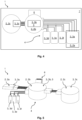
- Fig. 1 shows an interconnection diagram of a component node 1 according to the invention in a first embodiment.
- the component node 1 contains a plurality of functional components 2 and a plurality of control components 3.
- the functional components 2 are here represented by a valve actuator 2a and by two pumps 2b and 2c.
- the functional components 2 are detachably attached to a component carrier 7.
- the control components 3 are here represented by a power electronics 3a of the valve actuator 2a, a power electronics 3b and 3c of the pumps 2b and 2c, a level sensor 3d and two temperature sensors 3e and 3f.
- the component node 1 also contains a control circuit 4 with a control unit 5.
- Fig. 2 shows the control circuit 4 which control components 3 connected to the control circuit 4. Here and further, elements that are not visible from the outside are shown with broken arrows.
- the power electronics 3a of the valve actuator 2a and the power electronics 3b and 3c of the pumps 2b and 2c are not connected into the control circuit 4 and cannot be controlled by the control unit 5.
- the power electronics 3a, 3b, 3c can each be connected to the on-board electronics via their own BUS system in a signal-transmitting and power-transmitting manner.
- the sensors 3d, 3e, 3f are connected into the control circuit 4.
- the sensors 3d, 3e, 3f are connected to the control unit 5 each via a BUS system in a signal-transmitting and power-transmitting manner.
- the control unit 5 can read in, process and provide the sensor signals of the sensors 3d, 3e, 3f.
- the control unit 5 is connected to the on-board electronics via a BUS system.
- the respective BUS system can be a LIN BUS system or a CAN BUS system.
- the control unit 5 can be connected to the on-board electronics together with the power electronics 3a of the valve actuator 2a via a multi-pin connector 6.
- the BUS system of the sensor unit 5 and the BUS system of the valve actuator 2a are connected to the connector 6.
- the control unit 5 handles the communication of the sensors 3d, 3e, 3f with the on-board electronics.
- the wiring between the control components 3 is designed in such a way that auto-addressing of the control components 3 is possible.
- a total of three customer connectors are required in the first embodiment of the component node 1: two customer connectors for the power electronics 3b and 3c of the two pumps 2b and 2c and one customer connector for the connector 6.
- Fig. 3 shows an interconnection diagram of the component node 1 according to the invention in a second embodiment.
- all control components - I.e. the power electronics 3a, 3b, 3c and the sensors 3d, 3e, 3f - are connected into the control circuit 4 and can be controlled by the control unit 5.
- the control unit 5 is connected to the respective control component 3 via a BUS system in each case in a signal-transmitting and power-transmitting manner.
- the control unit 5 is also connected to the on-board electronics unit via the BUS system by means of the connector 6 in a signal-transmitting and data-transmitting manner.
- On the part of the on-board electronics only one customer connector is required for the connector 6 in the second embodiment of the component node 1.
- Fig. 4 shows an interconnection diagram of the component node 1 according to the invention in a third embodiment.
- Fig. 5 shows the control circuit 4 of the component node 1.
- the third embodiment of the component node 1 differs from the second embodiment in Fig. 3 in that the control unit 5 is arranged in a housing of the pump 2b. This allows the control circuit 4 to be designed in a particularly space-saving manner.
Landscapes
- Engineering & Computer Science (AREA)
- Power Engineering (AREA)
- Transportation (AREA)
- Mechanical Engineering (AREA)
- Life Sciences & Earth Sciences (AREA)
- Sustainable Development (AREA)
- Sustainable Energy (AREA)
- Cooling Or The Like Of Electrical Apparatus (AREA)
Priority Applications (1)
| Application Number | Priority Date | Filing Date | Title |
|---|---|---|---|
| EP21202720.5A EP4166385A1 (fr) | 2021-10-14 | 2021-10-14 | N ud de composant |
Applications Claiming Priority (1)
| Application Number | Priority Date | Filing Date | Title |
|---|---|---|---|
| EP21202720.5A EP4166385A1 (fr) | 2021-10-14 | 2021-10-14 | N ud de composant |
Publications (1)
| Publication Number | Publication Date |
|---|---|
| EP4166385A1 true EP4166385A1 (fr) | 2023-04-19 |
Family
ID=78211989
Family Applications (1)
| Application Number | Title | Priority Date | Filing Date |
|---|---|---|---|
| EP21202720.5A Pending EP4166385A1 (fr) | 2021-10-14 | 2021-10-14 | N ud de composant |
Country Status (1)
| Country | Link |
|---|---|
| EP (1) | EP4166385A1 (fr) |
Citations (4)
| Publication number | Priority date | Publication date | Assignee | Title |
|---|---|---|---|---|
| US20080251235A1 (en) * | 2007-04-11 | 2008-10-16 | Telsa Motors, Inc. | Electric vehicle thermal management system |
| DE102016111777A1 (de) * | 2015-07-10 | 2017-01-12 | Ford Global Technologies, Llc | Vorkonditionierung eines Elektrofahrzeugs |
| US20190351732A1 (en) * | 2018-05-18 | 2019-11-21 | Nio Usa, Inc. | Thermal system topology of cascaded refrigerant and coolant circuits |
| US10665908B2 (en) | 2016-06-23 | 2020-05-26 | Tesla, Inc. | Heating and cooling reservoir for a battery powered vehicle |
-
2021
- 2021-10-14 EP EP21202720.5A patent/EP4166385A1/fr active Pending
Patent Citations (4)
| Publication number | Priority date | Publication date | Assignee | Title |
|---|---|---|---|---|
| US20080251235A1 (en) * | 2007-04-11 | 2008-10-16 | Telsa Motors, Inc. | Electric vehicle thermal management system |
| DE102016111777A1 (de) * | 2015-07-10 | 2017-01-12 | Ford Global Technologies, Llc | Vorkonditionierung eines Elektrofahrzeugs |
| US10665908B2 (en) | 2016-06-23 | 2020-05-26 | Tesla, Inc. | Heating and cooling reservoir for a battery powered vehicle |
| US20190351732A1 (en) * | 2018-05-18 | 2019-11-21 | Nio Usa, Inc. | Thermal system topology of cascaded refrigerant and coolant circuits |
Similar Documents
| Publication | Publication Date | Title |
|---|---|---|
| US8067911B2 (en) | Interface cord and system including an interface cord | |
| US8162291B2 (en) | Winch | |
| US6919707B2 (en) | Battery power source device, method for controlling the same, and method for providing address | |
| US9366182B2 (en) | Integrated electrical power and thermal management system | |
| EP1511151B1 (fr) | Commande à inter-régulateur de plusieurs sources de puissance électrique | |
| US9562534B2 (en) | In-line dual pump and motor with control device | |
| CN103069697B (zh) | 热管理模块以及带有这种热管理模块的冷却系统 | |
| US8569995B2 (en) | Control circuit and method for controlling a plurality of battery cells based on a determined number of coupled battery cells | |
| US8342279B1 (en) | Modular vehicle and associated method of construction | |
| EP2884615B1 (fr) | Système modulaire de distribution d'électronique de puissance | |
| EP2357545A1 (fr) | Système de refroidissement pour tester la durée de vie d'un organe de commande de véhicule à énergie hybride | |
| US20010054395A1 (en) | Controller for pump and valve | |
| EP3088707B1 (fr) | Architecture électrique distribuée d'une turbine a gaz et procédé d'operation | |
| US20210143493A1 (en) | Temperature regulating device and device arrangement in a temperature regulating system | |
| CN111224182A (zh) | 电池模块 | |
| US20120009066A1 (en) | Drive device for a wind turbine | |
| CN109923311A (zh) | 用于商用车的压缩机系统 | |
| US12139082B2 (en) | Fluid management module and modular system | |
| EP1403119B1 (fr) | Ensemble interface pour réservoir de carburant | |
| US8534238B2 (en) | Smart fan clutch | |
| EP1596263B1 (fr) | Support intégré avec une système de commande à plusieurs moteurs | |
| US20240253451A1 (en) | Coolant tank, coolant conducting system, and motor vehicle | |
| US20230187676A1 (en) | Redox-flow battery and operating method | |
| JP2011522736A (ja) | 車両特に商用車両の補助装置を操作する装置 | |
| CN120327181A (zh) | 用于控制阀单元与泵送单元中至少一者及热泵的至少一个热泵单元的控制装置以及系统 |
Legal Events
| Date | Code | Title | Description |
|---|---|---|---|
| PUAI | Public reference made under article 153(3) epc to a published international application that has entered the european phase |
Free format text: ORIGINAL CODE: 0009012 |
|
| STAA | Information on the status of an ep patent application or granted ep patent |
Free format text: STATUS: THE APPLICATION HAS BEEN PUBLISHED |
|
| AK | Designated contracting states |
Kind code of ref document: A1 Designated state(s): AL AT BE BG CH CY CZ DE DK EE ES FI FR GB GR HR HU IE IS IT LI LT LU LV MC MK MT NL NO PL PT RO RS SE SI SK SM TR |
|
| STAA | Information on the status of an ep patent application or granted ep patent |
Free format text: STATUS: REQUEST FOR EXAMINATION WAS MADE |
|
| 17P | Request for examination filed |
Effective date: 20230725 |
|
| RBV | Designated contracting states (corrected) |
Designated state(s): AL AT BE BG CH CY CZ DE DK EE ES FI FR GB GR HR HU IE IS IT LI LT LU LV MC MK MT NL NO PL PT RO RS SE SI SK SM TR |