EP4166392B1 - Abdeckeinheit und beleuchtungsbefestigung für ein fahrzeug - Google Patents
Abdeckeinheit und beleuchtungsbefestigung für ein fahrzeug Download PDFInfo
- Publication number
- EP4166392B1 EP4166392B1 EP21202331.1A EP21202331A EP4166392B1 EP 4166392 B1 EP4166392 B1 EP 4166392B1 EP 21202331 A EP21202331 A EP 21202331A EP 4166392 B1 EP4166392 B1 EP 4166392B1
- Authority
- EP
- European Patent Office
- Prior art keywords
- driving mechanism
- opening
- cover
- cover element
- axial end
- Prior art date
- Legal status (The legal status is an assumption and is not a legal conclusion. Google has not performed a legal analysis and makes no representation as to the accuracy of the status listed.)
- Active
Links
Images



Classifications
-
- F—MECHANICAL ENGINEERING; LIGHTING; HEATING; WEAPONS; BLASTING
- F21—LIGHTING
- F21S—NON-PORTABLE LIGHTING DEVICES; SYSTEMS THEREOF; VEHICLE LIGHTING DEVICES SPECIALLY ADAPTED FOR VEHICLE EXTERIORS
- F21S41/00—Illuminating devices specially adapted for vehicle exteriors, e.g. headlamps
- F21S41/40—Illuminating devices specially adapted for vehicle exteriors, e.g. headlamps characterised by screens, non-reflecting members, light-shielding members or fixed shades
- F21S41/43—Illuminating devices specially adapted for vehicle exteriors, e.g. headlamps characterised by screens, non-reflecting members, light-shielding members or fixed shades characterised by the shape thereof
-
- B—PERFORMING OPERATIONS; TRANSPORTING
- B60—VEHICLES IN GENERAL
- B60Q—ARRANGEMENT OF SIGNALLING OR LIGHTING DEVICES, THE MOUNTING OR SUPPORTING THEREOF OR CIRCUITS THEREFOR, FOR VEHICLES IN GENERAL
- B60Q1/00—Arrangement of optical signalling or lighting devices, the mounting or supporting thereof or circuits therefor
- B60Q1/26—Arrangement of optical signalling or lighting devices, the mounting or supporting thereof or circuits therefor the devices being primarily intended to indicate the vehicle, or parts thereof, or to give signals, to other traffic
- B60Q1/2692—Arrangement of optical signalling or lighting devices, the mounting or supporting thereof or circuits therefor the devices being primarily intended to indicate the vehicle, or parts thereof, or to give signals, to other traffic retractable lights
-
- B—PERFORMING OPERATIONS; TRANSPORTING
- B60—VEHICLES IN GENERAL
- B60Q—ARRANGEMENT OF SIGNALLING OR LIGHTING DEVICES, THE MOUNTING OR SUPPORTING THEREOF OR CIRCUITS THEREFOR, FOR VEHICLES IN GENERAL
- B60Q1/00—Arrangement of optical signalling or lighting devices, the mounting or supporting thereof or circuits therefor
- B60Q1/02—Arrangement of optical signalling or lighting devices, the mounting or supporting thereof or circuits therefor the devices being primarily intended to illuminate the way ahead or to illuminate other areas of way or environments
- B60Q1/04—Arrangement of optical signalling or lighting devices, the mounting or supporting thereof or circuits therefor the devices being primarily intended to illuminate the way ahead or to illuminate other areas of way or environments the devices being headlights
- B60Q1/05—Arrangement of optical signalling or lighting devices, the mounting or supporting thereof or circuits therefor the devices being primarily intended to illuminate the way ahead or to illuminate other areas of way or environments the devices being headlights retractable
-
- F—MECHANICAL ENGINEERING; LIGHTING; HEATING; WEAPONS; BLASTING
- F16—ENGINEERING ELEMENTS AND UNITS; GENERAL MEASURES FOR PRODUCING AND MAINTAINING EFFECTIVE FUNCTIONING OF MACHINES OR INSTALLATIONS; THERMAL INSULATION IN GENERAL
- F16C—SHAFTS; FLEXIBLE SHAFTS; ELEMENTS OR CRANKSHAFT MECHANISMS; ROTARY BODIES OTHER THAN GEARING ELEMENTS; BEARINGS
- F16C11/00—Pivots; Pivotal connections
- F16C11/04—Pivotal connections
- F16C11/045—Pivotal connections with at least a pair of arms pivoting relatively to at least one other arm, all arms being mounted on one pin
-
- F—MECHANICAL ENGINEERING; LIGHTING; HEATING; WEAPONS; BLASTING
- F16—ENGINEERING ELEMENTS AND UNITS; GENERAL MEASURES FOR PRODUCING AND MAINTAINING EFFECTIVE FUNCTIONING OF MACHINES OR INSTALLATIONS; THERMAL INSULATION IN GENERAL
- F16C—SHAFTS; FLEXIBLE SHAFTS; ELEMENTS OR CRANKSHAFT MECHANISMS; ROTARY BODIES OTHER THAN GEARING ELEMENTS; BEARINGS
- F16C31/00—Bearings for parts which both rotate and move linearly
- F16C31/02—Sliding-contact bearings
-
- F—MECHANICAL ENGINEERING; LIGHTING; HEATING; WEAPONS; BLASTING
- F21—LIGHTING
- F21S—NON-PORTABLE LIGHTING DEVICES; SYSTEMS THEREOF; VEHICLE LIGHTING DEVICES SPECIALLY ADAPTED FOR VEHICLE EXTERIORS
- F21S41/00—Illuminating devices specially adapted for vehicle exteriors, e.g. headlamps
- F21S41/40—Illuminating devices specially adapted for vehicle exteriors, e.g. headlamps characterised by screens, non-reflecting members, light-shielding members or fixed shades
- F21S41/47—Attachment thereof
-
- B—PERFORMING OPERATIONS; TRANSPORTING
- B60—VEHICLES IN GENERAL
- B60Q—ARRANGEMENT OF SIGNALLING OR LIGHTING DEVICES, THE MOUNTING OR SUPPORTING THEREOF OR CIRCUITS THEREFOR, FOR VEHICLES IN GENERAL
- B60Q1/00—Arrangement of optical signalling or lighting devices, the mounting or supporting thereof or circuits therefor
- B60Q1/0005—Devices preventing the lights from becoming dirty or damaged, e.g. protection grids or cleaning by air flow
-
- F—MECHANICAL ENGINEERING; LIGHTING; HEATING; WEAPONS; BLASTING
- F16—ENGINEERING ELEMENTS AND UNITS; GENERAL MEASURES FOR PRODUCING AND MAINTAINING EFFECTIVE FUNCTIONING OF MACHINES OR INSTALLATIONS; THERMAL INSULATION IN GENERAL
- F16C—SHAFTS; FLEXIBLE SHAFTS; ELEMENTS OR CRANKSHAFT MECHANISMS; ROTARY BODIES OTHER THAN GEARING ELEMENTS; BEARINGS
- F16C11/00—Pivots; Pivotal connections
- F16C11/02—Trunnions; Crank-pins
-
- F—MECHANICAL ENGINEERING; LIGHTING; HEATING; WEAPONS; BLASTING
- F16—ENGINEERING ELEMENTS AND UNITS; GENERAL MEASURES FOR PRODUCING AND MAINTAINING EFFECTIVE FUNCTIONING OF MACHINES OR INSTALLATIONS; THERMAL INSULATION IN GENERAL
- F16C—SHAFTS; FLEXIBLE SHAFTS; ELEMENTS OR CRANKSHAFT MECHANISMS; ROTARY BODIES OTHER THAN GEARING ELEMENTS; BEARINGS
- F16C2326/00—Articles relating to transporting
- F16C2326/01—Parts of vehicles in general
Definitions
- the present invention relates to a cover unit for selectively covering or exposing lights of a vehicle, and a lighting mounting for a vehicle.
- Shutters or cover units for covering lights of a vehicle are well known.
- the cover units are configured to cover or reveal the light by performing a pivoting motion.
- cover units e.g. cover units comprising one cover element or cover units comprising two cover elements.
- the one cover element usually performs an opening movement similar to an opening garage door.
- the two cover elements are arranged parallel to each other in a closed position and during the opening and/or closing movement. Usually, the two cover elements contact each other substantially halfway, and are moving away from each other during the opening movement, and towards each other during the closing movement.
- An example retractable head-light device for automobiles is disclosed in the prior art document US 4 516 191 A .
- a cover unit for selectively covering or exposing lights of a vehicle.
- the cover unit comprises at least a first cover element for covering or exposing the opening at least partly, wherein the first cover element has a first axial end being coupled to a first driving mechanism, and a second axial end being coupled to a second driving mechanism.
- the first driving mechanism and the second driving mechanism are configured to move the first cover element between a closed position and an opened position.
- Each of the first driving mechanism and the second driving mechanism is controlled individually, and comprises an arm being configured to be rotatively coupled to the structure, at least one drive unit being configured to drive a movement of the arm, and a joint being configured to couple the arm to the respective axial end of the first cover element, and being configured to allow a two-axis rotation and one linear axis movement. Further, the joint is configured to allow the first axial end and the second axial end of the first cover element being moved differently during an opening movement for exposing the opening and/or a closing movement for covering the opening.
- Allowing the first axial end and the second axial end of the first cover element to be moved differently means that the first axial end and the second axial end may be moved different distances. This may allow more freedom to move and/or an increased range of motion. Thereby, a plurality of shapes can be covered or exposed by the cover unit, such as a rectangular shape, but also such as a triangular shape, a tapered shape and/or a trapezoidal shape. This may provide the adaptability to match various different shapes of openings, particularly modern design openings.
- the joint of each of the first driving mechanism and the second driving mechanism may allow compensating for a length difference between the first axial end and the second axial end, when they are moved different distances.
- each of the first driving mechanism and the second driving mechanism may allow a linear movement as well as a rotating movement of the respective axial end, and thus, of the first cover element, during the opening and/or closing movement. This allows achieving a reduced required space for the opening and/or closing movement of the first cover element.
- the cover unit allows adapting to a contour of the opening, which results in a reduced required installation space. Further, the cover unit allows following an exterior contour of the opening in a closed as well as in an open position.
- the cover unit may additionally comprise a second cover element, which has a first axial end being coupled to a third driving mechanism, and a second axial end being coupled to a fourth driving mechanism.
- the third driving mechanism and the fourth driving mechanism may be configured to move the second cover element between a closed position and an opened position.
- Each of the third driving mechanism and the fourth driving mechanism may be controlled individually, and may comprise an arm being configured to be rotatively coupled to the structure, at least one drive unit being configured to drive a movement of the arm, and a joint being configured to couple the arm to the respective axial end of the first cover element, and being configured to allow a two-axis rotation and one linear axis movement.
- the joint may be configured to allow the first axial end and the second axial end of the first cover element being moved differently during an opening movement for exposing the opening and/or a closing movement for covering the opening.
- the first cover element and the second cover element may be configured to contact each other in the closed position along a contact line to cover the opening, and/or the first cover element and the second cover element may be configured to be spaced apart from each other in the opened position to expose the opening.
- a second cover element may allow covering or exposing larger openings without requiring an increased space for the opening and/or closing movement. Further, the combination of the first cover element and the second cover element may increase the amount of coverable shapes the opening may have. In particular, the cover unit may increase the degree of its adaptability to a contour of the opening, which results in a reduced required installation space.
- the first axial end of the first cover element may be moved a shorter distance by the first driving mechanism that the second axial end of the first cover element by the second driving mechanism.
- the first cover element may perform an angled movement.
- the angled movement may enable the first cover element to follow an exterior design of the vehicle and/or to follow an inside cavity of the available installation space.
- controlling the first driving mechanism independent from the second driving mechanism may allow using the available installation space by providing the adaptability of the first cover element's movement.
- the first axial end of the second cover element is moved a short distance by the third driving mechanism than the second axial end of the second cover element by the fourth driving mechanism.
- the second cover element may perform an angled movement.
- the angled movement may enable the second cover element to follow an exterior design of the vehicle and/or to follow an inside cavity of the available installation space.
- controlling the third driving mechanism independent from the fourth driving mechanism may allow using the available installation space by providing the adaptability of the first cover element's movement.
- each of the first driving mechanism and the second driving mechanism may allow a retraction movement in addition to the angled movement during the opening movement, thereby further reducing the required installation space for the cover unit.
- each of the third driving mechanism and the fourth driving mechanism may be configured to move the second cover element in at least two different spatial directions, namely an opening direction and a retracting direction.
- each of the third driving mechanism and the fourth driving mechanism may allow a retraction movement in addition to the angled movement during the opening movement, thereby further reducing the required installation space for the cover unit.
- the cover unit of the first aspect is used for covering and/or exposing an opening for a lighting of a vehicle.
- cover unit for covering and/or exposing a lighting of a vehicle may provide an increased adaptability to match, particularly modern designed, lighting of a vehicle.
- the cover unit may allow adapting to a contour of a lighting, such as a headlight, a taillight etc., which results in a reduced required installation space.
- the cover unit may allow following an exterior contour of the vehicle in a closed as well as in an open position.
- a lighting mounting for a vehicle comprises a mounting body having an opening, a lighting unit comprising at least one light source, which is configured to be exposable in the opening of a body, and a cover unit of the first aspect, which is configured to close or open the opening for covering or revealing the at least one light source.
- cover unit for covering and/or exposing a lighting of a vehicle may provide an increased adaptability to match, particularly modern designed, lighting of a vehicle.
- the cover unit may allow adapting to a contour of a lighting, such as a headlight, a taillight etc., which results in a reduced required installation space.
- the cover unit may allow following an exterior contour of the vehicle in a closed as well as in an open position.
- the opening may have a substantially non-rectangular shape.
- the opening may have a tapering contour, wherein a base of the tapering contour may correspond to an outer, substantially vertical, edge of the opening when seen in the axial direction.
- the opening may have various other contours, such as a triangular contour etc.
- a non-rectangular but edgy contour may provide an appealing and modern design.
- the lighting mounting may comprise a driving unit configured to move the lighting unit towards the opening and/or to retract the lighting unit from the opening.
- Such a lighting unit may unite several different light-types needed in the vehicle, e.g. headlights for daytime running light, dimmed light, high beam light etc.
- the several light sources may be configured to spread out fan-like during while moving towards the opening.
- the light sources in the retracted position, may be arranged close to each other, thereby reducing the required installation space for storing the light sources.
- the light sources In the extracted position, the light sources may be spread out in a, particularly horizontal, axial direction, for filling out the opening provided in the body of the vehicle.
- an axial installation space for accommodating the light sources in the retracted position may be smaller than a length of the opening in the axial direction.
- the first axial end 104 is coupled to a first driving mechanism 108 and the second axial end 106 is coupled to a second driving mechanism 110.
- the first driving mechanism 108 and the second driving mechanism 110 are configured to move the first cover element 102 between a first position ( Fig. 1A ) and a second position ( Fig. 1B ). Further, the first driving mechanism 108 can be controlled and/or driven separately and independently from the second driving mechanism 110. Thus, the first axial end 104 can be moved separately from the second axial end 106.
- the two support arms 118 are arranged substantially parallel to each other and each of which comprises one connection point 114 at one longitudinal end, and is rotatively connected to the guiding arm 120 at the opposite longitudinal end. Further, the support arms 118 may be connected to a drive unit (not illustrated) configured to drive a movement of the arm 112.
- the support arms 118 can be connected to the same drive, or can be each connected to a separate drive unit.
- the drive unit may be, for example, an electric motor.
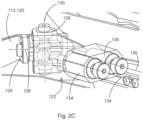
- the guiding arm 120 is connected to the first cover element 102 by a joint 122.
- the joint 122 is able to perform a two-axis rotation and one linear axis movement and will be explained in detail with regard to Figures 2A to 2C , thereby allowing that the first axial end 104 and the second axial end 106 can be moved different distances.
- the linear movement is enabled by a linear joint 132 comprising two cylinders 134, first of which being movable along an axis 136, second of which being moveable along an axis 138, wherein the axis 136 and the axis 138 are arranged substantially parallel to each other.
- the two cylinders 134 can be moved different distances.
- the joint 122 allows compensating for the length differences between the first axial end 104 and the second axial end 106 of the first cover element 102.
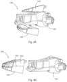
- the lighting mounting 140 further comprises a mounting body 156 having an opening 158.
- the mounting body 156 is configured to be attached to a body of the vehicle (not illustrated).
- the opening 158 is configured to substantially match an opening in the body of the vehicle (not illustrated) and further to expose the lighting unit 142.
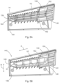
- the cover unit 100 is configured to selectively cover (see Figure 5A ) or un-cover or expose, respectively, (see Figure 5B ) the opening 158.
- the lighting mounting 140 shown in Figure 5A and 5B is an example for a headlamp mounting.
- first axial end 146 of the second cover element 144 is moved about half of the distance of height h2 in the height direction H by the third driving mechanism 150, and the second axial end 148 of the second cover element 144 is moved about half of the distance of height h2 in the height direction H by the fourth driving mechanism 152 to uncover a second half of the opening 158 (in Figure 5B : a lower half of the opening 158).
- the first cover element 102 covers more than half of the opening 158 resulting in the second cover element 144 covering the remaining part of the opening 158, or that the first cover element 102 covers less than half of the opening 158 resulting in the second cover element 144 covering the remaining part of the opening 158.
- the opening 158 may have other contours and/or shapes, such as a triangular contour, a trapezoidal contour etc.
Landscapes
- Engineering & Computer Science (AREA)
- General Engineering & Computer Science (AREA)
- Mechanical Engineering (AREA)
- Non-Portable Lighting Devices Or Systems Thereof (AREA)
Claims (13)
- Abdeckeinheit (100) zum selektiven Abdecken einer Öffnung in einer Struktur, umfassend:zumindest ein erstes Abdeckelement (102) mit einem ersten axialen Ende (104), das mit einem ersten Antriebsmechanismus (108) verbunden ist, und einem zweiten axialen Ende (106), das mit einem zweiten Antriebsmechanismus (110) verbunden ist;wobei der erste Antriebsmechanismus (108) und der zweite Antriebsmechanismus (110) so eingerichtet sind, dass sie das erste Abdeckelement (102) zwischen einer geschlossenen Position und einer geöffneten Position bewegen;wobei sowohl der erste Antriebsmechanismus (108) als auch der zweite Antriebsmechanismus (110) individuell gesteuert werden, dadurch gekennzeichnet, dass der erste und der zweite Antriebsmechanismus (108, 110) Folgendes umfassen:einen Arm (112), der so eingerichtet ist, dass er rotierbar mit der Struktur gekoppelt ist,zumindest eine Antriebseinheit, die eingerichtet ist, eine Bewegung des Arms (112) anzutreiben, undein Gelenk (122), das so eingerichtet ist, dass es den Arm (112) mit dem jeweiligen axialen Ende (104, 106) des ersten Abdeckelements (102) koppelt, wobei das Gelenk (122) so eingerichtet ist, dass es eine zweiachsige Drehung und eine lineare Achsenbewegung ermöglicht, wobei die Achsen unterschiedlich und nicht parallel zueinander sind,wobei das Gelenk (122) so eingerichtet ist, dass das erste axiale Ende (104) und das zweite axiale Ende (106) des ersten Abdeckelements (102) während einer Öffnungsbewegung und/oder einer Schließbewegung unterschiedlich bewegt werden können.
- Abdeckeinheit (100) nach Anspruch 1, ferner umfassend:ein zweites Abdeckelement (144) mit einem ersten axialen Ende (146), das mit einem dritten Antriebsmechanismus (150) gekoppelt ist, und einem zweiten axialen Ende (148), das mit einem vierten Antriebsmechanismus (152) gekoppelt ist;wobei der dritte Antriebsmechanismus (150) und der vierte Antriebsmechanismus (152) so eingerichtet sind, dass sie das zweite Abdeckelement (144) zwischen einer geschlossenen Position und einer geöffneten Position bewegen;wobei sowohl der dritte Antriebsmechanismus (150) als auch der vierte Antriebsmechanismus (152) individuell gesteuert werden und umfassen:einen Arm (112), der so eingerichtet ist, dass er rotierbar mit der Struktur gekoppelt ist,zumindest eine Antriebseinheit, die eingerichtet ist, um eine Bewegung des Arms (112) anzutreiben, undein Gelenk (122), das so eingerichtet ist, dass es den Arm (112) mit dem jeweiligen axialen Ende (146, 148) des zweiten Abdeckelements (144) koppelt, wobei das Gelenk (122) so eingerichtet ist, dass es eine zweiachsige Drehung und eine lineare Achsenbewegung ermöglicht, wobei die Achsen unterschiedlich und nicht parallel zueinander sind,wobei das Gelenk (122) so eingerichtet ist, dass das erste axiale Ende (146) und das zweite axiale Ende (148) des zweiten Abdeckelements (144) während einer Öffnungsbewegung und/oder einer Schließbewegung unterschiedlich bewegt werden können,wobei der erste Antriebsmechanismus (108), der zweite Antriebsmechanismus (100), der dritte Antriebsmechanismus (150) und der vierte Antriebsmechanismus (152) so eingerichtet sind, dass sie an der Struktur befestigt werden können,wobei das erste Abdeckelement (102) und das zweite Abdeckelement (144) so eingerichtet sind, dass sie einander in der geschlossenen Position entlang einer Kontaktlinie (154) berühren, um die Öffnung abzudecken, undwobei das erste Abdeckelement (102) und das zweite Abdeckelement (144) so eingerichtet sind, dass sie in der geöffneten Position voneinander beabstandet sind, um die Öffnung freizulegen.
- Abdeckeinheit (100) nach Anspruch 1 oder 2, wobei während der Öffnungsbewegung das erste axiale Ende (104) des ersten Abdeckelements (102) eine kürzere Strecke als das zweite axiale Ende (106) des ersten Abdeckelements (102) bewegt wird.
- Abdeckeinheit (100) nach einem der Ansprüche 1 bis 3, wobei während der Öffnungsbewegung das erste axiale Ende (1146) des zweiten Abdeckelements (144) um eine kürzere Strecke als das zweite axiale Ende (148) des zweiten Abdeckelements (144) bewegt wird.
- Abdeckeinheit (100) nach einem der Ansprüche 1 bis 4, wobei sowohl der erste Antriebsmechanismus (108) als auch der zweite Antriebsmechanismus (110) eingerichtet ist, das erste Abdeckelement (102) in zumindest zwei unterschiedliche räumliche Richtungen zu bewegen.
- Abdeckeinheit (100) nach einem der Ansprüche 2 bis 5, wobei der dritte Antriebsmechanismus (150) und der vierte Antriebsmechanismus (152) jeweils so eingerichtet sind, dass sie das zweite Abdeckelement (144) in mindestens zwei unterschiedliche Raumrichtungen bewegen.
- Verwendung der Abdeckeinheit (100) nach einem der Ansprüche 1 bis 6 zum Abdecken und/oder Freigeben einer Öffnung für eine Beleuchtung (142) eines Fahrzeugs.
- Beleuchtungshalterung (140) für ein Fahrzeug, umfassend:einen Befestigungskörper (156) mit einer Öffnung (158),eine Beleuchtungseinheit (142), die zumindest eine Lichtquelle umfasst, die so eingerichtet ist, dass sie in der Öffnung (158) des Montagekörpers (156) freigelegt werden kann, undeine Abdeckeinheit (100) nach einem der Ansprüche 1 bis 6, die so eingerichtet ist, dass sie die Öffnung (158) abdeckt oder freilegt.
- Beleuchtungshalterung (140) nach Anspruch 8, wobei die Öffnung (158) eine im Wesentlichen nicht rechteckige Form aufweist.
- Beleuchtungshalterung (140) nach Anspruch 8 oder 9, wobei die Öffnung (158) so eingerichtet ist, dass sie in eine Öffnung in der Karosserie des Fahrzeugs passt.
- Beleuchtungshalterung (140) nach einem der Ansprüche 8 bis 10, wobei die Beleuchtungseinheit (142) ferner eine Antriebseinheit umfasst, die so eingerichtet ist, dass sie die Beleuchtungseinheit (142) in Richtung der Öffnung (158) bewegt und/oder die Beleuchtungseinheit (142) aus der Öffnung (158) zurückzieht.
- Beleuchtungshalterung (140) nach einem der Ansprüche 8 bis 11, wobei die Antriebseinheit so eingerichtet ist, dass sie die Beleuchtungseinheit (142) während einer Schließbewegung der Abdeckelemente (102, 144) zurückzieht und/oder die Beleuchtungseinheit (142) während einer Öffnungsbewegung der Abdeckelemente (102, 144) in Richtung der Öffnung (158) bewegt.
- Beleuchtungshalterung (140) nach einem der Ansprüche 8 bis 12, wobei die Beleuchtungseinheit (142) ferner mehrere Lichtquellen umfasst.
Priority Applications (3)
| Application Number | Priority Date | Filing Date | Title |
|---|---|---|---|
| EP21202331.1A EP4166392B1 (de) | 2021-10-13 | 2021-10-13 | Abdeckeinheit und beleuchtungsbefestigung für ein fahrzeug |
| US17/942,427 US11781722B2 (en) | 2021-10-13 | 2022-09-12 | Cover unit and lighting mounting for vehicle |
| CN202211254341.2A CN115959029A (zh) | 2021-10-13 | 2022-10-13 | 用于车辆的遮盖单元和灯具支座 |
Applications Claiming Priority (1)
| Application Number | Priority Date | Filing Date | Title |
|---|---|---|---|
| EP21202331.1A EP4166392B1 (de) | 2021-10-13 | 2021-10-13 | Abdeckeinheit und beleuchtungsbefestigung für ein fahrzeug |
Publications (2)
| Publication Number | Publication Date |
|---|---|
| EP4166392A1 EP4166392A1 (de) | 2023-04-19 |
| EP4166392B1 true EP4166392B1 (de) | 2023-12-20 |
Family
ID=78179220
Family Applications (1)
| Application Number | Title | Priority Date | Filing Date |
|---|---|---|---|
| EP21202331.1A Active EP4166392B1 (de) | 2021-10-13 | 2021-10-13 | Abdeckeinheit und beleuchtungsbefestigung für ein fahrzeug |
Country Status (3)
| Country | Link |
|---|---|
| US (1) | US11781722B2 (de) |
| EP (1) | EP4166392B1 (de) |
| CN (1) | CN115959029A (de) |
Family Cites Families (11)
| Publication number | Priority date | Publication date | Assignee | Title |
|---|---|---|---|---|
| US3387125A (en) * | 1965-10-13 | 1968-06-04 | Gen Motors Corp | Vehicle headlamp assembly |
| JPS59192632A (ja) * | 1983-04-15 | 1984-11-01 | Mazda Motor Corp | リトラクタブルヘツドランプ |
| US4602319A (en) * | 1983-04-15 | 1986-07-22 | Mazda Motor Corporation | Retractable head-light device for automobiles |
| JPS59192633A (ja) * | 1983-04-15 | 1984-11-01 | Mazda Motor Corp | 自動車用ヘツドランプ |
| JPS61175135A (ja) * | 1985-01-30 | 1986-08-06 | Yukio Kawakami | 自動車の灯火装置 |
| DE10057421B4 (de) * | 2000-11-20 | 2006-01-12 | Trw Automotive Electronics & Components Gmbh & Co. Kg | Luftaustritt für Belüftungsanlagen |
| CN201158334Y (zh) * | 2007-12-25 | 2008-12-03 | 比亚迪股份有限公司 | 车灯随动转向系统 |
| US9416933B2 (en) * | 2013-09-27 | 2016-08-16 | Valeo North America, Inc. | Multi-function LED headlamp |
| KR20160020936A (ko) * | 2014-08-14 | 2016-02-24 | 강주일 | 경광등 리프트 |
| US11346519B2 (en) * | 2018-12-03 | 2022-05-31 | Volvo Car Corporation | Vehicle light assembly including a movable light signature member |
| DE102020104677A1 (de) * | 2020-02-21 | 2021-08-26 | Marelli Automotive Lighting Reutlingen (Germany) GmbH | Kraftfahrzeugscheinwerfer |
-
2021
- 2021-10-13 EP EP21202331.1A patent/EP4166392B1/de active Active
-
2022
- 2022-09-12 US US17/942,427 patent/US11781722B2/en active Active
- 2022-10-13 CN CN202211254341.2A patent/CN115959029A/zh active Pending
Also Published As
| Publication number | Publication date |
|---|---|
| EP4166392A1 (de) | 2023-04-19 |
| US11781722B2 (en) | 2023-10-10 |
| US20230109766A1 (en) | 2023-04-13 |
| CN115959029A (zh) | 2023-04-14 |
Similar Documents
| Publication | Publication Date | Title |
|---|---|---|
| US7441790B2 (en) | Deployable step and body-side assembly for a vehicle | |
| JP6998091B1 (ja) | 可動型前照灯カウル | |
| EP2181890B1 (de) | Fahrzeugscheinwerfer | |
| US20080074895A1 (en) | Convertible vehicle roof having a lamp | |
| JP2000057824A (ja) | 車輌用前照灯 | |
| US7575351B2 (en) | Vehicular headlamp | |
| US20210269102A1 (en) | Active aerodynamics liftgate spoiler design with multi 4 bar kinematic linkages | |
| KR20030047656A (ko) | 차량용 등구 | |
| US11781722B2 (en) | Cover unit and lighting mounting for vehicle | |
| CN106004684A (zh) | 车辆用脚踏板 | |
| US11846399B2 (en) | Lighting device comprising a movable signaling module and a movable lighting module | |
| CN110816393A (zh) | 灯光联调机构 | |
| JP6769911B2 (ja) | 車両用サンバイザ | |
| CA2050134A1 (en) | Manually actuated vehicle spotlight | |
| KR101058334B1 (ko) | 차량용 램프의 전구 고정구조 | |
| JP2004175293A (ja) | 自動車用サンバイザ | |
| KR100501653B1 (ko) | 맵기능과 룸기능을 동시에 갖는 오버헤드 콘솔램프 | |
| JP7822542B1 (ja) | 車両用ドア開閉装置 | |
| KR100282865B1 (ko) | 차량의 후드 스테이 | |
| CN217423109U (zh) | 灯光模组及车辆 | |
| JP4628968B2 (ja) | 車両用サンバイザ | |
| JP2003178608A (ja) | 車両用灯具 | |
| KR200151748Y1 (ko) | 자동차용 헤드램프의 조사각 조절구조 | |
| JP2024098579A (ja) | スライドドア支持機構 | |
| JP6726091B2 (ja) | 車両用ヘッドライト装置 |
Legal Events
| Date | Code | Title | Description |
|---|---|---|---|
| PUAI | Public reference made under article 153(3) epc to a published international application that has entered the european phase |
Free format text: ORIGINAL CODE: 0009012 |
|
| STAA | Information on the status of an ep patent application or granted ep patent |
Free format text: STATUS: REQUEST FOR EXAMINATION WAS MADE |
|
| 17P | Request for examination filed |
Effective date: 20220629 |
|
| AK | Designated contracting states |
Kind code of ref document: A1 Designated state(s): AL AT BE BG CH CY CZ DE DK EE ES FI FR GB GR HR HU IE IS IT LI LT LU LV MC MK MT NL NO PL PT RO RS SE SI SK SM TR |
|
| RIC1 | Information provided on ipc code assigned before grant |
Ipc: F16C 11/02 20060101ALN20230417BHEP Ipc: B60Q 1/00 20060101ALN20230417BHEP Ipc: F16C 31/02 20060101ALI20230417BHEP Ipc: F16C 11/04 20060101ALI20230417BHEP Ipc: B60Q 1/05 20060101ALI20230417BHEP Ipc: B60Q 1/26 20060101AFI20230417BHEP |
|
| RIC1 | Information provided on ipc code assigned before grant |
Ipc: F16C 11/02 20060101ALN20230511BHEP Ipc: B60Q 1/00 20060101ALN20230511BHEP Ipc: F16C 31/02 20060101ALI20230511BHEP Ipc: F16C 11/04 20060101ALI20230511BHEP Ipc: B60Q 1/05 20060101ALI20230511BHEP Ipc: B60Q 1/26 20060101AFI20230511BHEP |
|
| RIC1 | Information provided on ipc code assigned before grant |
Ipc: F16C 11/02 20060101ALN20230515BHEP Ipc: B60Q 1/00 20060101ALN20230515BHEP Ipc: F16C 31/02 20060101ALI20230515BHEP Ipc: F16C 11/04 20060101ALI20230515BHEP Ipc: B60Q 1/05 20060101ALI20230515BHEP Ipc: B60Q 1/26 20060101AFI20230515BHEP |
|
| RIC1 | Information provided on ipc code assigned before grant |
Ipc: F16C 11/02 20060101ALN20230525BHEP Ipc: B60Q 1/00 20060101ALN20230525BHEP Ipc: F16C 31/02 20060101ALI20230525BHEP Ipc: F16C 11/04 20060101ALI20230525BHEP Ipc: B60Q 1/05 20060101ALI20230525BHEP Ipc: B60Q 1/26 20060101AFI20230525BHEP |
|
| GRAP | Despatch of communication of intention to grant a patent |
Free format text: ORIGINAL CODE: EPIDOSNIGR1 |
|
| STAA | Information on the status of an ep patent application or granted ep patent |
Free format text: STATUS: GRANT OF PATENT IS INTENDED |
|
| RIC1 | Information provided on ipc code assigned before grant |
Ipc: F16C 11/02 20060101ALN20230612BHEP Ipc: B60Q 1/00 20060101ALN20230612BHEP Ipc: F16C 31/02 20060101ALI20230612BHEP Ipc: F16C 11/04 20060101ALI20230612BHEP Ipc: B60Q 1/05 20060101ALI20230612BHEP Ipc: B60Q 1/26 20060101AFI20230612BHEP |
|
| INTG | Intention to grant announced |
Effective date: 20230707 |
|
| GRAS | Grant fee paid |
Free format text: ORIGINAL CODE: EPIDOSNIGR3 |
|
| GRAA | (expected) grant |
Free format text: ORIGINAL CODE: 0009210 |
|
| STAA | Information on the status of an ep patent application or granted ep patent |
Free format text: STATUS: THE PATENT HAS BEEN GRANTED |
|
| AK | Designated contracting states |
Kind code of ref document: B1 Designated state(s): AL AT BE BG CH CY CZ DE DK EE ES FI FR GB GR HR HU IE IS IT LI LT LU LV MC MK MT NL NO PL PT RO RS SE SI SK SM TR |
|
| REG | Reference to a national code |
Ref country code: GB Ref legal event code: FG4D |
|
| REG | Reference to a national code |
Ref country code: DE Ref legal event code: R096 Ref document number: 602021007857 Country of ref document: DE |
|
| REG | Reference to a national code |
Ref country code: CH Ref legal event code: EP |
|
| REG | Reference to a national code |
Ref country code: IE Ref legal event code: FG4D |
|
| P01 | Opt-out of the competence of the unified patent court (upc) registered |
Effective date: 20231219 |
|
| PG25 | Lapsed in a contracting state [announced via postgrant information from national office to epo] |
Ref country code: GR Free format text: LAPSE BECAUSE OF FAILURE TO SUBMIT A TRANSLATION OF THE DESCRIPTION OR TO PAY THE FEE WITHIN THE PRESCRIBED TIME-LIMIT Effective date: 20240321 |
|
| REG | Reference to a national code |
Ref country code: LT Ref legal event code: MG9D |
|
| PG25 | Lapsed in a contracting state [announced via postgrant information from national office to epo] |
Ref country code: LT Free format text: LAPSE BECAUSE OF FAILURE TO SUBMIT A TRANSLATION OF THE DESCRIPTION OR TO PAY THE FEE WITHIN THE PRESCRIBED TIME-LIMIT Effective date: 20231220 |
|
| REG | Reference to a national code |
Ref country code: NL Ref legal event code: MP Effective date: 20231220 |
|
| PG25 | Lapsed in a contracting state [announced via postgrant information from national office to epo] |
Ref country code: ES Free format text: LAPSE BECAUSE OF FAILURE TO SUBMIT A TRANSLATION OF THE DESCRIPTION OR TO PAY THE FEE WITHIN THE PRESCRIBED TIME-LIMIT Effective date: 20231220 |
|
| PG25 | Lapsed in a contracting state [announced via postgrant information from national office to epo] |
Ref country code: LT Free format text: LAPSE BECAUSE OF FAILURE TO SUBMIT A TRANSLATION OF THE DESCRIPTION OR TO PAY THE FEE WITHIN THE PRESCRIBED TIME-LIMIT Effective date: 20231220 Ref country code: GR Free format text: LAPSE BECAUSE OF FAILURE TO SUBMIT A TRANSLATION OF THE DESCRIPTION OR TO PAY THE FEE WITHIN THE PRESCRIBED TIME-LIMIT Effective date: 20240321 Ref country code: FI Free format text: LAPSE BECAUSE OF FAILURE TO SUBMIT A TRANSLATION OF THE DESCRIPTION OR TO PAY THE FEE WITHIN THE PRESCRIBED TIME-LIMIT Effective date: 20231220 Ref country code: ES Free format text: LAPSE BECAUSE OF FAILURE TO SUBMIT A TRANSLATION OF THE DESCRIPTION OR TO PAY THE FEE WITHIN THE PRESCRIBED TIME-LIMIT Effective date: 20231220 Ref country code: BG Free format text: LAPSE BECAUSE OF FAILURE TO SUBMIT A TRANSLATION OF THE DESCRIPTION OR TO PAY THE FEE WITHIN THE PRESCRIBED TIME-LIMIT Effective date: 20240320 |
|
| REG | Reference to a national code |
Ref country code: AT Ref legal event code: MK05 Ref document number: 1642223 Country of ref document: AT Kind code of ref document: T Effective date: 20231220 |
|
| PG25 | Lapsed in a contracting state [announced via postgrant information from national office to epo] |
Ref country code: NL Free format text: LAPSE BECAUSE OF FAILURE TO SUBMIT A TRANSLATION OF THE DESCRIPTION OR TO PAY THE FEE WITHIN THE PRESCRIBED TIME-LIMIT Effective date: 20231220 |
|
| PG25 | Lapsed in a contracting state [announced via postgrant information from national office to epo] |
Ref country code: SE Free format text: LAPSE BECAUSE OF FAILURE TO SUBMIT A TRANSLATION OF THE DESCRIPTION OR TO PAY THE FEE WITHIN THE PRESCRIBED TIME-LIMIT Effective date: 20231220 Ref country code: RS Free format text: LAPSE BECAUSE OF FAILURE TO SUBMIT A TRANSLATION OF THE DESCRIPTION OR TO PAY THE FEE WITHIN THE PRESCRIBED TIME-LIMIT Effective date: 20231220 Ref country code: NO Free format text: LAPSE BECAUSE OF FAILURE TO SUBMIT A TRANSLATION OF THE DESCRIPTION OR TO PAY THE FEE WITHIN THE PRESCRIBED TIME-LIMIT Effective date: 20240320 Ref country code: NL Free format text: LAPSE BECAUSE OF FAILURE TO SUBMIT A TRANSLATION OF THE DESCRIPTION OR TO PAY THE FEE WITHIN THE PRESCRIBED TIME-LIMIT Effective date: 20231220 Ref country code: LV Free format text: LAPSE BECAUSE OF FAILURE TO SUBMIT A TRANSLATION OF THE DESCRIPTION OR TO PAY THE FEE WITHIN THE PRESCRIBED TIME-LIMIT Effective date: 20231220 Ref country code: HR Free format text: LAPSE BECAUSE OF FAILURE TO SUBMIT A TRANSLATION OF THE DESCRIPTION OR TO PAY THE FEE WITHIN THE PRESCRIBED TIME-LIMIT Effective date: 20231220 |
|
| PG25 | Lapsed in a contracting state [announced via postgrant information from national office to epo] |
Ref country code: IS Free format text: LAPSE BECAUSE OF FAILURE TO SUBMIT A TRANSLATION OF THE DESCRIPTION OR TO PAY THE FEE WITHIN THE PRESCRIBED TIME-LIMIT Effective date: 20240420 |
|
| PG25 | Lapsed in a contracting state [announced via postgrant information from national office to epo] |
Ref country code: CZ Free format text: LAPSE BECAUSE OF FAILURE TO SUBMIT A TRANSLATION OF THE DESCRIPTION OR TO PAY THE FEE WITHIN THE PRESCRIBED TIME-LIMIT Effective date: 20231220 Ref country code: AT Free format text: LAPSE BECAUSE OF FAILURE TO SUBMIT A TRANSLATION OF THE DESCRIPTION OR TO PAY THE FEE WITHIN THE PRESCRIBED TIME-LIMIT Effective date: 20231220 |
|
| PG25 | Lapsed in a contracting state [announced via postgrant information from national office to epo] |
Ref country code: SK Free format text: LAPSE BECAUSE OF FAILURE TO SUBMIT A TRANSLATION OF THE DESCRIPTION OR TO PAY THE FEE WITHIN THE PRESCRIBED TIME-LIMIT Effective date: 20231220 |
|
| PG25 | Lapsed in a contracting state [announced via postgrant information from national office to epo] |
Ref country code: SM Free format text: LAPSE BECAUSE OF FAILURE TO SUBMIT A TRANSLATION OF THE DESCRIPTION OR TO PAY THE FEE WITHIN THE PRESCRIBED TIME-LIMIT Effective date: 20231220 Ref country code: SK Free format text: LAPSE BECAUSE OF FAILURE TO SUBMIT A TRANSLATION OF THE DESCRIPTION OR TO PAY THE FEE WITHIN THE PRESCRIBED TIME-LIMIT Effective date: 20231220 Ref country code: RO Free format text: LAPSE BECAUSE OF FAILURE TO SUBMIT A TRANSLATION OF THE DESCRIPTION OR TO PAY THE FEE WITHIN THE PRESCRIBED TIME-LIMIT Effective date: 20231220 Ref country code: IT Free format text: LAPSE BECAUSE OF FAILURE TO SUBMIT A TRANSLATION OF THE DESCRIPTION OR TO PAY THE FEE WITHIN THE PRESCRIBED TIME-LIMIT Effective date: 20231220 Ref country code: IS Free format text: LAPSE BECAUSE OF FAILURE TO SUBMIT A TRANSLATION OF THE DESCRIPTION OR TO PAY THE FEE WITHIN THE PRESCRIBED TIME-LIMIT Effective date: 20240420 Ref country code: EE Free format text: LAPSE BECAUSE OF FAILURE TO SUBMIT A TRANSLATION OF THE DESCRIPTION OR TO PAY THE FEE WITHIN THE PRESCRIBED TIME-LIMIT Effective date: 20231220 Ref country code: CZ Free format text: LAPSE BECAUSE OF FAILURE TO SUBMIT A TRANSLATION OF THE DESCRIPTION OR TO PAY THE FEE WITHIN THE PRESCRIBED TIME-LIMIT Effective date: 20231220 Ref country code: AT Free format text: LAPSE BECAUSE OF FAILURE TO SUBMIT A TRANSLATION OF THE DESCRIPTION OR TO PAY THE FEE WITHIN THE PRESCRIBED TIME-LIMIT Effective date: 20231220 |
|
| PG25 | Lapsed in a contracting state [announced via postgrant information from national office to epo] |
Ref country code: PT Free format text: LAPSE BECAUSE OF FAILURE TO SUBMIT A TRANSLATION OF THE DESCRIPTION OR TO PAY THE FEE WITHIN THE PRESCRIBED TIME-LIMIT Effective date: 20240422 Ref country code: PL Free format text: LAPSE BECAUSE OF FAILURE TO SUBMIT A TRANSLATION OF THE DESCRIPTION OR TO PAY THE FEE WITHIN THE PRESCRIBED TIME-LIMIT Effective date: 20231220 |
|
| PG25 | Lapsed in a contracting state [announced via postgrant information from national office to epo] |
Ref country code: PT Free format text: LAPSE BECAUSE OF FAILURE TO SUBMIT A TRANSLATION OF THE DESCRIPTION OR TO PAY THE FEE WITHIN THE PRESCRIBED TIME-LIMIT Effective date: 20240422 Ref country code: PL Free format text: LAPSE BECAUSE OF FAILURE TO SUBMIT A TRANSLATION OF THE DESCRIPTION OR TO PAY THE FEE WITHIN THE PRESCRIBED TIME-LIMIT Effective date: 20231220 |
|
| REG | Reference to a national code |
Ref country code: DE Ref legal event code: R097 Ref document number: 602021007857 Country of ref document: DE |
|
| PG25 | Lapsed in a contracting state [announced via postgrant information from national office to epo] |
Ref country code: DK Free format text: LAPSE BECAUSE OF FAILURE TO SUBMIT A TRANSLATION OF THE DESCRIPTION OR TO PAY THE FEE WITHIN THE PRESCRIBED TIME-LIMIT Effective date: 20231220 |
|
| PLBE | No opposition filed within time limit |
Free format text: ORIGINAL CODE: 0009261 |
|
| STAA | Information on the status of an ep patent application or granted ep patent |
Free format text: STATUS: NO OPPOSITION FILED WITHIN TIME LIMIT |
|
| PG25 | Lapsed in a contracting state [announced via postgrant information from national office to epo] |
Ref country code: SI Free format text: LAPSE BECAUSE OF FAILURE TO SUBMIT A TRANSLATION OF THE DESCRIPTION OR TO PAY THE FEE WITHIN THE PRESCRIBED TIME-LIMIT Effective date: 20231220 |
|
| PG25 | Lapsed in a contracting state [announced via postgrant information from national office to epo] |
Ref country code: SI Free format text: LAPSE BECAUSE OF FAILURE TO SUBMIT A TRANSLATION OF THE DESCRIPTION OR TO PAY THE FEE WITHIN THE PRESCRIBED TIME-LIMIT Effective date: 20231220 Ref country code: DK Free format text: LAPSE BECAUSE OF FAILURE TO SUBMIT A TRANSLATION OF THE DESCRIPTION OR TO PAY THE FEE WITHIN THE PRESCRIBED TIME-LIMIT Effective date: 20231220 |
|
| 26N | No opposition filed |
Effective date: 20240923 |
|
| REG | Reference to a national code |
Ref country code: CH Ref legal event code: PL |
|
| PG25 | Lapsed in a contracting state [announced via postgrant information from national office to epo] |
Ref country code: MC Free format text: LAPSE BECAUSE OF FAILURE TO SUBMIT A TRANSLATION OF THE DESCRIPTION OR TO PAY THE FEE WITHIN THE PRESCRIBED TIME-LIMIT Effective date: 20231220 |
|
| PG25 | Lapsed in a contracting state [announced via postgrant information from national office to epo] |
Ref country code: BE Free format text: LAPSE BECAUSE OF NON-PAYMENT OF DUE FEES Effective date: 20241031 Ref country code: LU Free format text: LAPSE BECAUSE OF NON-PAYMENT OF DUE FEES Effective date: 20241013 |
|
| PG25 | Lapsed in a contracting state [announced via postgrant information from national office to epo] |
Ref country code: CH Free format text: LAPSE BECAUSE OF NON-PAYMENT OF DUE FEES Effective date: 20241031 |
|
| REG | Reference to a national code |
Ref country code: BE Ref legal event code: MM Effective date: 20241031 |
|
| PGFP | Annual fee paid to national office [announced via postgrant information from national office to epo] |
Ref country code: GB Payment date: 20250923 Year of fee payment: 5 |
|
| PGFP | Annual fee paid to national office [announced via postgrant information from national office to epo] |
Ref country code: FR Payment date: 20250924 Year of fee payment: 5 |
|
| PG25 | Lapsed in a contracting state [announced via postgrant information from national office to epo] |
Ref country code: IE Free format text: LAPSE BECAUSE OF NON-PAYMENT OF DUE FEES Effective date: 20241013 |
|
| PGFP | Annual fee paid to national office [announced via postgrant information from national office to epo] |
Ref country code: DE Payment date: 20250923 Year of fee payment: 5 |
|
| PG25 | Lapsed in a contracting state [announced via postgrant information from national office to epo] |
Ref country code: CY Free format text: LAPSE BECAUSE OF FAILURE TO SUBMIT A TRANSLATION OF THE DESCRIPTION OR TO PAY THE FEE WITHIN THE PRESCRIBED TIME-LIMIT; INVALID AB INITIO Effective date: 20211013 |
|
| PG25 | Lapsed in a contracting state [announced via postgrant information from national office to epo] |
Ref country code: HU Free format text: LAPSE BECAUSE OF FAILURE TO SUBMIT A TRANSLATION OF THE DESCRIPTION OR TO PAY THE FEE WITHIN THE PRESCRIBED TIME-LIMIT; INVALID AB INITIO Effective date: 20211013 |