EP4166476A1 - Transferroboter, kastenabrufverfahren, frachtkastenladeverfahren und lagerlogistiksystem - Google Patents
Transferroboter, kastenabrufverfahren, frachtkastenladeverfahren und lagerlogistiksystem Download PDFInfo
- Publication number
- EP4166476A1 EP4166476A1 EP21821379.1A EP21821379A EP4166476A1 EP 4166476 A1 EP4166476 A1 EP 4166476A1 EP 21821379 A EP21821379 A EP 21821379A EP 4166476 A1 EP4166476 A1 EP 4166476A1
- Authority
- EP
- European Patent Office
- Prior art keywords
- cargo box
- transfer robot
- telescopic
- plate
- lifting
- Prior art date
- Legal status (The legal status is an assumption and is not a legal conclusion. Google has not performed a legal analysis and makes no representation as to the accuracy of the status listed.)
- Granted
Links
Images




Classifications
-
- B—PERFORMING OPERATIONS; TRANSPORTING
- B65—CONVEYING; PACKING; STORING; HANDLING THIN OR FILAMENTARY MATERIAL
- B65G—TRANSPORT OR STORAGE DEVICES, e.g. CONVEYORS FOR LOADING OR TIPPING, SHOP CONVEYOR SYSTEMS OR PNEUMATIC TUBE CONVEYORS
- B65G1/00—Storing articles, individually or in orderly arrangement, in warehouses or magazines
- B65G1/02—Storage devices
- B65G1/04—Storage devices mechanical
- B65G1/06—Storage devices mechanical with means for presenting articles for removal at predetermined position or level
-
- B—PERFORMING OPERATIONS; TRANSPORTING
- B65—CONVEYING; PACKING; STORING; HANDLING THIN OR FILAMENTARY MATERIAL
- B65G—TRANSPORT OR STORAGE DEVICES, e.g. CONVEYORS FOR LOADING OR TIPPING, SHOP CONVEYOR SYSTEMS OR PNEUMATIC TUBE CONVEYORS
- B65G1/00—Storing articles, individually or in orderly arrangement, in warehouses or magazines
- B65G1/02—Storage devices
- B65G1/04—Storage devices mechanical
-
- B—PERFORMING OPERATIONS; TRANSPORTING
- B65—CONVEYING; PACKING; STORING; HANDLING THIN OR FILAMENTARY MATERIAL
- B65G—TRANSPORT OR STORAGE DEVICES, e.g. CONVEYORS FOR LOADING OR TIPPING, SHOP CONVEYOR SYSTEMS OR PNEUMATIC TUBE CONVEYORS
- B65G1/00—Storing articles, individually or in orderly arrangement, in warehouses or magazines
- B65G1/02—Storage devices
- B65G1/04—Storage devices mechanical
- B65G1/0492—Storage devices mechanical with cars adapted to travel in storage aisles
-
- B—PERFORMING OPERATIONS; TRANSPORTING
- B25—HAND TOOLS; PORTABLE POWER-DRIVEN TOOLS; MANIPULATORS
- B25J—MANIPULATORS; CHAMBERS PROVIDED WITH MANIPULATION DEVICES
- B25J11/00—Manipulators not otherwise provided for
- B25J11/008—Manipulators for service tasks
-
- B—PERFORMING OPERATIONS; TRANSPORTING
- B25—HAND TOOLS; PORTABLE POWER-DRIVEN TOOLS; MANIPULATORS
- B25J—MANIPULATORS; CHAMBERS PROVIDED WITH MANIPULATION DEVICES
- B25J18/00—Arms
- B25J18/02—Arms extensible
- B25J18/025—Arms extensible telescopic
-
- B—PERFORMING OPERATIONS; TRANSPORTING
- B25—HAND TOOLS; PORTABLE POWER-DRIVEN TOOLS; MANIPULATORS
- B25J—MANIPULATORS; CHAMBERS PROVIDED WITH MANIPULATION DEVICES
- B25J5/00—Manipulators mounted on wheels or on carriages
-
- B—PERFORMING OPERATIONS; TRANSPORTING
- B25—HAND TOOLS; PORTABLE POWER-DRIVEN TOOLS; MANIPULATORS
- B25J—MANIPULATORS; CHAMBERS PROVIDED WITH MANIPULATION DEVICES
- B25J5/00—Manipulators mounted on wheels or on carriages
- B25J5/007—Manipulators mounted on wheels or on carriages mounted on wheels
-
- B—PERFORMING OPERATIONS; TRANSPORTING
- B25—HAND TOOLS; PORTABLE POWER-DRIVEN TOOLS; MANIPULATORS
- B25J—MANIPULATORS; CHAMBERS PROVIDED WITH MANIPULATION DEVICES
- B25J9/00—Program-controlled manipulators
- B25J9/0009—Constructional details, e.g. manipulator supports, bases
-
- B—PERFORMING OPERATIONS; TRANSPORTING
- B25—HAND TOOLS; PORTABLE POWER-DRIVEN TOOLS; MANIPULATORS
- B25J—MANIPULATORS; CHAMBERS PROVIDED WITH MANIPULATION DEVICES
- B25J9/00—Program-controlled manipulators
- B25J9/02—Program-controlled manipulators characterised by movement of the arms, e.g. cartesian coordinate type
- B25J9/023—Cartesian coordinate type
-
- B—PERFORMING OPERATIONS; TRANSPORTING
- B25—HAND TOOLS; PORTABLE POWER-DRIVEN TOOLS; MANIPULATORS
- B25J—MANIPULATORS; CHAMBERS PROVIDED WITH MANIPULATION DEVICES
- B25J9/00—Program-controlled manipulators
- B25J9/10—Program-controlled manipulators characterised by positioning means for manipulator elements
- B25J9/104—Program-controlled manipulators characterised by positioning means for manipulator elements with cables, chains or ribbons
-
- B—PERFORMING OPERATIONS; TRANSPORTING
- B65—CONVEYING; PACKING; STORING; HANDLING THIN OR FILAMENTARY MATERIAL
- B65G—TRANSPORT OR STORAGE DEVICES, e.g. CONVEYORS FOR LOADING OR TIPPING, SHOP CONVEYOR SYSTEMS OR PNEUMATIC TUBE CONVEYORS
- B65G1/00—Storing articles, individually or in orderly arrangement, in warehouses or magazines
- B65G1/02—Storage devices
- B65G1/04—Storage devices mechanical
- B65G1/137—Storage devices mechanical with arrangements or automatic control means for selecting which articles are to be removed
- B65G1/1373—Storage devices mechanical with arrangements or automatic control means for selecting which articles are to be removed for fulfilling orders in warehouses
- B65G1/1375—Storage devices mechanical with arrangements or automatic control means for selecting which articles are to be removed for fulfilling orders in warehouses the orders being assembled on a commissioning stacker-crane or truck
-
- B—PERFORMING OPERATIONS; TRANSPORTING
- B65—CONVEYING; PACKING; STORING; HANDLING THIN OR FILAMENTARY MATERIAL
- B65G—TRANSPORT OR STORAGE DEVICES, e.g. CONVEYORS FOR LOADING OR TIPPING, SHOP CONVEYOR SYSTEMS OR PNEUMATIC TUBE CONVEYORS
- B65G2201/00—Indexing codes relating to handling devices, e.g. conveyors, characterised by the type of product or load being conveyed or handled
- B65G2201/02—Articles
- B65G2201/0235—Containers
- B65G2201/025—Boxes
Definitions
- the present invention relates to the field of warehousing and logistics, and more particularly, to a transfer robot, a box retrieval method, a cargo box loading method, and a warehouse logistics system.
- FIG. 1 illustrates a robot for transferring cargo boxes in the related art.
- the robot includes a drive unit 100, a cargo box storage unit 200, and a cargo box conveying unit 300.
- the drive unit 100 carries the cargo box storage unit 200 and enables it to move together with the cargo box conveying unit 300.
- the cargo box storage unit 200 includes one or more cargo box storage spaces.
- the cargo box conveying unit 300 is configured to convey cargo boxes 400 between the cargo box storage spaces and the inventory container.
- the cargo box conveying unit 300 includes a frame 310 for placing cargo boxes, a lifting device 320 for driving the cargo boxes 400 up and down, a telescopic fork 330 for driving the cargo boxes 400 to extend and retract, and a rotation device 340 for driving the cargo boxes 400 to rotate.
- the cargo box conveying unit 300 is arranged on the cargo box storage unit 200, a lifting travel of the cargo box conveying unit 300 is limited by a height of the cargo box storage unit 200. Nevertheless, when the inventory container for storing the cargo boxes 400 is high, the height of the cargo box storage unit 200 is increased, which results in a higher center of gravity for the entire robot and reduced stability of movement. Moreover, the increase in the height of the cargo box storage unit 200 allows more cargo boxes to be transferred by the robot at a single time, increasing the operation load of the robot and reducing the transfer efficiency. Meanwhile, when the cargo box storage unit 200 is high, the cargo boxes in an upper part of the cargo box storage unit 200 are difficult to be picked directly by picking personnel, increasing the difficulty of picking by the personnel.
- An objective of the present invention is to provide a transfer robot that improves the efficiency of picking and placing cargo boxes, and enhances the sorting and logistics efficiency.
- Another objective of the present invention is to provide a box retrieval method that improves the efficiency of retrieving cargo boxes by the transfer robot, and enhances improving the sorting and logistics efficiency.
- Another objective of the present invention is to provide a cargo box loading method that improves the efficiency of loading cargo boxes by the transfer robot, and enhances the sorting, loading and logistics efficiency.
- Another objective of the present invention is to provide a warehouse logistics system with improved efficiency.
- the present invention adopts the following technical solutions.
- a transfer robot includes a movable chassis, a door frame vertically arranged on the movable chassis, a temporary storage mechanism, and a cargo box conveying mechanism.
- the temporary storage mechanism and the cargo box conveying mechanism are arranged on the door frame; the temporary storage mechanism has a plurality of temporary storage spaces for temporary storage of cargo boxes; and the cargo box conveying mechanism can transfer the cargo boxes between the temporary storage spaces and inventory containers.
- the temporary storage mechanism includes a plurality of temporary-storage partition plates arranged at intervals along a height direction and detachably connected to the door frame; and each of the plurality of temporary storage spaces is on an upper surface of each of the plurality of temporary-storage partition plates.
- a height position of each of the plurality of temporary-storage partition plates on the door frame is adjustable.
- each of the plurality of temporary-storage partition plates includes a partition plate body arranged horizontally and a connection rod arranged on a lower surface of the partition plate body; and two ends of the connection rod are detachably connected to the door frame.
- a flange is arranged around a periphery of the partition plate body, and the flange protrudes from the upper surface of the temporary-storage partition plate and encloses the temporary storage space with one open end.
- the door frame includes a pair of support columns arranged in parallel and spaced apart from each other; the support columns are arranged vertically; and the temporary storage mechanism and the cargo box conveying mechanism are both connected to the pair of support columns.
- a plurality of pairs of support columns are arranged along the height direction, and two adjacent support columns in the height direction are detachably connected.
- each of the support columns includes a main body plate arranged vertically and reinforcement rods arranged on two opposite sides of the main body plate, each reinforcement rod having a hollow cavity with two open ends; and a connection strip is arranged between the two adjacent support columns in the height direction, and two ends of the connection strip are inserted into respective hollow cavities of upper and lower reinforcement rods of the two adjacent support columns.
- the cargo box conveying mechanism is connected to the door frame through a lifting mechanism; the lifting mechanism is configured to drive the cargo box conveying mechanism to rise and fall vertically; and the lifting mechanism is a self-driven lifting mechanism.
- the lifting mechanism includes a mounting seat, a lifting drive unit, and a lifting transmission assembly, the lifting drive unit and the lifting transmission assembly being on the mounting seat; the door frame includes an auxiliary transmission member; and the lifting drive unit drives the lifting transmission assembly to transmissively cooperate with the auxiliary transmission member, and the lifting mechanism is vertically raised and lowered along the auxiliary transmission member.
- the lifting transmission assembly includes two first lifting synchronization wheels spaced apart along the height direction, and a first lifting synchronous belt wound around the two first lifting synchronization wheels, the first lifting synchronous belt being a double-sided toothed synchronous belt;
- the auxiliary transmission member is a single-sided toothed synchronous belt vertically arranged on the door frame, and the first lifting synchronous belt meshes with the single-sided toothed synchronous belt;
- the lifting drive unit includes a lifting drive motor, and the lifting drive motor is configured to drive one of the two first lifting synchronization wheels to rotate around a horizontal axis.
- the lifting mechanism further includes a lifting guide assembly configured to guide a vertical movement of the lifting mechanism.
- the support column has a receiving groove with an opening facing the other support column; the auxiliary transmission member is arranged on a side groove wall of the receiving groove; and the lifting guide assembly is slidably or rollingly connected to the other opposite groove wall.
- the lifting transmission assembly is connected to each of the two support columns; the lifting mechanism further includes a lifting synchronization transmission assembly; and the lifting drive unit drives two lifting transmission assemblies to act synchronously through the lifting synchronization transmission assembly.
- the mounting seat includes a first mounting plate arranged horizontally and two second mounting plates vertically arranged at both ends of the first mounting plate; the first mounting plate is connected to respective upper ends of the second mounting plates; the lifting transmission assembly is arranged on the corresponding second mounting plate; and the lifting drive unit is arranged on an upper surface of the first mounting plate.
- the cargo box conveying mechanism includes: a transit plate detachably connected to the door frame; a box retrieval assembly configured to toggle the cargo box and move the cargo box between the transit plate and the inventory container; and a telescopic assembly connected to the transit plate and the box retrieval assembly and configured to drive the box retrieval assembly to extend and retract horizontally relative to the transit plate.
- the telescopic assembly is a two-stage synchronous telescopic structure or a three-stage synchronous telescopic structure.
- the telescopic assembly is arranged on each of two opposite sides of the transit plate, and the telescopic assemblies are synchronously driven by a common telescopic drive assembly in cooperation with the telescopic synchronization transmission assembly.
- the transit plate has a first end formed with a cargo box entry-exit port, and a second end provided with a partition plate; and the telescopic drive assembly and the telescopic synchronization transmission assembly are on a side of the partition plate away from the cargo box entry-exit port.
- the cargo box conveying mechanism is connected to the door frame through a rotation mechanism and a lifting mechanism; the rotation mechanism is configured to drive the cargo box conveying mechanism to rotate horizontally; and the lifting mechanism is configured to drive the rotation mechanism and the cargo box conveying mechanism to rise and fall vertically.
- the rotation mechanism and the temporary storage mechanism are on two opposite sides of the door frame.
- the rotation mechanism includes: a support plate arranged horizontally and connected to the lifting mechanism; a rotation transmission assembly arranged between the support plate and a bottom of the cargo box conveying mechanism; and a rotation drive unit connected to the cargo box conveying mechanism and cooperating with the rotation transmission assembly to drive the cargo box conveying mechanism to rotate horizontally relative to the support plate.
- the rotation drive unit includes a rotation drive motor having a vertically arranged drive shaft.
- the rotation transmission assembly includes: a rotation bearing having an inner ring end face connected to the bottom of the cargo box conveying mechanism, and an outer ring end face connected to the support plate, in which an outer ring of the rotation bearing is provided with a synchronous belt gear ring; a rotation synchronization wheel fitted over the output shaft of the rotation drive motor; and a rotation synchronous belt arranged horizontally and wound around the synchronous belt gear ring and the rotation synchronization wheel.
- the bottom of the cargo box conveying mechanism is provided with an accommodating groove that is shaped to match a shape of the rotation synchronous belt, and the rotation synchronous belt is arranged in the accommodating groove.
- a box retrieval method uses a transfer robot to pick up a target cargo box on an inventory container.
- the transfer robot includes a movable chassis, a door frame vertically arranged on the movable chassis, a temporary storage mechanism, and a cargo box conveying mechanism, in which the temporary storage mechanism and the cargo box conveying mechanism are arranged on the door frame.
- the temporary storage mechanism has a plurality of temporary storage spaces for temporary storage of cargo boxes; and the cargo box conveying mechanism transfers the cargo boxes between the temporary storage spaces and inventory containers.
- the box retrieval method includes: picking up the target cargo box right in front of the transfer robot.
- Picking up the target cargo box located right in front of the transfer robot includes steps: raising or lowering the cargo box conveying mechanism to a height of the target cargo box; operating the cargo box conveying mechanism to pick up the target cargo box on the inventory container to the cargo box conveying mechanism; raising or lowering the cargo box conveying mechanism to a height of a height a vacant temporary storage space; and operating the cargo box conveying mechanism to convey the target cargo box on the cargo box conveying mechanism to the vacant temporary storage space.
- the cargo box conveying mechanism is connected to the door frame through a rotation mechanism and a lifting mechanism; the rotation mechanism is configured to drive the cargo box conveying mechanism to rotate horizontally; and the lifting mechanism is configured to drive the rotation mechanism and the cargo box conveying mechanism to rise and fall vertically, in which the rotation mechanism and the temporary storage mechanism are on two opposite sides of the door frame.
- the box retrieval method further includes: operating the rotation mechanism to extend the cargo box conveying mechanism towards the target cargo box.
- the box retrieval method further includes: operating the rotation mechanism to extend the cargo box conveying mechanism towards the temporary storage mechanism.
- the box retrieval method before picking up the target cargo box right in front of the transfer robot, the box retrieval method further includes: assigning a box retrieval task to the transfer robot by a control system; planning a box retrieval path by the control system based on positions of all target cargo boxes during the box retrieval task; and operating the transfer robot to run to the front of each target cargo box sequentially based on the box retrieval path.
- the box retrieval method further includes: determining whether there is an internal cargo box during the box retrieval task, when planning the box retrieval path.
- the internal cargo box is not at the last box retrieval position in the box retrieval path when the internal cargo box exists; and the box retrieval path is the shortest path when the internal cargo box does not exist.
- a cargo box loading method uses a transfer robot to load a cargo box onto a target position of an inventory container.
- the transfer robot includes a movable chassis, a door frame vertically arranged on the movable chassis, a temporary storage mechanism, and a cargo box conveying mechanism, in which the temporary storage mechanism and the cargo box conveying mechanism are arranged on the door frame.
- the temporary storage mechanism has a plurality of temporary storage spaces for temporary storage of cargo boxes; and the cargo box conveying mechanism transfers the cargo boxes between the temporary storage spaces and inventory containers.
- the cargo box loading method includes: raising or lowering the cargo box conveying mechanism to a height of the cargo box corresponding to the target position; operating the cargo box conveying mechanism to transfer the cargo box from the temporary storage space to the cargo box conveying mechanism; raising or lowering the cargo box conveying mechanism to a height of the target position; and operating the cargo box conveying mechanism to convey the cargo box on the cargo box conveying mechanism to the target position.
- the cargo box conveying mechanism is connected to the door frame through a rotation mechanism and a lifting mechanism; the rotation mechanism is configured to drive the cargo box conveying mechanism to rotate horizontally; and the lifting mechanism is configured to drive the rotation mechanism and the cargo box conveying mechanism to rise and fall vertically, in which the rotation mechanism and the temporary storage mechanism are on two opposite sides of the door frame.
- the cargo box loading method further includes: operating the rotation mechanism to extend the cargo box conveying mechanism towards the cargo box.
- the cargo box loading method further includes: operating the rotation mechanism to extend the cargo box conveying mechanism towards the target position.
- a warehouse logistics system includes the above-mentioned transfer robot.
- the present invention has the following beneficial effects.
- the transfer robot For the transfer robot according to the present invention, most structures of the transfer robot are integrated on the door frame by arranging the cargo box conveying mechanism and the temporary storage mechanism on the door frame, which is beneficial to the installation of the cargo box conveying mechanism and the temporary storage mechanism. Meanwhile, since the door frame and the temporary storage mechanism are arranged separately, the lifting height of the cargo box conveying mechanism is not affected by the position of the temporary storage mechanism. That is, the cargo box conveying mechanism may rise to a higher position to pick up or place the cargo box, while the temporary storage mechanism may be arranged at a height suitable for the picking personnel. As a result, the picking personnel can perform sorting conveniently, and the transfer robot can pick up or place cargo boxes of higher inventory containers, which improves the applicability and versatility of the transfer robot.
- the box retrieval method according to the present invention uses the above-mentioned transfer robot to carry out a cargo box retrieval operation, so that the height of the cargo box to be picked up is not limited to the height of the temporary-storage partition plate, improving the applicability and versatility of the box retrieval method. Moreover, the transfer robot can transfer a plurality of cargo boxes at the same time, which improves the transfer efficiency and hence the efficiency of warehouse logistics.
- the cargo box loading method uses the above-mentioned transfer robot to carry out a cargo box loading operation, so that the height of the cargo box to be loaded is not limited to the height of the temporary-storage partition plate, improving the applicability and versatility of the box retrieval method. Moreover, the transfer robot can transfer a plurality of cargo boxes at the same time, which improves the transfer efficiency and hence the efficiency of warehouse logistics.
- the warehouse logistics system uses the above-mentioned transfer robot to transfer cargo boxes, thereby improving the versatility and applicability of the transfer robot, and improving the efficiency of warehouse logistics.
- Reference numerals in Fig. 1 corresponding to the related art include: 100-drive unit; 200-cargo storage unit; 220-pallet; 300-cargo box conveying unit; 310-frame; 320-lifting device; 330-telescopic fork; 340-rotation device; 400-cargo box.
- a structure in which a first feature is "on" or “below” a second feature may include an embodiment in which the first feature is in direct contact with the second feature, and may also include an embodiment in which the first feature and the second feature are not in direct contact with each other, but are contacted via an additional feature formed therebetween.
- a first feature "on,” “above,” or “on top of' a second feature may include an embodiment in which the first feature is right or obliquely “on,” “above,” or “on top of' the second feature, or just means that the first feature is at a height higher than that of the second feature; while a first feature "below,” “under,” or “on bottom of' a second feature may include an embodiment in which the first feature is right or obliquely “below,” “under,” or “on bottom of' the second feature, or just means that the first feature is at a height lower than that of the second feature.
- Fig. 2 is a schematic view of a transfer robot according to a first embodiment of the present invention.
- this embodiment provides a transfer robot for carrying, and picking and placing a cargo box 7, which is mainly used in the warehousing and logistics industry.
- the transfer robot can be used to pick and place and transport the cargo box 7 containing order goods or express deliveries, to implement order-based picking or loading operations.
- the transfer robot can also be applied to other situations where the cargo box 7 or the goods need to be transferred.
- the application of the transfer robot in this embodiment is only exemplary, which is not specifically limited herein.
- the transfer robot includes: a movable chassis 6, a door frame 2 vertically arranged on the movable chassis 6, a temporary storage mechanism on the door frame 2, and a cargo box conveying mechanism 1 on the door frame 2.
- the temporary storage mechanism has a plurality of temporary storage spaces for temporary storage of cargo boxes 7.
- the cargo box conveying mechanism 1 conveys the cargo boxes 7 between the temporary storage spaces and inventory containers.
- the transfer robot in this embodiment further includes at least one of the following: a rotation mechanism 5, a lifting mechanism 3, a detection assembly, and a control system.
- the movable chassis 6 is used to realize movement of the transfer robot on the ground, to realize the transportation of the cargo boxes 7 by the transfer robot.
- the door frame 2 is vertically arranged on the movable chassis 6.
- the temporary storage mechanism has several temporary storage spaces for temporary storage of the cargo boxes 7.
- the rotation mechanism 5 is arranged on the door frame 2, and the cargo box conveying mechanism 1 is connected to the lifting mechanism 3 through the rotation mechanism 5, to allow the cargo box conveying mechanism 1 to rotate on a horizontal plane and rise or fall in a vertical direction.
- the cargo box conveying mechanism 1 is horizontally telescopic to pick up the cargo box 7 in the temporary storage space or in the inventory container.
- the detection assembly is used to detect a working status of the transfer robot and a state of the external environment.
- the control system is used to obtain order information of the warehousing logistics, and intelligently regulate operations of the transfer robot based on the order information and detection results of the detection assembly.
- the transfer robot in this embodiment by arranging the cargo box conveying mechanism 1, the rotation mechanism 5, the lifting mechanism 3, and the temporary storage mechanism on the door frame 2, most of the structures of the transfer robot can be integrated on the door frame 2, facilitating the installation of the rotation mechanism 5, the lifting mechanism 3 and the temporary storage mechanism. Moreover, since the lifting mechanism 3 is separated from the temporary storage mechanism, a lifting height of the lifting mechanism 3 is not affected by a position of the temporary storage mechanism. That is, the lifting mechanism 3 can rise to a higher position to pick and place the cargo box 7, but the temporary storage mechanism can be still arranged at a height suitable for picking personnel. As a result, it is convenient for the picking personnel to pick up, and the transfer robot can pick and place the cargo box 7 in a higher inventory container, enhancing the applicability and versatility of the transfer robot.
- the movable chassis 6 includes a chassis body and a drive wheel mechanism at a bottom of the chassis body, and the drive wheel mechanism is used to realize movement of the movable chassis 6.
- the drive wheel mechanism can be in the form of differential drive or other mechanisms that can drive the chassis body to move. This embodiment neither limits the specific form of the drive wheel mechanism, nor limits the specific structure of the movable chassis 6, as long as the structure can drive the door frame 2 to move, such as the existing robot structure.
- an X-Y-Z coordinate system is constructed, in which X direction is an axis direction of a drive wheel 61, Z direction is a height direction of the transfer robot, and Y direction is a horizontal direction perpendicular to both X direction and Z direction, and X, Y and Z directions follow the right-hand rule.
- Fig. 3 is an exploded view of the transfer robot according to an embodiment of the present invention
- Fig. 4 is a partially enlarged view of part I in Fig. 3
- the door frame 2 includes a pair of support columns 21 arranged vertically and opposite to each other.
- the two support columns 21 are arranged on the movable chassis 6 and spaced apart from each other along the X direction.
- the temporary storage mechanism and the rotation mechanism 5 are on two opposite sides of the door frame 2 along the Y direction.
- the two support columns 21 define a space for a vertical movement of the lifting mechanism 3 and a telescopic movement of the cargo box conveying mechanism 1 in the Y direction.
- the cargo box conveying mechanism 1 on the rotation mechanism 5 can operate, realizing the transfer of the cargo boxes 7 between the temporary storage mechanism and the inventory containers, which improves the efficiency of transferring the cargo boxes 7 by the transfer robot and lowers the requirement about the width of the passage.
- Each support column 21 includes: a main body plate 211 arranged vertically and reinforcement rods 212 arranged vertically and located on two opposite sides of the support plate portion 211.
- the main body plate 211 is of a plate-like structure arranged along the Y direction, to enlarge a support range of the support column 21.
- the reinforcement rods 212 are on the two opposite sides of the main body plate 211 along the Y direction, to enhance the overall structural strength and rigidity of the support column 21, and facilitate the connection of the lifting mechanism 3 and the temporary storage mechanism with the support column 21.
- the reinforcement rods 212 are located inside the main body plate 211, such that the two reinforcement rods 212 and the main body plate 211 form a U-shaped structure with an opening facing the other support column 21, which can protect a structure in a U-shaped groove of the U-shaped structure.
- a cross section of the reinforcement rod 212 is a hollow rectangle, which increases the overall structural strength and rigidity of the support column 21 and reduces the overall weight of the door frame 2.
- the reinforcement rod 212 and the main body plate 211 are integrally formed, which is convenient for processing and assembly. In other embodiments, the reinforcement rod 212 and the main body plate 211 may also be processed separately and connected by welding.
- the support column 21 in this embodiment is merely an exemplary structure, and in other embodiments, the support column 21 may also have other structural forms, such as a hollow frame structure.
- a plurality of pairs of support columns 21 are arranged along the vertical direction, and two adjacent support columns 21 in the height direction are detachably connected.
- the number of support columns 21 on each side can be selected according to the height of the inventory container on the premise of keeping other settings of the transfer robot unchanged, so that the transfer robot is suitable for the pick-and-place of the cargo boxes 7 in the inventory containers at different heights, which improves the flexibility and versatility of the transfer robot, and reduces the cost of warehousing logistics.
- a processing length of a single support column 21 can be decreased, which facilitates the processing and handling of the support column 21, and reduces the processing and transportation costs of the transfer robot.
- connection strip 24 two adjacent support columns 21 are detachably connected by a connection strip 24.
- a cross section of the connection strip 24 is consistent with a cross-sectional shape of the hollow cavity of the reinforcement rod 212, and the connection strip 24 includes a plurality of second threaded holes arranged at intervals in a height direction of the connection strip.
- a side surface of an upper end of a lower reinforcement rod 212 includes a plurality of second through holes; an end of the connection strip 24 is inserted into the hollow cavity of the lower reinforcement rod 212 and connected by a threaded connector threaded into the second through hole and the second connecting threaded hole; and an upper end of the connection strip 24 is inserted into the hollow cavity of an upper reinforcement rod 212 and is in interference fit with the hollow cavity.
- Such an arrangement is convenient and easy to disassemble and connect, and can simplify the processing of the support column 21.
- a lower end of the upper reinforcement rod 212 includes a third through hole, and the upper reinforcement rod 212 is connected by a threaded connector threaded into the third through hole and the second connecting threaded hole when the connection strip 24 is inserted into the hollow cavity of the upper reinforcement rod 212.
- the second hole is arranged on a side of the reinforcement rod 212 away from the other reinforcement rod 212 on the same support column 21 and on a side of the reinforcement rod 212 away from the main body plate 211, to facilitate a screwing operation of the threaded connector.
- two adjacent side surfaces of the connection strip 24 are provided with connecting threaded holes, but the present invention is not limited thereto.
- the connection strip 24 may not be inserted into the hollow cavity of the reinforcement rod 212, and instead may also be connected to an inner or outer side of the reinforcement rod 212.
- the two adjacent support columns 21 can also be detachably connected in other ways, which is not specifically limited in the present invention. Any way that the upper and lower support columns 21 can be detachably connected falls into the protection scope of the present invention.
- a reinforcement beam 22 is connected to respective top ends of two uppermost support columns 21, and the reinforcement beam 22 is used to enhance the overall structural strength of the door frame 2 and avoid a problem that shaking occurs at a terminal end due to an excessive height of the support columns 21.
- each side of the cargo box conveying mechanism 1 can be provided with two or more support columns 21 at intervals along the Y direction, as long as the arrangement of the support columns 21 does not affect the working of the rotation mechanism 5, the lifting mechanism 3 and the cargo box conveying mechanism 1.
- the temporary storage mechanism includes a plurality of temporary-storage partition plates 4 spaced apart along the height direction of the door frame 2, each temporary-storage partition plate 4 is perpendicularly connected to the support column 21, and each temporary-storage partition plate 4 can be used to temporarily store one cargo box7.
- the transfer robot can transfer a plurality of cargo boxes 7 at a time, and the efficiency of transferring the cargo boxes 7 can be improved.
- each temporary-storage partition plate 4 is detachably connected to the door frame 2, so that a reasonable number of temporary-storage partition plates 4 can be arranged on the door frame 2 according to the height of the inventory container, the height of the door frame 2 and the transfer requirements, improve the flexibility and versatility of the transfer robot.
- the temporary-storage partition plates 4 can be processed and arranged in a modularized manner, which improves the processing and use flexibility of the temporary-storage partition plates 4, and facilitates the processing, assembly and transfer of the temporary-storage partition plates 4.
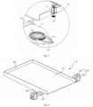
- Fig. 6 is a schematic view of the temporary-storage partition plate 4 according to an embodiment of the present invention.
- the temporary-storage partition plate 4 includes a partition plate body 41 arranged horizontally and a connection rod 42 arranged along the X direction; a lower surface of the partition plate body 41 is connected to the connection rod 42; and two ends of the connection rod 42 are detachably connected to two support columns 21.
- the partition plate body 41 By providing the partition plate body 41, it is convenient to temporarily store the cargo box 7, and by providing the connection rod 42, the overall structural strength and rigidity of the temporary-storage partition plate 4 can be improved.
- the connection rod 42 and the partition plate body 41 are connected by welding.
- the partition plate body 41 has a rectangular structure, and three sides of the partition plate body 41 are vertically surrounded by flanges 44.
- the flanges 44 protrude from an upper surface of the temporary-storage partition plate 4 to prevent the cargo box 7 on the partition plate body 41 from falling off the partition plate body 41.
- the flanges 44 on the three sides form a U-shaped opening facing a side where the rotation mechanism 5 is located, so as to prevent the flanges 44 from affecting the action of the cargo box conveying mechanism 1.
- connection rod 42 is connected to a side of the partition plate body 41 close to the rotation mechanism 5.
- a reinforcing rib plate 45 is connected between a lower surface of the partition plate body 41 and the connection rod 42.
- the position and number of the reinforcing rib plates 45 can also be determined according to actual use requirements and required structural strength and rigidity.
- the partition plate body 41 is integrally formed with the baffle portion and the reinforcing rib plates 45, which is convenient to be processed and reduces cost.
- connection rod 42 is detachably connected to the support column 21 through an adapter 43 provided at an end of the connection rod.
- the adapter 43 includes one first connection plate 431 and two second connection plates 432 and forms a U-shaped structure; the first connection plate 431 is detachably connected to an outer side surface of one of two reinforcement rods 212, the outer side surface being away from the other reinforcement rod 212; the two second connection plates 432 are parallel and spaced apart from each other; and each of the second connection plates 432 includes a hole for insertion of the connection rod 42, and the connection rod 42 is in interference fit with the hole.
- connection rod 42 and the adapter 43 can also be welded as one piece.
- the first connection plate 431 includes a first through hole, and the reinforcement rod 212 includes a first connecting threaded hole, correspondingly.
- the adapter 43 is connected by a threaded connector threaded into the first through hole and the first connecting threaded hole. Further, a height position of the temporary-storage partition plate 4 on the support column 21 is adjustable.
- the reinforcement rod 212 includes a plurality of first connecting threaded holes arranged at intervals along a height direction of the reinforcement rod, and the first through hole in the first connection plate 431 is selectively connected to one of the plurality of first connecting threaded holes, thereby adjusting a height position of connection between the first connection plate 431 and the reinforcement rod 212, that is, adjusting the height position of the temporary-storage partition plate 4 on the support column 21.
- the reinforcement rod 212 may be provided with a plurality of first connecting threaded holes evenly spaced over its entire length, so that the positions of the temporary-storage partition plates 4 in the entire height direction of the support column 21 can be adjusted, which widens an adjustment range.
- the number of temporary-storage partition plates 4 on the support column 21 and the height position of each temporary-storage partition plate 4 may be preset, and for each temporary-storage partition plate 4, a plurality of first connecting threaded holes are arranged at intervals along the height direction in a local area where the preset height position is located.
- the position of the temporary-storage partition plate 4 in the height direction is adjusted by arranging the plurality of spaced first connecting threaded holes on the support column 21 along the height direction, which is convenient to adjust and is arranged at intervals.
- the height position of the temporary-storage partition plate 4 on the support column 21 may be adjusted in other ways.
- the first connection plate 431 includes an elongated hole, and the elongated hole has a length consistent with the vertical direction and a width adapted to the first connecting threaded hole.
- other connection methods in the related art can be adopted to realize the height adjustment, which will not be elaborated herein.
- the structure of the temporary-storage partition plate 4 in this embodiment is merely exemplary, and this embodiment does not limit the specific structure of the temporary-storage partition plate 4, as long as it can support the cargo box 7 and realize the detachable connection with the door frame 2.
- the lifting mechanism 3 is used to drive the rotation mechanism 5 and the cargo box conveying mechanism 1 to rise and fall vertically, so as to transfer the cargo boxes 7 at different layers of the inventory container and/or the cargo boxes 7 on the temporary-storage partition plates 4 at different heights.
- the lifting mechanism 3 as a self-driven lifting mechanism includes a mounting seat 31, a lifting drive unit 32, and a lifting transmission assembly 33, the lifting drive unit 32 and the lifting transmission assembly 33 being on the mounting seat 31.
- the support column 21 includes an auxiliary transmission member 23.
- the lifting drive unit 32 drives the lifting transmission assembly 33 to transmissively cooperate with the auxiliary transmission member 23, to allow the mounting seat 31 to be vertically raised and lowered along the support column 21.
- the lifting drive unit 32 includes a lifting drive motor.
- the lifting transmission assembly 33 includes two first lifting synchronization wheels 331 spaced apart along the vertical direction, and a first lifting synchronous belt 332 wound around the two first lifting synchronization wheels 331, the first lifting synchronous belt 332 being a double-sided toothed synchronous belt.
- the lifting drive motor is connected to one of the two first lifting synchronization wheels 331.
- the auxiliary transmission member 23 is a synchronous belt rack meshing with the first lifting synchronous belt 332. As a result, the lifting drive motor drives one of the two first lifting synchronization wheels 331 to rotate and in turn brings the first lifting synchronous belt 332 into rotation.
- the synchronous belt rack Since the first lifting synchronous belt 332 meshes with the synchronous belt rack, the synchronous belt rack is fixed. The first lifting synchronous belt 332 rises or falls vertically along the synchronous belt rack when rotating, such that the entire lifting mechanism 3 rises or falls vertically along the height direction of the support column 21.
- each support column 21 is correspondingly provided with a synchronous belt rack to ensure the lifting stability of the lifting mechanism 3. Furthermore, the two groups of lifting transmission assemblies 33 are driven by one lifting drive motor to ensure the synchronization of the two groups of lifting transmission assemblies 33 and reduce the operating cost of the lifting mechanism 3.
- the mounting seat 31 includes a first mounting plate 311 arranged horizontally and two second mounting plates 312 vertically arranged at both ends of the first mounting plate 311.
- the lifting drive motor is arranged on the first mounting plate 311, the lifting transmission assemblies 33 are arranged on the second mounting plates 312.
- Such an arrangement has a simple structure and can reduce the overall weight of the lifting mechanism 3.
- the first mounting plate 311 is connected to respective upper ends of the second mounting plates 312. Consequently, a sufficient installation space for the lifting drive motor can be guaranteed, and the lifting mechanism 3 will not occupy the bottom space when moving to the bottom of the door frame 2, which can reduce the interference of the lifting mechanism 3 with the cargo box conveying mechanism 1 and the rotation mechanism 5.
- the two groups of lifting transmission assemblies 33 adopt the lifting synchronization transmission component 34 to realize synchronous transmission.
- the lifting synchronization transmission component 34 includes a lifting synchronization shaft 341 arranged along the X direction. Two ends of the lifting synchronization shaft 341 are rotatably supported on the first mounting plate 311 through a bearing seat and a bearing.
- a driven gear 345 is fitted over the lifting synchronization shaft 341; a driving gear is fitted over an output shaft of the lifting drive motor; and the driving gear meshes with the driven gear 345.
- a second lifting synchronization wheel 342 is fitted over each of the two ends of the lifting synchronization shaft 341.
- a side of the second mounting plate 312 away from the support column 21 is provided with a third lifting synchronization wheel 343 coaxially connected to one of the first lifting synchronization wheels 331.
- the second lifting synchronization wheels 342 and the third lifting synchronization wheel 343 are spaced apart from each other in the vertical direction, and a second lifting synchronous belt 344 is wound around the second lifting synchronization wheel 342 and the third lifting synchronization wheel 343.
- the lifting synchronization transmission assembly 34 by providing the driving gear and the driven gear 345, the lifting synchronization shaft 341 can be driven to rotate, and meanwhile, the lifting speed of the lifting mechanism 3 can be controlled by control over a transmission ratio of the driving gear and the driven gear 345, so as to achieves a purpose of slowing down the lifting.
- the lifting synchronization transmission assembly 34 in this embodiment is only an exemplary structure, and any structure of the lifting synchronization transmission assembly 34 that can realize the synchronous movement of the two groups of lifting transmission assemblies 33 in the related art can be employed in the present invention.
- the lifting drive motor, the lifting synchronization shaft 341, and the second lifting synchronization wheel 342 are all arranged above the first mounting plate 311, and each of two ends of the first mounting plate 311 is provided with an avoidance hole for the second lifting synchronous belt 344 to pass through.
- This arrangement improves the installation stability of the lifting mechanism 3 and avoids interference between the lifting mechanism 3 and the cargo box conveying mechanism 1.
- the lifting drive motor and the lifting synchronization shaft 341 may also be arranged on a lower surface of the second mounting plate 312.
- the auxiliary transmission member 23 is arranged on a side of one of the reinforcement rods 212 facing the other reinforcement rod 212 to improve the overall aesthetics of the door frame 2.
- the lifting transmission assembly 33 is arranged on a side of the second mounting plate 312 facing the main body plate 211, so that the lifting transmission assembly 33 is located in the U-shaped groove of the support column 21 and located between the bottom of the U-shaped groove and the second mounting plate 312, which can protect the lifting transmission assembly 33.
- the lifting mechanism 3 further includes a lifting guide assembly to guide the lifting.
- the lifting guide assembly includes a plurality of lifting guide wheels 35 arranged at intervals in the vertical direction.
- the lifting guide wheels 35 and the lifting transmission assembly 33 are located on the same side of the second mounting plate 312.
- the lifting guide wheels 35 and the second mounting plate 312 are rotatably connected, and the lifting guide wheels 35 abut against the reinforcement rod 212 on which no auxiliary transmission member 23 is provided.
- the lifting guide wheels 35 By arranging the lifting guide wheels 35, the lifting guide wheels 35 and the first lifting synchronous belt 332 are confined between the two reinforcement rods 212, which ensures that the first lifting synchronous belt 332 always meshes with the synchronous belt rack and avoids the rotation, falling and loosening of the lifting mechanism 3. Moreover, since the lifting guide wheels 35 are rotatably connected to the second mounting plate 312, resistance against the vertical lifting of the lifting mechanism 3 can be reduced while performing the guiding and limiting. Moreover, since there is no need for any additional structure on the support column 21 to be fitted with the lifting guide wheel 35, the structural complexity of the transfer robot can be simplified and the modular design of the support column 21 can be facilitated. In other embodiments, the lifting guide assembly may also be slidably connected to the reinforcement rod 212 on which no auxiliary transmission member 23 is arranged.
- a lifting travel of the lifting mechanism 3 is not limited by the height of a single support column 21, which is beneficial to the modular arrangement of the support column 21.
- the lifting transmission assembly 33 adopts a form of synchronous belt transmission
- the auxiliary transmission member 23 is in the form of the synchronous belt rack
- more teeth are meshing simultaneously when the first lifting synchronous belt 332 is fitted with the synchronous belt gear, the stability of connection between the lifting mechanism 3 and the support column 21 can be enhanced, and the lift mechanism 3 is prevented from falling off.
- the lifting transmission assembly 33 is configured as a gear transmission form
- the auxiliary transmission member 23 is configured as a rack fitted with the gear.
- the lifting mechanism 3 may also be a non-climbing lifting mechanism 3, such as a sprocket-chain transmission mechanism, a screw-nut transmission mechanism, and a linkage transmission mechanism.
- the support column 21 has a receiving groove 25 with an opening facing the other support column 21; the auxiliary transmission member 23 is arranged on a side groove wall of the receiving groove 25; and the lifting guide assembly is slidably or rollingly connected to the other opposite groove wall.
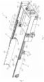
- Fig. 7 is a schematic view of the cargo box conveying mechanism according to an embodiment of the present invention.
- the cargo box conveying mechanism 1 includes: a transit plate 11, a telescopic assembly 12 and a box retrieval assembly 13.
- the transit plate 11 is used for temporary storage and transit of the cargo box 7 picked up by the cargo box conveying mechanism 1.
- the box retrieval assembly 13 is used to pick up the cargo box 7 on the temporary-storage partition plate 4 or the inventory container, so that the cargo box 7 is shifted between the transit plate 11 and the inventory container or between the temporary-storage partition plate 4 and the transit plate 11.
- the telescopic assembly 12 is connected to the transit plate 11 and the box retrieval assembly 13 and is used to drive the box retrieval assembly 13 to extend and retract horizontally relative to the transit plate 11.
- a group of telescopic assemblies 12 is arranged on each of two opposite sides of the transit plate 11.
- the telescopic assembly 12 is a two-stage synchronous telescopic structure, which helps to increase a maximum length of the telescopic assembly 12 during extension and reduce a size of the telescopic assembly 12 during retraction, such that the overall size of the transfer robot is reduced, and the extension or retraction efficiency of the box retrieval assembly 13 is improved.
- the telescopic assembly 12 includes a fixed plate 121, a connection plate 122, a telescopic plate 123, a telescopic transmission assembly 125, and a telescopic drive assembly 126.
- the fixed plate 121, the connection plate 122, and the telescopic plate 123 are arranged in parallel.
- the telescopic transmission assembly 125 and the telescopic drive assembly 126 drive the connection plate 122 and the telescopic plate 123 to extend or retract synchronously.
- the fixed plate 121 is perpendicularly connected to the transit plate 11.
- the telescopic assembly 12 may also be a three-stage synchronous telescopic structure.
- the telescopic transmission assembly 125 includes: a first telescopic transmission assembly configured to realize horizontal extension and retraction of the connection plate 122 relative to the fixed plate 121; and a second telescopic transmission assembly configured to realize horizontal extension and retraction of the telescopic plate 123 relative to the connection plate 122.
- the first telescopic transmission assembly includes: two first pulleys 1251 spaced apart from each other and arranged at both ends of the fixed plate 121; and a first synchronous belt 1252 wound around the two first pulleys 1251, centers of the two first pulleys 1251 being at a same height.
- the telescopic drive assembly 126 includes a telescopic drive motor having a horizontally arranged output shaft, and the output shaft of the telescopic drive assembly 126 is connected to one of the two first pulleys 1251.
- the second telescopic transmission assembly includes: two second pulleys 1253 arranged at both ends of the connection plate 122; and a second synchronous belt 1254 wound around the two second pulleys 1253, centers of the two second pulleys 1253 being at a same height.
- connection plate 122 is connected to the first synchronous belt 1252 through a first connector 1255; a second end of the fixed plate 121 is connected to the second synchronous belt 1254 through a second connector 1258; and a first end of the telescopic plate 123 is connected to the second synchronous belt 1254 through a third connector.
- a first end of the fixed plate 121, the first end of the connection plate 122 and the first end of the telescopic plate 123 are arranged correspondingly, and the first connector 1255 and the third connector are both located at the first end of the fixed plate 121; when the telescopic assembly 12 is in a maximum extension state, the first connector 1255 and the second connector 1258 are both located at the second end of the fixed plate 121, and the third connector is located at a second end of the connection plate 122.
- a group of telescopic assemblies 12 is arranged at each of the two opposite sides of the transit plate 11.
- the telescopic assembly 12 also includes a telescopic synchronization transmission assembly 127.
- the telescopic synchronization transmission assembly 127 includes a third pulley 1272 fitted over the output shaft of the telescopic drive motor, a telescopic synchronization shaft 1271, a fourth pulley 1273 fitted over the telescopic synchronization shaft 1271, and a third synchronous belt 1274 wound around the fourth pulley 1273 and the third pulley 1272, in which each of both ends of the telescopic synchronization shaft 1271 passes through one first pulley 1251 of each of two telescopic assemblies 12; and the fourth pulley 1273 and the third pulley 1272 are spaced apart in the vertical direction.
- the telescopic assembly 12 further includes a telescopic guide assembly 128.
- the telescopic guide assembly 128 includes a first guide groove 1281 on an inner side of the fixed plate 121; a second guide groove 1282 on an inner side of the connection plate 122; a first guide rail 1283 on an outer side of the connection plate 122 and slidably fitted with the first guide groove 1281; and a second guide rail 1284 on an inner side of the telescopic plate 123 and slidably fitted with the second guide groove 1282.
- the present invention is not limited to the above-mentioned structure of the telescopic guide assembly 128, and any structure capable of realizing the telescopic guide from the related art can be applied to the present invention.
- the telescopic assembly 12 in this embodiment is a unidirectional telescopic structure, which can reduce the installation cost of the telescopic assembly 12, and adopts a transmission form of the synchronous belt, which has a simple structure, convenient installation, and low cost.
- the structure of the telescopic assembly 12 in this embodiment is only an exemplary structure, and the telescopic assembly 12 is not limited to the above structure.
- the telescopic assembly 12 can also adopt an existing structure that can realize two-stage synchronous extension and retraction.
- the first telescopic transmission assembly may employ rack-pinion transmission, chain-sprocket transmission, and etc.
- the telescopic assembly 12 may also adopt an existing structure that can realize two-stage extension and retraction, which will not be elaborated herein.
- the telescopic drive assembly 126 and the telescopic synchronization transmission assembly 127 are both arranged above the transit plate 11.
- a partition plate 15 is arranged on a side of the transit plate 11 where a cargo box entry-exit port is located; a lower surface of the partition plate 15 is perpendicularly connected to the transit plate 11; two ends of the partition plate 15 are detachably connected to two fixed plates 121 correspondingly; and the telescopic drive assembly 126 and the telescopic synchronization transmission assembly 127 are arranged on a side of the partition plate 15 away from the cargo box entry-exit port.
- the transit plate 11, the fixed plates 121 on the two opposite sides of the transit plate 11, and the partition plate 15 form a temporary storage area for accommodating the cargo box 7.
- the transit plate 11 is provided with baffles 14 on the two opposite sides corresponding to the telescopic assemblies 12, and the baffles 14 are located inside the telescopic assembly 12 and extend along a telescopic direction of the telescopic assembly 12.
- a distance between two baffles 14 is slightly larger than a width of the cargo box 7, so that the cargo box 7 can be accommodated between the two baffles 14, and the baffles 14 can prevent the cargo box 7 from colliding with the telescopic assemblies 12.
- the baffle 14 includes a baffle main body 141 and a guide plate 142 at each of both ends of the baffle main body 141.
- the guide plate 142 has a first end connected to the baffle main body 141, and a second end extending obliquely in a direction away from the baffle main body 141 towards a direction close to the fixed plate 121, so that two baffle main bodies 141 at a same end of the transit plate 11 exhibit an outwardly flared structure, to guide the cargo box 7 into the temporary storage area.
- the transit plate 11 includes a guide portion 112 at the cargo box entry-exit port; and the guide portion 112 has a first end connected to a transit plate body 111 and a second end obliquely extending downward in a direction away from the transit plate body 111, to further guide the shift of the cargo box 7 onto the transit plate 11.
- an edge-folding portion 113 is arranged at each of two sides of the transit plate which are provided with the telescopic assemblies 12.
- the edge-folding portion 113 is perpendicularly connected to the transit plate body 111, and the fixed plate 121 of the telescopic assembly 12 is detachably connected to the edge-folding portion 113.
- the box retrieval assembly 13 is arranged at an end of the telescopic plate 123.
- the box retrieval assembly 13 is a toggle lever type box retrieval assembly, which includes a toggle lever 131 and a toggle lever driving member 132.
- a fixed end of the toggle lever driving member 132 is fixed to the telescopic plate 123, and a driving end of the toggle lever driving member 132 is connected to the toggle lever 131, to drive the toggle lever 131 to switch between a working position where the cargo box 7 can be toggled and an idle position where the cargo box 7 cannot be toggled.
- the toggle lever driving member 132 is a drive motor, an output shaft of the drive motor is consistent with a length direction of the telescopic plate 123, and the output shaft of the drive motor is connected to a first end of the toggle lever 131 to drive the toggle lever 131 to rotate in a vertical plane.
- toggle lever 131 when the toggle lever 131 is in the working position, a second end of the toggle lever 131 extends into between the two telescopic plates 123, and the toggle lever 131 is perpendicular to the telescopic plate 123.
- the toggle lever 131 When the toggle lever 131 is in the idle position, the toggle lever 131 is vertically arranged to avoid collision with other structures when the toggle lever 131 is not working.
- the present invention is not limited thereto, and the working position and the idle position of the toggle lever 131 can be set according to requirements.
- the toggle lever 131 can not only be rotated in the vertical plane, but also can be rotated in a horizontal plane to switch between the working position and the idle position.
- the toggle lever driving member 132 is a steering engine, such that a rotation angle of the toggle lever 131 can be precisely controlled through a feedback mechanism and an angle setting of the steering engine, and the steering engine has a small volume, which is beneficial to the installation and arrangement of the toggle lever driving member 132.
- the drive motor may also be a servo motor and other driving forms capable of controlling the rotation angle.
- the box retrieval assembly 13 is arranged at each of two ends of the telescopic plate 123 along the length direction of the telescopic plate 123.
- two groups of box retrieval assemblies 13 on the same telescopic plate 123 are located on two opposite sides of the cargo box 7 correspondingly, to better realize the movement of the cargo box 7 between the temporary storage area and the inventory container, and achieve the transportation of the cargo box 7 on the inventory containers on two opposite sides of the transfer robot.
- the box retrieval assembly 13 close to an end of the partition plate 15 only includes the toggle lever 131, and the toggle lever 131 is always perpendicularly connected to the telescopic plate 123, so that the number of the toggle lever driving members 132 can be reduced, and the overall cost and control complexity of the transfer robot can be reduced.
- one toggle lever 131 is arranged at an end of each telescopic plate 123.
- the end of the telescopic plate 123 may also be provided with two or more toggle levers 131 at intervals along the height direction.
- the box retrieval assembly 13 adopting the toggle lever 131 can toggle the cargo box 7 by switching a state of the toggle lever 131, which imposes no additional restriction and requirement on the shape and size of the cargo box 7, and has good versatility. Moreover, since the telescopic plates 123 extend to both sides of the cargo box 7 to toggle the cargo box 7, the cargo box 7 can be picked and placed stably and is easy to operate. In other embodiments, other types of box retrieval assemblies 13 in the related art can also be used to pick and place the cargo box 7, such as a clamp-type telescopic fork, and a lift-type telescopic fork. When the clamp-type telescopic fork or the lift-type telescopic fork is used, the transit plate 11 may not perform a function of transferring the cargo box 7 but only serves as a connection support structure for the telescopic assembly 12.
- Fig. 5 is a partially enlarged view of part J in Fig. 3 .
- the cargo box conveying mechanism 1 is connected to the lifting mechanism 3 through the rotation mechanism 5 to realize rotation of the cargo box conveying mechanism 1 around a vertical axis.
- the rotation mechanism 5 includes a support plate 53 for connection with the lifting mechanism 3; a rotation transmission assembly 52 arranged between the support plate 53 and a bottom of the cargo box conveying mechanism 1; and a rotation drive unit 51 for driving the rotation transmission assembly 52 to act.
- the rotation drive unit 51 includes a rotation drive motor having a vertically arranged drive shaft.
- a housing of the rotation drive unit is connected to an outer side surface of the fixed plate 121 through the mounting seat 31, which facilitates the disassembly and assembly of the drive motor.
- the rotation drive motor may also be connected to the partition plate 15 or the fixed plate 121.
- the rotation drive motor is a servo motor, which is beneficial to the precision control over the rotation angle.
- the rotation transmission assembly 52 is arranged between a mounting bottom plate and the support plate 53.
- the rotation transmission assembly 52 includes a rotation bearing 521, a rotation synchronization wheel 523, and a rotation synchronous belt 522.
- An inner ring end face of the rotation bearing 521 is connected to the mounting bottom seat, and an outer ring of the rotation bearing 521 is connected to the support plate 53.
- the rotation synchronous belt 522 is a single-sided toothed synchronous belt having inner transmission teeth.
- a peripheral surface of the outer ring of the rotation bearing 521 is provided with a gear ring 5211 meshing with the rotation synchronous belt 522.
- the rotation synchronization wheel 523 is fitted over the drive shaft of the rotation drive motor.
- the rotation synchronous belt 522 is wound around the gear ring 5211 and the rotation synchronization wheel 523. With this arrangement, when the drive shaft of the rotation drive motor rotates, the rotation synchronous belt 522 is driven to rotate relative to the gear ring 5211. Since the ring gear 5211 is fixed relative to the support plate 53, the rotation synchronous belt 522 rotates horizontally around a center of the ring gear 5211, and hence the rotation drive motor and the cargo box conveying mechanism 1 connected to the rotation drive motor are driven to rotate horizontally.
- a bottom surface of the mounting bottom plate is provided with a limiting slot that matches a shape of the rotation synchronous belt 522, and the rotation synchronous belt 522 is snapped in the limiting slot.
- the bottom of the cargo box conveying mechanism 1 is provided with an accommodating groove 25 that matches the shape of the rotation synchronous belt 522, and the rotation synchronous belt 522 is arranged in the accommodating groove 25.
- connection portion 531 is vertically arranged at a position of the support plate 53 corresponding to each of the two second mounting plates 312.
- the connection portion 531 has an L-shaped structure with a first side connected to the support plate 53 and a second side perpendicular to the support plate 53. Two opposite sides of the second mounting plate 312 abut against two sides of the connection portion 531 correspondingly, and the second mounting plate 312 is threadedly connected to the second side of the connection portion 531 perpendicular to the support plate 53.
- the structural arrangement of the connection portion 531 can position and limit the connection between the support plate 53 and the second mounting plate 531.
- the above structure of the rotation transmission assembly 52 is only an exemplary structure, and the present invention does not limit the structure of the rotation transmission assembly 52, as long as the structural form of the rotation transmission assembly 52 can realize the rotation of the cargo box conveying mechanism 1 around the vertical axis relative to the support plate 53, which will fall into the protection scope of the present invention.
- the transfer robot further includes a control system for controlling operation of various actions of the transfer robot.
- the control system includes a controller, an order management module, a navigation module for realizing an autonomous navigation function of the movable chassis 6, an information transmission module, an information processing module, an identification module, a display module, an alarm module, and a power supply module.
- the drive wheel mechanism, the lifting drive unit 32, the telescopic drive assembly 126, the toggle lever driving member 132, the detection assembly, and various modules in the control system are all connected to the controller.
- the arrangement of the control system and the operation and control over the transfer robot are conventional in the art, and will not be elaborated in this embodiment.
- This embodiment also provides a warehouse logistics system that includes the aforementioned transfer robot.
- the transfer robot in this embodiment also includes a movable chassis 6, a door frame 2 arranged on the movable chassis 6, at least two cargo box conveying mechanisms 1 along a height direction of the door frame 2, and a lifting mechanism 3 that drives the box conveying mechanisms 1 to vertically rise or fall relative to the door frame 2.
- Each cargo box conveying mechanism 1 includes a telescopic assembly 12, a transit plate 11, and a box retrieval assembly 13.
- the difference between the first and second embodiments lies in that the structure of the telescopic assembly 12 in this embodiment is different from that in the first embodiment. Only the structure of the telescopic assembly 12 is elaborated in this embodiment, and the same structures as the first embodiment will not be repeated.
- Fig. 8 is a schematic view of the cargo box conveying mechanism according to the second embodiment of the present invention.
- the telescopic assembly 12 is a three-stage synchronous telescopic structure, which can increase an extension length of the telescopic plate 123, and realize the pick-up of an inner cargo box 7 in a deep double-location inventory container.
- the deep double-location inventory container means that the inventory container includes two storage locations arranged side by side in the telescopic direction of the telescopic assembly 12 along a depth direction.
- each inventory container in order to improve the space utilization rate of the warehouse, usually has an inventory container immediately adjacent to its first side and another inventory container spaced apart from its second side, and an aisle exists between the two inventory containers spaced apart from each other and allows the transfer robot to pass through.
- the cargo box 7 in an inside storage location can be toggled by the box retrieval assembly 13 only when an extension plate of the telescopic assembly 12 to pass over an outside storage location. Consequently, a maximum extension length of the telescopic assembly 12 needs to be increased, in order to pick up the cargo box 7 in the inside storage location.
- the telescopic assembly 12 includes a fixed plate 121, a connection plate 122, an extension plate 124, and a telescopic plate 123 sequentially arranged from the outside to the inside.
- the telescopic assembly 12 also includes a telescopic transmission assembly 125 and a telescopic drive assembly 126 for realizing synchronous extension and retraction of the connection plate 122, the fixed plate 121, and the telescopic plate 123.
- the telescopic drive assembly 126 includes a drive motor.
- the telescopic transmission assembly 125 includes a first telescopic transmission assembly configured to realize horizontal extension and retraction of the connection plate 122 relative to the fixed plate 121; a second telescopic transmission assembly configured to realize horizontal extension and retraction of the extension plate 124 relative to the connection plate 122; and a third telescopic transmission assembly configured to realize horizontal extension and retraction of the telescopic plate 123 relative to the extension plate 124.
- the first telescopic transmission assembly includes: two first pulleys 1251 arranged at both ends of the fixed plate 121 in a length direction of the fixed plate; and a first synchronous belt 1252 wound around the two first pulleys 1251. Central axes of the two first pulleys 1251 are at a same height. One of the two first pulleys 1251 is connected to an output shaft of the drive motor. A first end of the connection plate 122 is detachably connected to the first synchronous belt 1252 through a first connector 1255.
- connection plate 122 acts along with the first synchronous belt 1252, realizing the horizontal extension and retraction of the connection plate 122 relative to the fixed plate 121.
- the second telescopic transmission assembly includes: two second pulleys 1253 arranged at both ends of the telescopic plate 123; and a second synchronous belt 1254 wound around the two second pulleys 1253. Centers of the two second pulleys 1253 are at a same height.
- the second synchronous belt 1254 is connected to the extension plate 124 through a second connector 1258 and is connected to a second end of the fixed plate 121 through a third connector.
- the third telescopic transmission assembly includes: two fifth pulleys 1256 arranged at both ends of the extension plate 124 in a length direction of the extension plate; and a fourth synchronous belt 1257 wound around the fifth pulleys 1256. Centers of the two fifth pulleys 1256 are at a same height.
- the telescopic plate 123 is connected to the fourth synchronous belt 1257 through a fourth connector, and a second end of the connection plate 122 is connected to the fourth synchronous belt 1257 through a fifth connector.
- Such a transmission structure with three synchronous belts can realize the horizontal extension and retraction of the connection plate 122, the extension plate 124, and the telescopic plate 123.
- the structure is simple, and the cost is low.
- the telescopic assembly 12 is in a retraction state (i.e., an initial state)
- the first connector 1255, the second connector 1258, and the fourth connector are all located near a first end of the fixed plate 121;
- the third connector and the fifth connector are located near the second end of the fixed plate 121; and respective first ends of the fixed plate 121, the connection plate 122, the extension plate 124, and the telescopic plate 123 are arranged correspondingly.
- the first connector 1255 is located near the second end of the fixed plate 121; the second connector 1258 is located near the second end of the connection plate 122; the third connector is located near the second end of the fixed plate 121; the fourth connector is located near a second end of the extension plate 124; and the fifth connector is located near the second end of the connection plate 122. That is, a telescopic travel of the connection plate 122, the extension plate 124, and the telescopic plate 123 is smaller than a distance between the pulleys at both ends of the connected synchronous belt.
- the telescopic assembly 12 has a simple structure and is convenient to install, and can realize bidirectional extension and retraction of the telescopic assembly 12, so as to realize synchronous pick-up of the cargo boxes 7 in the inventory containers on two opposite sides of the transfer robot. It can be understood that the present invention is not limited to the use of the above-mentioned telescopic assembly 12 to achieve the three-stage extension and retraction. In other embodiments, other three-stage synchronous telescopic structures from the related art can also be used to implement the synchronous extension and retraction of the extension plate 124, the connection plate 122, and the telescopic plate 123. Alternatively, a structure in which the connection plate 122, the extension portion and the telescopic plate 123 extend or retract in a staged manner can be adopted to realize the maximum extension of the telescopic plate 123.
- a total length of the telescopic assembly 12 is greater than a sum of lengths of three cargo boxes 7, so that the telescopic plate 123 can pass over a front storage location to pick up the cargo box 7 in a rear storage location of the deep double-location inventory container.
- the telescopic assembly 12 is arranged at each of two opposite sides of the transit plate 11; the two telescopic assemblies 12 are synchronously driven by the same telescopic drive assembly 126; and the telescopic drive assembly 126 drives the first pulleys 1251 of the two telescopic assemblies 12 through the telescopic synchronization transmission assembly 127.
- the structures of the telescopic drive assembly 126 and the telescopic synchronization transmission assembly 127 as well as their arrangement on the transit plate 11 may refer to the first embodiment and will not be elaborated in this embodiment.
- this embodiment is not limited to the above-mentioned structural form of the synchronization transmission assembly, and other structural forms that can realize the synchronous rotation of the two first pulleys 1251 can also be used, which will not be illustrated in detail.
- the transfer robot in this embodiment is not only suitable for picking and placing the cargo boxes 7 in the deep double-location inventory containers, but also suitable for picking and placing deep three-location or deep four-location inventory containers. Moreover, for the deep double-location inventory containers and the deep four-location inventory containers, when placed in a warehouse, every two adjacent inventory containers are spaced apart to form an aisle between the two inventory containers to allow the transfer robot to pass through.
- This embodiment also provides a warehouse logistics system that includes the aforementioned transfer robot.
- Fig. 9 is a flowchart of a box retrieval method according to a third embodiment of the present invention.
- the box retrieval method according to this embodiment picks up a target cargo box on an inventory container by using the transfer robot according to the first or second embodiment, so as to realize a sorting task.
- Picking up each target cargo box includes:
- the box retrieval method uses the transfer robot in the first or second embodiment to perform a box retrieval operation on the cargo box 7, so that the height of the cargo box 7 that can be picked up is not limited to the height of the temporary-storage partition plate 4, which improves the applicability and versatility of the box retrieval method.
- the transfer robot can transfer a plurality of cargo boxes 7 simultaneously, which improves the transfer efficiency and hence the efficiency of warehouse logistics.
- Fig. 10 is a flowchart of a cargo box loading method according to a fourth embodiment of the present invention.
- this embodiment provides a cargo box loading method based on a transfer robot, to load a cargo box 7 to a target position of an inventory container, which improves the efficiency of loading the cargo box 7 or returning the cargo box after sorting by the transfer robot.
- the cargo box loading method according to this embodiment is applicable to the transfer robot in the first embodiment or the second embodiment.
- the loading of the cargo box 7 may be a return operation of returning the cargo box 7 to the storage location in the inventory container after a sorting operation of picking up the cargo box 7 from the inventory container, or may be a loading operation of replenishing a new cargo box 7 into the inventory container, or may be an operation of placing the cargo box 7 into the inventory container for other reasons, which will not be specifically limited in this embodiment.
- the box returning method in this embodiment includes:
- the operation of placing the cargo box 7 in the target position by the cargo box conveying mechanism 1 includes:
- the step S4033 specifically includes:
- the step S4037 specifically includes:
- the cargo box loading method in this embodiment uses the transfer robot in the first or second embodiment to carry out an loading operation of the cargo box 7, so that the height of the cargo box 7 is not limited to the height of the temporary-storage partition plate 4, which improves the applicability and versatility of the box retrieval method. Moreover, the transfer robot can transfer a plurality of cargo boxes 7 simultaneously, which improves the transfer efficiency and hence the efficiency of warehouse logistics.
Landscapes
- Engineering & Computer Science (AREA)
- Mechanical Engineering (AREA)
- Robotics (AREA)
- Warehouses Or Storage Devices (AREA)
- Manipulator (AREA)
Applications Claiming Priority (2)
| Application Number | Priority Date | Filing Date | Title |
|---|---|---|---|
| CN202010524246.4A CN111703799A (zh) | 2020-06-10 | 2020-06-10 | 一种搬运机器人、取箱方法、货箱上货方法及仓储物流系统 |
| PCT/CN2021/095276 WO2021249163A1 (zh) | 2020-06-10 | 2021-05-21 | 搬运机器人、取箱方法、货箱上货方法及仓储物流系统 |
Publications (3)
| Publication Number | Publication Date |
|---|---|
| EP4166476A1 true EP4166476A1 (de) | 2023-04-19 |
| EP4166476A4 EP4166476A4 (de) | 2024-02-28 |
| EP4166476B1 EP4166476B1 (de) | 2025-08-27 |
Family
ID=72539651
Family Applications (1)
| Application Number | Title | Priority Date | Filing Date |
|---|---|---|---|
| EP21821379.1A Active EP4166476B1 (de) | 2020-06-10 | 2021-05-21 | Transferroboter |
Country Status (8)
| Country | Link |
|---|---|
| US (2) | US12479663B2 (de) |
| EP (1) | EP4166476B1 (de) |
| JP (1) | JP7470208B2 (de) |
| KR (1) | KR102861405B1 (de) |
| CN (1) | CN111703799A (de) |
| AU (1) | AU2021289874B2 (de) |
| DE (1) | DE202021004543U1 (de) |
| WO (1) | WO2021249163A1 (de) |
Cited By (1)
| Publication number | Priority date | Publication date | Assignee | Title |
|---|---|---|---|---|
| CN117284798A (zh) * | 2023-10-13 | 2023-12-26 | 安徽聚力粮机科技股份有限公司 | 智能入仓机器人 |
Families Citing this family (50)
| Publication number | Priority date | Publication date | Assignee | Title |
|---|---|---|---|---|
| CN111703799A (zh) * | 2020-06-10 | 2020-09-25 | 北京极智嘉科技有限公司 | 一种搬运机器人、取箱方法、货箱上货方法及仓储物流系统 |
| CN112371516B (zh) * | 2020-10-13 | 2022-04-05 | 海南科技职业大学 | 一种具有自动拣货功能的电商播种墙 |
| CN114379969B (zh) * | 2020-10-16 | 2023-06-27 | 北京极智嘉科技股份有限公司 | 库存容器操作系统和方法 |
| CN114455515A (zh) * | 2020-11-10 | 2022-05-10 | 上海擎日智能技术有限公司 | 一种用于货架盒的自动上下取放机 |
| CN114516506B (zh) * | 2020-11-20 | 2026-02-27 | 深圳市海柔创新科技有限公司 | 货物整理方法、设备、仓储系统及存储介质 |
| WO2022142242A1 (zh) * | 2020-12-30 | 2022-07-07 | 深圳市海柔创新科技有限公司 | 货叉组件及搬运机器人 |
| DE202022002857U1 (de) * | 2021-01-21 | 2023-10-11 | Beijing Geekplus Technology Co., Ltd. | System zur Handhabung von Frachtkisten |
| JP7533268B2 (ja) * | 2021-02-16 | 2024-08-14 | トヨタ自動車株式会社 | 搬送システム及び搬送方法 |
| CN113649777B (zh) * | 2021-07-15 | 2023-08-15 | 江苏兴达智能制造有限公司 | 一种800工字轮自动更换系统 |
| CN215477508U (zh) * | 2021-07-30 | 2022-01-11 | 深圳市海柔创新科技有限公司 | 搬运机器人及物流系统 |
| CN113716493B (zh) * | 2021-09-30 | 2025-05-06 | 腾米机器人科技(深圳)有限责任公司 | 一种搬运机器人及其搬运方法 |
| CN114194708B (zh) * | 2021-12-17 | 2023-11-24 | 芜湖市爱德运输机械有限公司 | 一种具备顶部双向输送功能的提升机 |
| CN114194683A (zh) * | 2021-12-19 | 2022-03-18 | 昆船智能技术股份有限公司 | 一种货物柔性补货和分拣的方法、系统及模组 |
| CN114291391B (zh) * | 2021-12-21 | 2023-12-29 | 浙江博秦精密工业有限公司 | 一种小型加工件转运输送装置 |
| CN114370733B (zh) * | 2022-01-11 | 2023-12-08 | 迪瑞医疗科技股份有限公司 | 一种带自动开关门功能的制冷装置及驱动控制方法 |
| CN114873413B (zh) * | 2022-01-24 | 2023-06-27 | 湘潭大学 | 施工升降机外笼底座 |
| CN114367453B (zh) * | 2022-01-26 | 2024-04-05 | 山东海奥斯生物科技股份有限公司 | 肠衣卷自动分级装置 |
| WO2023143406A1 (zh) * | 2022-01-29 | 2023-08-03 | 北京极智嘉科技股份有限公司 | 搬运机器人和具有其的仓储系统 |
| CN114408006B (zh) * | 2022-02-09 | 2022-11-22 | 山东商务职业学院 | 建筑工程用板材搬运装置 |
| CN114701764B (zh) * | 2022-03-10 | 2023-06-09 | 南通牧野机械有限公司 | 一种海绵存储仓 |
| CN114572619B (zh) * | 2022-03-29 | 2024-02-13 | 浙江金马逊智能制造股份有限公司 | 集箱长管弯管接头的全自动缓存上下料装置 |
| CN217375879U (zh) * | 2022-05-25 | 2022-09-06 | 深圳市海柔创新科技有限公司 | 挂装仓储系统 |
| US12552602B1 (en) * | 2022-06-14 | 2026-02-17 | Amazon Technologies, Inc. | Inventory system with item retrieval |
| WO2023245672A1 (zh) * | 2022-06-24 | 2023-12-28 | 深圳市海柔创新科技有限公司 | 爬货架机器人及仓储系统 |
| CN115213864B (zh) * | 2022-07-10 | 2024-11-01 | 广州盈福精密科技有限公司 | 一种便于调节的数控机床用工作台 |
| CN115043193B (zh) * | 2022-07-22 | 2024-04-05 | 广州城市理工学院 | 一种推倒运送机器人 |
| CN115303698B (zh) * | 2022-08-08 | 2025-02-28 | 迅得机械(东莞)有限公司 | 一种具有板件转向输送功能的暂存设备及暂存方法 |
| CN118025706A (zh) * | 2022-11-08 | 2024-05-14 | 深圳市海柔创新科技有限公司 | 分拣控制方法、管理设备、货架单元及仓储分拣系统 |
| WO2024101913A1 (ko) * | 2022-11-09 | 2024-05-16 | 주식회사 나우로보틱스 | 물류 로봇 |
| KR102614292B1 (ko) * | 2022-11-09 | 2023-12-15 | 주식회사 나우로보틱스 | 비규격 화물의 수용을 위한 물류 로봇 |
| CN115520416A (zh) * | 2022-11-09 | 2022-12-27 | 苏州鸿昱莱机电科技有限公司 | 一种三轴加料装钵机及其操作方法 |
| KR102614295B1 (ko) * | 2022-11-09 | 2023-12-15 | 주식회사 나우로보틱스 | 픽업 장치의 안정적 회전을 위한 물류 로봇 |
| KR102612190B1 (ko) * | 2022-11-28 | 2023-12-11 | 주식회사 나우로보틱스 | 재킹 타입 및 피킹 타입 호환 로봇용 적재유닛과 물류로봇시스템 |
| CN115628960B (zh) * | 2022-12-23 | 2023-03-28 | 中科百测(天津)检测技术有限公司 | 一种连续性高的物理吸附仪 |
| CN116331711B (zh) * | 2023-03-13 | 2023-09-12 | 广州联欣信息科技有限公司 | 一种库存补货管理装置以及管理方法 |
| TWI880187B (zh) * | 2023-03-24 | 2025-04-11 | 萬潤科技股份有限公司 | 搬送裝置、搬送設備及搬送系統 |
| CN116277078B (zh) * | 2023-05-24 | 2023-07-25 | 鸿誉展(广东)智能科技有限公司 | 一种基于传感器的工业机器人 |
| JP7838523B2 (ja) * | 2023-06-07 | 2026-04-01 | トヨタ自動車株式会社 | 管理装置、管理方法、管理プログラム及び集配システム |
| CN116812404A (zh) * | 2023-06-30 | 2023-09-29 | 广东安达智能装备股份有限公司 | 智能仓储物料转移系统 |
| CN116572279B (zh) | 2023-07-13 | 2023-09-26 | 驰逸自动化科技(苏州)有限公司 | 一种物料拣选机器人 |
| CN116901046B (zh) * | 2023-09-13 | 2023-12-08 | 宁波晶昭科技有限公司 | 光伏组件配置用机械手、光伏组件安装方法以及维护方法 |
| CN117416891B (zh) * | 2023-11-10 | 2024-07-02 | 中建二局第二建筑工程有限公司 | 一种用于厂房的立体货物运输平台 |
| JP2025086070A (ja) * | 2023-11-27 | 2025-06-06 | Thk株式会社 | ロボット |
| CN117533691B (zh) * | 2023-12-19 | 2024-06-25 | 青岛雅凯汽车工贸有限公司 | 一种冷藏车冷链货物进出装置及方法 |
| KR20250119822A (ko) | 2024-02-01 | 2025-08-08 | (주)디엠테크놀러지 | 박스 그리퍼 |
| KR102703352B1 (ko) * | 2024-04-08 | 2024-09-05 | 주식회사 에이아이로보틱스 | 보기 타입 서스펜션 장치를 구비하는 자율이동 로봇 |
| CN118372733B (zh) * | 2024-06-24 | 2024-08-27 | 河南工学院 | 一种直升机应急抢修车 |
| CN119262894B (zh) * | 2024-11-05 | 2026-04-28 | 中国科学院沈阳自动化研究所 | 一种大型无人直升机甲板仓储转运系统 |
| CN119928703A (zh) * | 2025-03-14 | 2025-05-06 | 湖南艾博特机器人技术有限公司 | 一种分体式仓储搬运机器人 |
| CN120423196B (zh) * | 2025-06-05 | 2025-11-28 | 湖南顺开科技有限公司 | 一种适用于车间生产包装线的储存输送工装架 |
Family Cites Families (29)
| Publication number | Priority date | Publication date | Assignee | Title |
|---|---|---|---|---|
| US4492504A (en) * | 1981-12-07 | 1985-01-08 | Bell & Howell Company | Materials handling system |
| ITMO20020076A1 (it) * | 2002-03-29 | 2003-09-29 | Ronflette Sa | Magazzino automatico |
| US20150125249A1 (en) | 2013-11-05 | 2015-05-07 | United Sortation Solutions, Inc. | Integrated stacking device and conveyor |
| EP3307652A4 (de) * | 2015-06-09 | 2019-03-13 | Commonsense Robotics Ltd. | Robotische inventurhandhabung |
| FR3042182B1 (fr) * | 2015-10-13 | 2020-09-18 | Exotec Solutions | Systeme de preparation de commandes |
| US10683171B2 (en) | 2016-09-30 | 2020-06-16 | Staples, Inc. | Hybrid modular storage fetching system |
| SG11201906596SA (en) * | 2017-01-16 | 2019-08-27 | Zhejiang Guozi Robotics Co Ltd | Robot for carrying container |
| CN108363389A (zh) | 2017-01-16 | 2018-08-03 | 浙江国自机器人技术有限公司 | 一种应用于移动机器人的超声波避障系统 |
| US11396424B2 (en) * | 2017-11-14 | 2022-07-26 | Hai Robotics Co., Ltd. | Handling robot |
| US11465840B2 (en) * | 2017-11-14 | 2022-10-11 | Hai Robotics Co., Ltd. | Handling robot |
| CN107840059B (zh) | 2017-11-30 | 2023-11-28 | 上海诺力智能科技有限公司 | 一种双向仓储自动取料机 |
| CN208008400U (zh) | 2017-12-22 | 2018-10-26 | 上海顶欣机电设备有限公司 | 一种基于agv小车平台上的货架式移动机器人 |
| CN108006162A (zh) * | 2017-12-25 | 2018-05-08 | 广州城建职业学院 | 环形双面齿高速小型化驱动直线运动模组 |
| CN209160601U (zh) * | 2018-09-07 | 2019-07-26 | 深圳市海柔创新科技有限公司 | 一种搬运机器人 |
| CN110194341B (zh) * | 2018-12-27 | 2024-06-25 | 北京极智嘉科技股份有限公司 | 一种搬运机器人及仓储系统 |
| CN209480472U (zh) * | 2019-01-29 | 2019-10-11 | 北京极智嘉科技有限公司 | 一种搬运机器人及仓储物流系统 |
| CN111620024B (zh) * | 2019-01-29 | 2023-08-25 | 北京极智嘉科技股份有限公司 | 一种搬运机器人、取货箱方法及放货箱方法 |
| US11542135B2 (en) * | 2019-02-01 | 2023-01-03 | Hai Robotics Co., Ltd. | Handling robot |
| CN209758195U (zh) * | 2019-02-01 | 2019-12-10 | 深圳市海柔创新科技有限公司 | 一种搬运机器人 |
| WO2021037229A1 (zh) * | 2019-08-30 | 2021-03-04 | 深圳市海柔创新科技有限公司 | 分拣机器人及分拣方法 |
| CN110422540B (zh) * | 2019-09-10 | 2020-11-03 | 浙江国自机器人技术有限公司 | 一种自动引导运输车和一种仓储系统 |
| KR102663107B1 (ko) * | 2019-09-30 | 2024-05-08 | 하이 로보틱스 씨오., 엘티디. | 운반 로봇, 화물 픽업 방법 및 지능형 창고 저장 시스템 |
| CN110626991B (zh) | 2019-10-23 | 2024-07-02 | 上海快仓智能科技有限公司 | 夹抱式伸缩装置和具有其的搬运机器人 |
| CN110775501B (zh) * | 2019-11-01 | 2021-03-12 | 山东科技大学 | 一种agv、自动化仓储装置及工作方法 |
| CN111605958A (zh) | 2020-06-10 | 2020-09-01 | 北京极智嘉科技有限公司 | 一种搬运机器人及仓储物流系统 |
| CN212952423U (zh) * | 2020-06-10 | 2021-04-13 | 北京极智嘉科技有限公司 | 一种搬运机器人及仓储物流系统 |
| CN212952422U (zh) * | 2020-06-10 | 2021-04-13 | 北京极智嘉科技有限公司 | 一种搬运机器人及仓储物流系统 |
| CN111703799A (zh) | 2020-06-10 | 2020-09-25 | 北京极智嘉科技有限公司 | 一种搬运机器人、取箱方法、货箱上货方法及仓储物流系统 |
| CN212923034U (zh) | 2020-06-10 | 2021-04-09 | 北京极智嘉科技有限公司 | 一种搬运机器人及仓储物流系统 |
-
2020
- 2020-06-10 CN CN202010524246.4A patent/CN111703799A/zh active Pending
-
2021
- 2021-05-21 JP JP2022563087A patent/JP7470208B2/ja active Active
- 2021-05-21 WO PCT/CN2021/095276 patent/WO2021249163A1/zh not_active Ceased
- 2021-05-21 AU AU2021289874A patent/AU2021289874B2/en active Active
- 2021-05-21 KR KR1020227036375A patent/KR102861405B1/ko active Active
- 2021-05-21 EP EP21821379.1A patent/EP4166476B1/de active Active
- 2021-05-21 DE DE202021004543.0U patent/DE202021004543U1/de active Active
- 2021-05-21 US US18/000,542 patent/US12479663B2/en active Active
-
2025
- 2025-10-29 US US19/373,138 patent/US20260054925A1/en active Pending
Cited By (1)
| Publication number | Priority date | Publication date | Assignee | Title |
|---|---|---|---|---|
| CN117284798A (zh) * | 2023-10-13 | 2023-12-26 | 安徽聚力粮机科技股份有限公司 | 智能入仓机器人 |
Also Published As
| Publication number | Publication date |
|---|---|
| AU2021289874B2 (en) | 2024-08-15 |
| AU2021289874A1 (en) | 2023-01-19 |
| US20230211949A1 (en) | 2023-07-06 |
| KR20220156595A (ko) | 2022-11-25 |
| KR102861405B1 (ko) | 2025-09-18 |
| DE202021004543U1 (de) | 2025-09-11 |
| CN111703799A (zh) | 2020-09-25 |
| JP2023521501A (ja) | 2023-05-24 |
| WO2021249163A1 (zh) | 2021-12-16 |
| EP4166476B1 (de) | 2025-08-27 |
| US20260054925A1 (en) | 2026-02-26 |
| EP4166476A4 (de) | 2024-02-28 |
| US12479663B2 (en) | 2025-11-25 |
| JP7470208B2 (ja) | 2024-04-17 |
Similar Documents
| Publication | Publication Date | Title |
|---|---|---|
| AU2021289874B2 (en) | Transfer robot, box retrieval method, cargo box loading method and warehouse logistics system | |
| CN111605958A (zh) | 一种搬运机器人及仓储物流系统 | |
| EP4163230A1 (de) | Roboter zum tragen von warenkisten und verfahren zur verwendung davon | |
| US12054345B2 (en) | Movable dense storage and picking device, modular warehouse system and method for assembling the same | |
| CN111703798A (zh) | 一种搬运机器人、取箱方法、货箱上货方法及仓储物流系统 | |
| CN212952422U (zh) | 一种搬运机器人及仓储物流系统 | |
| CN212952423U (zh) | 一种搬运机器人及仓储物流系统 | |
| CN108658011A (zh) | 旋转伸缩式货叉及agv小车 | |
| EP4368540A1 (de) | Schachtelaufnahmevorrichtung und roboter | |
| CN115339793A (zh) | 一种具有多向调节机构的分离式仓储货架 | |
| CN217866247U (zh) | 仓储机器人及仓储系统 | |
| IL289406B1 (en) | A 3D modular system for moving standard elements within a 3D grid-type structure | |
| WO2021051806A1 (zh) | 仓储系统 | |
| CN116462131A (zh) | 一种换巷换层设备及堆垛系统 | |
| CN112643328A (zh) | 一种服务器装配线 | |
| CN110125891B (zh) | 夹具切换与存储系统 | |
| CN118205846A (zh) | 一种堆叠料箱拣选系统、拣选机器人及方法 | |
| CN116374464A (zh) | 货物提升机、提升系统和穿梭车自动化立库 | |
| CN117068603A (zh) | 搬运机器人、货架和仓储设备 | |
| CN222006249U (zh) | 一种横向箱体存储装置 | |
| CN115352779A (zh) | 取放料系统及取放料机器人 | |
| CN221820922U (zh) | 一种堆叠料箱拣选系统及拣选机器人 | |
| CN212767903U (zh) | 一种货箱搬运机器人 | |
| CN210452641U (zh) | 夹具切换与存储系统 | |
| JPH0858921A (ja) | 多段フォーク装置および多段フォーク装置付き出し入れ装置 |
Legal Events
| Date | Code | Title | Description |
|---|---|---|---|
| REG | Reference to a national code |
Ref country code: DE Ref legal event code: R138 Ref document number: 202021004543 Country of ref document: DE Free format text: GERMAN DOCUMENT NUMBER IS 602021037341 |
|
| STAA | Information on the status of an ep patent application or granted ep patent |
Free format text: STATUS: THE INTERNATIONAL PUBLICATION HAS BEEN MADE |
|
| PUAI | Public reference made under article 153(3) epc to a published international application that has entered the european phase |
Free format text: ORIGINAL CODE: 0009012 |
|
| STAA | Information on the status of an ep patent application or granted ep patent |
Free format text: STATUS: REQUEST FOR EXAMINATION WAS MADE |
|
| 17P | Request for examination filed |
Effective date: 20221103 |
|
| AK | Designated contracting states |
Kind code of ref document: A1 Designated state(s): AL AT BE BG CH CY CZ DE DK EE ES FI FR GB GR HR HU IE IS IT LI LT LU LV MC MK MT NL NO PL PT RO RS SE SI SK SM TR |
|
| DAV | Request for validation of the european patent (deleted) | ||
| DAX | Request for extension of the european patent (deleted) | ||
| RIC1 | Information provided on ipc code assigned before grant |
Ipc: B25J 5/00 20060101ALI20231023BHEP Ipc: B25J 18/02 20060101ALI20231023BHEP Ipc: B25J 11/00 20060101ALI20231023BHEP Ipc: B25J 9/10 20060101ALI20231023BHEP Ipc: B25J 9/02 20060101ALI20231023BHEP Ipc: B65G 1/04 20060101AFI20231023BHEP |
|
| A4 | Supplementary search report drawn up and despatched |
Effective date: 20240129 |
|
| RIC1 | Information provided on ipc code assigned before grant |
Ipc: B25J 5/00 20060101ALI20240123BHEP Ipc: B25J 18/02 20060101ALI20240123BHEP Ipc: B25J 11/00 20060101ALI20240123BHEP Ipc: B25J 9/10 20060101ALI20240123BHEP Ipc: B25J 9/02 20060101ALI20240123BHEP Ipc: B65G 1/04 20060101AFI20240123BHEP |
|
| STAA | Information on the status of an ep patent application or granted ep patent |
Free format text: STATUS: EXAMINATION IS IN PROGRESS |
|
| 17Q | First examination report despatched |
Effective date: 20240927 |
|
| GRAP | Despatch of communication of intention to grant a patent |
Free format text: ORIGINAL CODE: EPIDOSNIGR1 |
|
| STAA | Information on the status of an ep patent application or granted ep patent |
Free format text: STATUS: GRANT OF PATENT IS INTENDED |
|
| INTG | Intention to grant announced |
Effective date: 20250319 |
|
| GRAS | Grant fee paid |
Free format text: ORIGINAL CODE: EPIDOSNIGR3 |
|
| GRAA | (expected) grant |
Free format text: ORIGINAL CODE: 0009210 |
|
| STAA | Information on the status of an ep patent application or granted ep patent |
Free format text: STATUS: THE PATENT HAS BEEN GRANTED |
|
| AK | Designated contracting states |
Kind code of ref document: B1 Designated state(s): AL AT BE BG CH CY CZ DE DK EE ES FI FR GB GR HR HU IE IS IT LI LT LU LV MC MK MT NL NO PL PT RO RS SE SI SK SM TR |
|
| REG | Reference to a national code |
Ref country code: CH Ref legal event code: EP |
|
| REG | Reference to a national code |
Ref country code: DE Ref legal event code: R096 Ref document number: 602021037341 Country of ref document: DE |
|
| REG | Reference to a national code |
Ref country code: IE Ref legal event code: FG4D |
|
| P01 | Opt-out of the competence of the unified patent court (upc) registered |
Free format text: CASE NUMBER: UPC_APP_7087_4166476/2025 Effective date: 20250915 |
|
| REG | Reference to a national code |
Ref country code: NL Ref legal event code: MP Effective date: 20250827 |
|
| PG25 | Lapsed in a contracting state [announced via postgrant information from national office to epo] |
Ref country code: IS Free format text: LAPSE BECAUSE OF FAILURE TO SUBMIT A TRANSLATION OF THE DESCRIPTION OR TO PAY THE FEE WITHIN THE PRESCRIBED TIME-LIMIT Effective date: 20251227 |
|
| PG25 | Lapsed in a contracting state [announced via postgrant information from national office to epo] |
Ref country code: NO Free format text: LAPSE BECAUSE OF FAILURE TO SUBMIT A TRANSLATION OF THE DESCRIPTION OR TO PAY THE FEE WITHIN THE PRESCRIBED TIME-LIMIT Effective date: 20251127 |
|
| REG | Reference to a national code |
Ref country code: LT Ref legal event code: MG9D |
|
| PG25 | Lapsed in a contracting state [announced via postgrant information from national office to epo] |
Ref country code: PT Free format text: LAPSE BECAUSE OF FAILURE TO SUBMIT A TRANSLATION OF THE DESCRIPTION OR TO PAY THE FEE WITHIN THE PRESCRIBED TIME-LIMIT Effective date: 20251229 |
|
| PG25 | Lapsed in a contracting state [announced via postgrant information from national office to epo] |
Ref country code: FI Free format text: LAPSE BECAUSE OF FAILURE TO SUBMIT A TRANSLATION OF THE DESCRIPTION OR TO PAY THE FEE WITHIN THE PRESCRIBED TIME-LIMIT Effective date: 20250827 |
|
| PG25 | Lapsed in a contracting state [announced via postgrant information from national office to epo] |
Ref country code: NL Free format text: LAPSE BECAUSE OF FAILURE TO SUBMIT A TRANSLATION OF THE DESCRIPTION OR TO PAY THE FEE WITHIN THE PRESCRIBED TIME-LIMIT Effective date: 20250827 Ref country code: HR Free format text: LAPSE BECAUSE OF FAILURE TO SUBMIT A TRANSLATION OF THE DESCRIPTION OR TO PAY THE FEE WITHIN THE PRESCRIBED TIME-LIMIT Effective date: 20250827 |
|
| PG25 | Lapsed in a contracting state [announced via postgrant information from national office to epo] |
Ref country code: GR Free format text: LAPSE BECAUSE OF FAILURE TO SUBMIT A TRANSLATION OF THE DESCRIPTION OR TO PAY THE FEE WITHIN THE PRESCRIBED TIME-LIMIT Effective date: 20251128 |
|
| PG25 | Lapsed in a contracting state [announced via postgrant information from national office to epo] |
Ref country code: SE Free format text: LAPSE BECAUSE OF FAILURE TO SUBMIT A TRANSLATION OF THE DESCRIPTION OR TO PAY THE FEE WITHIN THE PRESCRIBED TIME-LIMIT Effective date: 20250827 |
|
| PG25 | Lapsed in a contracting state [announced via postgrant information from national office to epo] |
Ref country code: LV Free format text: LAPSE BECAUSE OF FAILURE TO SUBMIT A TRANSLATION OF THE DESCRIPTION OR TO PAY THE FEE WITHIN THE PRESCRIBED TIME-LIMIT Effective date: 20250827 |
|
| PG25 | Lapsed in a contracting state [announced via postgrant information from national office to epo] |
Ref country code: BG Free format text: LAPSE BECAUSE OF FAILURE TO SUBMIT A TRANSLATION OF THE DESCRIPTION OR TO PAY THE FEE WITHIN THE PRESCRIBED TIME-LIMIT Effective date: 20250827 Ref country code: PL Free format text: LAPSE BECAUSE OF FAILURE TO SUBMIT A TRANSLATION OF THE DESCRIPTION OR TO PAY THE FEE WITHIN THE PRESCRIBED TIME-LIMIT Effective date: 20250827 |
|
| PG25 | Lapsed in a contracting state [announced via postgrant information from national office to epo] |
Ref country code: RS Free format text: LAPSE BECAUSE OF FAILURE TO SUBMIT A TRANSLATION OF THE DESCRIPTION OR TO PAY THE FEE WITHIN THE PRESCRIBED TIME-LIMIT Effective date: 20251127 |
|
| PG25 | Lapsed in a contracting state [announced via postgrant information from national office to epo] |
Ref country code: ES Free format text: LAPSE BECAUSE OF FAILURE TO SUBMIT A TRANSLATION OF THE DESCRIPTION OR TO PAY THE FEE WITHIN THE PRESCRIBED TIME-LIMIT Effective date: 20250827 |
|
| REG | Reference to a national code |
Ref country code: AT Ref legal event code: MK05 Ref document number: 1829800 Country of ref document: AT Kind code of ref document: T Effective date: 20250827 |
|
| PG25 | Lapsed in a contracting state [announced via postgrant information from national office to epo] |
Ref country code: SM Free format text: LAPSE BECAUSE OF FAILURE TO SUBMIT A TRANSLATION OF THE DESCRIPTION OR TO PAY THE FEE WITHIN THE PRESCRIBED TIME-LIMIT Effective date: 20250827 |
|
| PGFP | Annual fee paid to national office [announced via postgrant information from national office to epo] |
Ref country code: GB Payment date: 20260306 Year of fee payment: 6 |
|
| PG25 | Lapsed in a contracting state [announced via postgrant information from national office to epo] |
Ref country code: DK Free format text: LAPSE BECAUSE OF FAILURE TO SUBMIT A TRANSLATION OF THE DESCRIPTION OR TO PAY THE FEE WITHIN THE PRESCRIBED TIME-LIMIT Effective date: 20250827 |
|
| PG25 | Lapsed in a contracting state [announced via postgrant information from national office to epo] |
Ref country code: AT Free format text: LAPSE BECAUSE OF FAILURE TO SUBMIT A TRANSLATION OF THE DESCRIPTION OR TO PAY THE FEE WITHIN THE PRESCRIBED TIME-LIMIT Effective date: 20250827 |
|
| PG25 | Lapsed in a contracting state [announced via postgrant information from national office to epo] |
Ref country code: IT Free format text: LAPSE BECAUSE OF FAILURE TO SUBMIT A TRANSLATION OF THE DESCRIPTION OR TO PAY THE FEE WITHIN THE PRESCRIBED TIME-LIMIT Effective date: 20250827 |
|
| PG25 | Lapsed in a contracting state [announced via postgrant information from national office to epo] |
Ref country code: CZ Free format text: LAPSE BECAUSE OF FAILURE TO SUBMIT A TRANSLATION OF THE DESCRIPTION OR TO PAY THE FEE WITHIN THE PRESCRIBED TIME-LIMIT Effective date: 20250827 |
|
| PG25 | Lapsed in a contracting state [announced via postgrant information from national office to epo] |
Ref country code: EE Free format text: LAPSE BECAUSE OF FAILURE TO SUBMIT A TRANSLATION OF THE DESCRIPTION OR TO PAY THE FEE WITHIN THE PRESCRIBED TIME-LIMIT Effective date: 20250827 Ref country code: SK Free format text: LAPSE BECAUSE OF FAILURE TO SUBMIT A TRANSLATION OF THE DESCRIPTION OR TO PAY THE FEE WITHIN THE PRESCRIBED TIME-LIMIT Effective date: 20250827 |