EP4166492A1 - Vielseitiger geländegängiger teleskopischer gabelstapler - Google Patents
Vielseitiger geländegängiger teleskopischer gabelstapler Download PDFInfo
- Publication number
- EP4166492A1 EP4166492A1 EP22205648.3A EP22205648A EP4166492A1 EP 4166492 A1 EP4166492 A1 EP 4166492A1 EP 22205648 A EP22205648 A EP 22205648A EP 4166492 A1 EP4166492 A1 EP 4166492A1
- Authority
- EP
- European Patent Office
- Prior art keywords
- telescoping
- terrain vehicle
- vehicle
- attached
- superstructure
- Prior art date
- Legal status (The legal status is an assumption and is not a legal conclusion. Google has not performed a legal analysis and makes no representation as to the accuracy of the status listed.)
- Pending
Links
Images





Classifications
-
- B—PERFORMING OPERATIONS; TRANSPORTING
- B66—HOISTING; LIFTING; HAULING
- B66F—HOISTING, LIFTING, HAULING OR PUSHING, NOT OTHERWISE PROVIDED FOR, e.g. DEVICES WHICH APPLY A LIFTING OR PUSHING FORCE DIRECTLY TO THE SURFACE OF A LOAD
- B66F9/00—Devices for lifting or lowering bulky or heavy goods for loading or unloading purposes
- B66F9/06—Devices for lifting or lowering bulky or heavy goods for loading or unloading purposes movable, with their loads, on wheels or the like, e.g. fork-lift trucks
- B66F9/065—Devices for lifting or lowering bulky or heavy goods for loading or unloading purposes movable, with their loads, on wheels or the like, e.g. fork-lift trucks non-masted
- B66F9/0655—Devices for lifting or lowering bulky or heavy goods for loading or unloading purposes movable, with their loads, on wheels or the like, e.g. fork-lift trucks non-masted with a telescopic boom
-
- B—PERFORMING OPERATIONS; TRANSPORTING
- B62—LAND VEHICLES FOR TRAVELLING OTHERWISE THAN ON RAILS
- B62D—MOTOR VEHICLES; TRAILERS
- B62D11/00—Steering non-deflectable wheels; Steering endless tracks or the like
- B62D11/20—Endless-track steering having pivoted bogie carrying track
-
- B—PERFORMING OPERATIONS; TRANSPORTING
- B62—LAND VEHICLES FOR TRAVELLING OTHERWISE THAN ON RAILS
- B62D—MOTOR VEHICLES; TRAILERS
- B62D12/00—Steering specially adapted for vehicles operating in tandem or having pivotally connected frames
-
- B—PERFORMING OPERATIONS; TRANSPORTING
- B62—LAND VEHICLES FOR TRAVELLING OTHERWISE THAN ON RAILS
- B62D—MOTOR VEHICLES; TRAILERS
- B62D55/00—Endless track vehicles
- B62D55/06—Endless track vehicles with tracks without ground wheels
- B62D55/065—Multi-track vehicles, i.e. more than two tracks
- B62D55/0655—Articulated endless track vehicles
-
- B—PERFORMING OPERATIONS; TRANSPORTING
- B62—LAND VEHICLES FOR TRAVELLING OTHERWISE THAN ON RAILS
- B62D—MOTOR VEHICLES; TRAILERS
- B62D55/00—Endless track vehicles
- B62D55/08—Endless track units; Parts thereof
- B62D55/104—Suspension devices for wheels, rollers, bogies or frames
- B62D55/116—Attitude or position control of chassis by action on suspension, e.g. to compensate for a slope
-
- B—PERFORMING OPERATIONS; TRANSPORTING
- B66—HOISTING; LIFTING; HAULING
- B66F—HOISTING, LIFTING, HAULING OR PUSHING, NOT OTHERWISE PROVIDED FOR, e.g. DEVICES WHICH APPLY A LIFTING OR PUSHING FORCE DIRECTLY TO THE SURFACE OF A LOAD
- B66F9/00—Devices for lifting or lowering bulky or heavy goods for loading or unloading purposes
- B66F9/06—Devices for lifting or lowering bulky or heavy goods for loading or unloading purposes movable, with their loads, on wheels or the like, e.g. fork-lift trucks
- B66F9/075—Constructional features or details
- B66F9/07513—Details concerning the chassis
-
- B—PERFORMING OPERATIONS; TRANSPORTING
- B66—HOISTING; LIFTING; HAULING
- B66F—HOISTING, LIFTING, HAULING OR PUSHING, NOT OTHERWISE PROVIDED FOR, e.g. DEVICES WHICH APPLY A LIFTING OR PUSHING FORCE DIRECTLY TO THE SURFACE OF A LOAD
- B66F9/00—Devices for lifting or lowering bulky or heavy goods for loading or unloading purposes
- B66F9/06—Devices for lifting or lowering bulky or heavy goods for loading or unloading purposes movable, with their loads, on wheels or the like, e.g. fork-lift trucks
- B66F9/075—Constructional features or details
- B66F9/07545—Overhead guards
-
- B—PERFORMING OPERATIONS; TRANSPORTING
- B66—HOISTING; LIFTING; HAULING
- B66F—HOISTING, LIFTING, HAULING OR PUSHING, NOT OTHERWISE PROVIDED FOR, e.g. DEVICES WHICH APPLY A LIFTING OR PUSHING FORCE DIRECTLY TO THE SURFACE OF A LOAD
- B66F9/00—Devices for lifting or lowering bulky or heavy goods for loading or unloading purposes
- B66F9/06—Devices for lifting or lowering bulky or heavy goods for loading or unloading purposes movable, with their loads, on wheels or the like, e.g. fork-lift trucks
- B66F9/075—Constructional features or details
- B66F9/07559—Stabilizing means
-
- B—PERFORMING OPERATIONS; TRANSPORTING
- B66—HOISTING; LIFTING; HAULING
- B66F—HOISTING, LIFTING, HAULING OR PUSHING, NOT OTHERWISE PROVIDED FOR, e.g. DEVICES WHICH APPLY A LIFTING OR PUSHING FORCE DIRECTLY TO THE SURFACE OF A LOAD
- B66F9/00—Devices for lifting or lowering bulky or heavy goods for loading or unloading purposes
- B66F9/06—Devices for lifting or lowering bulky or heavy goods for loading or unloading purposes movable, with their loads, on wheels or the like, e.g. fork-lift trucks
- B66F9/075—Constructional features or details
- B66F9/07568—Steering arrangements
-
- B—PERFORMING OPERATIONS; TRANSPORTING
- B66—HOISTING; LIFTING; HAULING
- B66F—HOISTING, LIFTING, HAULING OR PUSHING, NOT OTHERWISE PROVIDED FOR, e.g. DEVICES WHICH APPLY A LIFTING OR PUSHING FORCE DIRECTLY TO THE SURFACE OF A LOAD
- B66F9/00—Devices for lifting or lowering bulky or heavy goods for loading or unloading purposes
- B66F9/06—Devices for lifting or lowering bulky or heavy goods for loading or unloading purposes movable, with their loads, on wheels or the like, e.g. fork-lift trucks
- B66F9/075—Constructional features or details
- B66F9/07572—Propulsion arrangements
- B66F9/07577—Propulsion arrangements not supported by wheels, e.g. tracks or air cushions
-
- B—PERFORMING OPERATIONS; TRANSPORTING
- B66—HOISTING; LIFTING; HAULING
- B66F—HOISTING, LIFTING, HAULING OR PUSHING, NOT OTHERWISE PROVIDED FOR, e.g. DEVICES WHICH APPLY A LIFTING OR PUSHING FORCE DIRECTLY TO THE SURFACE OF A LOAD
- B66F9/00—Devices for lifting or lowering bulky or heavy goods for loading or unloading purposes
- B66F9/06—Devices for lifting or lowering bulky or heavy goods for loading or unloading purposes movable, with their loads, on wheels or the like, e.g. fork-lift trucks
- B66F9/075—Constructional features or details
- B66F9/07586—Suspension or mounting of wheels on chassis
-
- B—PERFORMING OPERATIONS; TRANSPORTING
- B66—HOISTING; LIFTING; HAULING
- B66F—HOISTING, LIFTING, HAULING OR PUSHING, NOT OTHERWISE PROVIDED FOR, e.g. DEVICES WHICH APPLY A LIFTING OR PUSHING FORCE DIRECTLY TO THE SURFACE OF A LOAD
- B66F9/00—Devices for lifting or lowering bulky or heavy goods for loading or unloading purposes
- B66F9/06—Devices for lifting or lowering bulky or heavy goods for loading or unloading purposes movable, with their loads, on wheels or the like, e.g. fork-lift trucks
- B66F9/075—Constructional features or details
- B66F9/0759—Details of operating station, e.g. seats, levers, operator platforms, cabin suspension
-
- B—PERFORMING OPERATIONS; TRANSPORTING
- B66—HOISTING; LIFTING; HAULING
- B66F—HOISTING, LIFTING, HAULING OR PUSHING, NOT OTHERWISE PROVIDED FOR, e.g. DEVICES WHICH APPLY A LIFTING OR PUSHING FORCE DIRECTLY TO THE SURFACE OF A LOAD
- B66F9/00—Devices for lifting or lowering bulky or heavy goods for loading or unloading purposes
- B66F9/06—Devices for lifting or lowering bulky or heavy goods for loading or unloading purposes movable, with their loads, on wheels or the like, e.g. fork-lift trucks
- B66F9/075—Constructional features or details
- B66F9/08—Masts; Guides; Chains
- B66F9/10—Masts; Guides; Chains movable in a horizontal direction relative to truck
- B66F9/105—Articulated, i.e. front chassis with wheels and mast rotatable relative to rear chassis with wheels
-
- B—PERFORMING OPERATIONS; TRANSPORTING
- B66—HOISTING; LIFTING; HAULING
- B66F—HOISTING, LIFTING, HAULING OR PUSHING, NOT OTHERWISE PROVIDED FOR, e.g. DEVICES WHICH APPLY A LIFTING OR PUSHING FORCE DIRECTLY TO THE SURFACE OF A LOAD
- B66F9/00—Devices for lifting or lowering bulky or heavy goods for loading or unloading purposes
- B66F9/06—Devices for lifting or lowering bulky or heavy goods for loading or unloading purposes movable, with their loads, on wheels or the like, e.g. fork-lift trucks
- B66F9/075—Constructional features or details
- B66F9/20—Means for actuating or controlling masts, platforms, or forks
- B66F9/22—Hydraulic devices or systems
Definitions
- This invention relates to forklift vehicles, and in particular to vehicles, systems and methods for providing articulating two section vehicles each having track wheels with a front body attached superstructure with telescopic forklift, raiseable and lowerable boom, articulating tracks and tiltable track assemblies for all terrain condition applications.
- the narrow width tires can cause the forklift vehicle to not be stable while traversing rough ground surfaces.
- the tires wheels can sink into wet or soft earth and can cause the vehicle to sink and become stuck in the mud, etc.
- sinking side wheels can allow for the forklift to topple over.
- the driver/operator in the cab is limited to poor visibility conditions, since the cab is generally fixed in place on one side of the forklift vehicle. For example, this fixed location does not allow the driver operator to always be able to see conditions on the opposite side of the forklift vehicle. Having blind spots or limited visibility can result in the forklift vehicles having accidents.
- US 2018/037278 A1 discusses apparatus arranged for converting a wheeled vehicle to a tracked vehicle.
- a primary objective of the present invention is to provide vehicles, systems and methods for providing articulating two section vehicles, each having track wheels, with a front body attached superstructure with telescopic forklift, for all terrain condition applications.
- a secondary objective of the present invention is to provide vehicles, systems and methods for providing articulating two section vehicles, each having track wheels that are tiltable for all terrain condition applications.
- a third objective of the present invention is to provide all terrain vehicles, systems and methods, having side extendable axles with tracks for increasing the vehicle footprint to provide stability to the vehicle.
- a fourth objective of the present invention is to provide all terrain vehicles, systems and methods, with rotatable articulating/oscillating track wheels which can traverse different contoured surfaces.
- a fifth objective of the present invention is to provide all terrain vehicles, systems and methods, with a raisable and lowerable cab.
- An all terrain vehicle can include a front body with a front pair of tracks, wherein in the front pair of tracks may include a front middle bracket, a front right axle housing mounted to the front middle bracket, the front right axle housing comprising a front right telescoping axle operable to extend and retract relative to the front right axle housing, wherein a front right track assembly is mounted to the front right telescoping axle and is operable to articulate in a plane that is substantially vertical to the front right telescoping axle, a front left axle housing mounted to the front middle bracket, the front left axle housing comprising a front left telescoping axle operable to extend and retract relative to the front left axle housing, wherein a front left track assembly is mounted to the front left telescoping axle and is operable to articulate in a plane that is substantially vertical to the front left telescoping axle.
- the front pair of tracks may include a right oscillating lock operable to lock the front right track assembly in a fixed position of articulation, and a left oscillating lock operable to lock the front left track assembly in a fixed position of articulation.
- the all terrain vehicle may include a rear body with an engine compartment and a rear pair of track assemblies, an articulating hinge attached to a rear portion of the front body and a front portion of the rear body for allowing the front body and the rear body to mutually articulate, a superstructure on the front body extending over at least a portion of the rear body, an extendable boom attached to the superstructure, and an implement attached to an outer end of the boom.
- the all terrain vehicle can include a front body with a front pair of tracks, a rear body with an engine compartment and a rear pair of tracks, an articulating hinge attached to a rear portion of the front body and a front portion of the rear body for allowing the front body and the rear body to articulate relative to one another.
- the all terrain vehicle may include a front body superstructure, an extendable boom having an inner end attached to the front body superstructure, an implement attached to an outer end of the boom a cab for a vehicle operator, and an arm having a first hinged end for attachment to the cab and a second hinged end for attachment to the front body superstructure, wherein the arm is operable to articulate the cab between a raised position and a lowered position.
- the all terrain vehicle can include a front body having a front right track and a front left track, wherein the front body includes a front middle bracket attached underneath the front body, a front right axle housing having a front telescoping right axle operable to allow a front right track mounted thereto to extend and retract relative to the front right axle housing, and a front left axle housing having a front telescoping left axle operable to allow a front left track mounted thereto to extend and retract relative to the front left axle housing.
- the all terrain vehicle may include a rear body having a rear right track and a rear left track, a pivot member between the front body and the rear body for allowing the front body and the rear body to swing sideways relative to one another a superstructure on the front body extending over at least a portion of the rear body an extendable boom attached to the superstructure by a hinge, and a tool implement attached to an outer end of the boom.
- FIG. 1 is a front right perspective view of the novel all terrain versatile telescopic forklift vehicle 10 with articulating cab 30 and telescoping boom 20 slightly raised with telescopic boom 20 in a retracted position.
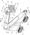
- FIG. 2 is a front left perspective view of the vehicle 10 of FIG. 1 .
- FIG. 3 is a rear right perspective view of the vehicle 10 of FIG. 1 .
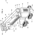
- FIG. 4 is a rear left perspective view of the vehicle 10 of FIG. 1 .
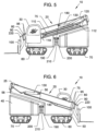
- FIG. 5 is a right side view of the vehicle 10 of FIG. 1 with cab 30 and telescoping boom 20 in a down position.
- FIG. 6 is a left side view of the vehicle 10 of FIG. 5 .
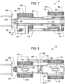
- FIG. 7 is a top view of the vehicle 10 of FIG. 5 .
- FIG. 8 is a bottom view of the vehicle 10 of FIG. 5 .
- FIG. 9 is a front view of the vehicle 10 of FIG. 5 .
- FIG. 10 is a rear view of the vehicle 10 of FIG. 5 .
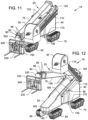
- FIG. 11 is a front right perspective view of the vehicle 10 of FIG. 1 with the telescoping boom 20 and articulating cab 30 fully down.
- FIG. 12 is a front right perspective view of the vehicle 10 of FIG. 12 with the telescoping boom 20 raised slightly and the cab 30 raised above the telescoping boom 20 for operator visibility.
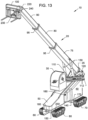
- FIG. 13 is a front right perspective view of the vehicle 10 of FIG. 12 with the telescoping boom 20 full raised and extended.
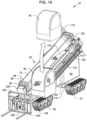
- FIG. 14 is a front right perspective view of the vehicle 10 of FIG. 11 showing range of motion of the articulating raiseable and lowerable cab 30.
- the all terrain versatile vehicle 10 can include a two body parts, which includes a rear body 40 and front body 40.
- the rear body 40 can include an engine compartment 40, which houses the vehicle engine and is the foundation of a rear track assembly 70.
- the rear track assembly 70 can include a right track attached on a lower rear right side of the rear body 40 and a left track attached on a lower rear left side of the rear body 40.
- the front track assembly 60 can include a right front track attached on a lower front right side of the front body 50 and a left front track attached on a lower front left side of the front body 50.
- the front body 50 with the superstructure can be attached to the rear body 40 with engine compartment, by superstructure hinge bracket 190 which is attached to an engine compartment engine bracket 200 by a hinge bracket pivot pin 210.
- the telescoping boom 20 can include a large boom section 75 with a middle boom section 80 that can telescope in and out of, and a small boom section 90 that can telescope in and out of the middle boom section 80.
- Stops 95 can limit the fully retracted positions of the middle boom section 80 within the large boom section 75, and the small boom section within the middle boom section 80.
- Similar internal stops, not shown, can also limit the fully extended positions of the middle boom section 80 relative to the large boom section 75, and the small boom section 90 relative to middle boom section 80.
- the bottom of the large boom section 75 can include a boom hinge pin 25 which rotatably attaches the telescoping boom 20 to an upper end super structure brackets 58, which together function as a boom hinge for allowing the telescoping boom 20 to pivot up and down relative to the upper end brackets 58 of the superstructure 50.
- a pair of hydraulic cylinders 130 (such as but not limited to those used in U.S. Patents: 6,024,232 to Helgesson and 4,632,630 to Maki et al. ) can be used.
- Each of the hydraulic cylinders 130 can have outer pivotal ends can be attached to both the large boom section 75 and the upper end superstructure brackets 58, where the telescoping hydraulic cylinders 130 can raise and lower the telescoping boom 20.
- the superstructure 50 can have a side view that appears to have a generally triangular configuration, and the superstructure 50 can include an upper ramped top with raised sides 56 for capturing the telescoping boom 20 when in its' most lowered position.
- the outer end of small boom section 90 of the telescoping boom 20 can include a fork assembly 100 with a fork bracket 220 attached thereon, by a fork assembly hinge pin 230, where a fork assembly hydraulic cylinder 240 (such as but not limited to those described in U.S. Pat. 4,632,630 to Maki et al. ) can adjust the angle of the fork bracket 220 relative to the telescoping boom 20.
- a fork assembly hydraulic cylinder 240 such as but not limited to those described in U.S. Pat. 4,632,630 to Maki et al.
- the vehicle 10 can include a cab 30 that can be raised and lowered from an upper hinged bracket 118 attached to an upper end of parallel cab linkage arms 110 which are attached to a lower hinged bracket 112 which is attached to an upper portion bracket 54 of the superstructure 50.
- a hydraulic cylinder 120 such as those described in U.S. Pat. 5,890,557 to Glass et al. , can be used to control the raising and lowering of the cab 30.
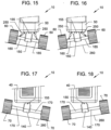
- FIG. 15 is a lower front view of the front track assembly 60 of the vehicle 10 which includes a front left track attached to a middle front track bracket 150 by a front left axle housing 160, and a front right track attached to the middle front track bracket by a front right axle 165, with the front track assembly tilted down to the right.
- FIG. 16 is another view of FIG. 15 with the front track assembly 60 tilted in an opposite orientation.
- the axle housings 160, 165 are able to adjust, via bracket pivot pin 155 which attaches the bottom of the front body 50 to the middle front bracket 50.
- the front track assembly 60 is able to be tiltable up and down based on hydraulic cylinders 250 (such as those described in U.S. Pat. 5,180,028 to Perrenoud, Jr. ), controlled by an operator in the cab 30, to ground level changes and keep the vehicle front body 50 and rear body 40 and superstructure level.
- FIG. 17 is a lower rear view of the vehicle 10 of the preceding figures of engine compartment (rear body) 40, rear track assembly 70, and rear axle 170 showing how the axle 170 is able to adjust to ground level changes via pivot pin 155 that attached a bottom of the rear body 40 to a middle rear bracket 140.
- the engine compartment (rear body 40) leveling feature is not hydraulically powered and is free-pivoting and follows the lead of the superstructure (front body 50.
- FIG. 18 is another view of FIG. 17 with the axle 170 tilted an opposite orientation.
- FIG. 19 is a bottom right perspective view of the vehicle 10 of the preceding figures showing the axle's 160, 165 and 170 and track assemblies 60, 70 parallel to one another and parallel to the superstructure (front body) 50.
- FIG. 20 is another perspective view of FIG. 19 showing how the front track assembly 60 with axles 160, 165 and pivoting bracket 150 and rear track assembly 70 with rear axle 170 and pivoting bracket 140 rotate about the axle hinge pins 155.
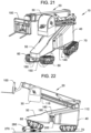
- FIG. 21 is a top right perspective view of the vehicle 10 of the preceding figures showing how the track assemblies 60 and 70 can articulate by rotating about and relative to their axles 160, 165, and 170, respectively.
- the front track assemblies 160, 165 can also be locked in any position.
- FIG. 22 is a right side view of vehicle 10 of FIG. 21 showing the utility of the articulating tracks of the front track assembly 60 in overcoming an obstacle 280, such as but not limited to a rock, log, or other obstacle, and the like.
- the articulating track assemblies 60, 70 can be used when the vehicle traverses ground surfaces with obstacle(s) 280, and/or a relatively level ground surface 270 and/or ground surfaces that are not level such as those shown in Figures 15-18 .
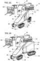
- FIG. 23 is a front right perspective view of the vehicle 10 of the preceding figures showing the rear engine compartment (rear body) 40 angled to the left relative to the superstructure on the front body 50.
- FIG. 24 is another view of FIG. 23 with the engine compartment (rear body) 40 angled to the right relative to the superstructure on the front body 50.
- FIG. 25 is a bottom view of the vehicle 10 of FIG. 24 .
- FIG. 26 is a bottom view of the vehicle 10 of FIG. 23 .
- the hinge components 190, 200, 210 allow for the front body 50 to articulate to the right or left relative to the rear body 40.
- a hydraulic cylinder(s), such as those previously described can be used to allow an operator in the cab 30 to control the angle orientation of the front body 50 to the rear body 40.
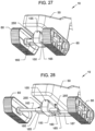
- FIG. 27 is a front bottom perspective view of the front body 50 with superstructure showing the axle housings 160, 165 and track assembly 60 comprising the left track and the right track, with the inner telescoping axles 163, 167 (shown in FIG. 28 ) being retracted into the respective axle housings 160, 165 in this view.
- FIG. 28 is another view of FIG. 27 with the inner extendable axles 163, 167 fully extended from their respective axle housings 160, 165, which places the right and left tracks further away from the superstructure (front body) 50 for increased stability over different ground surfaces.
- a pair of hydraulic cylinders 250 can separately control each of the extendable inner axles 163, 167 as needed by the operator in the cab 30.
- levelling features is shown in the preferred embodiment to not include the rear body (engine compartment) 40, the invention can also be used where both the front body (super structure) 50 and the rear body 50 both include hydraulic cylinder leveling controls.
- the cab can be in a fixed orientation relative to the vehicle, and not raisable or lowerable.
- While the preferred embodiments show the use of extendable and retractable tracks, the invention can be used without extendable and retractable tracks, where the tracks are in a fixed length position relative to one another.
- the vehicle tracks are shown in the preferred embodiments as oscillating, the vehicle tracks can be made without oscillating tracks, and the like.
- Example 1 An all terrain vehicle, comprising:
- Example 2 The all terrain vehicle of claim 1, wherein the front pair of tracks includes:
- Example 3 The all terrain vehicle of claim 2, further comprising: a tilting control for controlling tilting angle of the front pair of tracks.
- Example 4 The all terrain vehicle of claim 3, wherein the tilting control includes hydraulics.
- Example 5 The all terrain vehicle of claim 1, wherein the rear pair of tracks includes:
- Example 6 The all terrain vehicle of claim 1, wherein the front pair of tracks includes:
- Example 7 The all terrain vehicle of claim 6, further comprising:
- Example 8 The all terrain vehicle of claim 6, wherein the rear pair of tracks includes:
- Example 9 The all terrain vehicle of claim 1 , wherein the front pair of tracks includes:
- Example 10 The all terrain vehicle of claim 1 , wherein the extendable boom includes: telescoping boom members for allowing the forklift to extend outward and inward relative to the upper outer extended end of the angled superstructure on the vehicle.
- Example 11 The all terrain vehicle of claim 10, further comprising: a boom hinge member for allowing the boom to hinge up and down relative to the upper outer extended end of the angled superstructure.
- Example 12 The all terrain vehicle of claim 10, wherein the boom telescoping members include hydraulic cylinders.
- Example 13 The all terrain vehicle of claim 1 , further comprising: an articulating control for controlling articulating angle orientation of the articulating hinge attached between the front body and the rear body.
- Example 14 The all terrain vehicle of claim 13, wherein the articulating control includes: telescoping members for the controlling of the articulating angle orientation of the articulating hinge attached between the front body and the rear body.
- Example 15 The all terrain vehicle of claim 14, wherein the telescoping members include hydraulic cylinders.
- Example 16 The all terrain vehicle of claim 1 , further comprising:
- Example 17 The all terrain vehicle of claim 16, further comprising: arm telescoping members for controlling the cab to articulate up to the raised position and down to the lowered position.
- Example 18 The all terrain vehicle of claim 17, wherein the arm telescoping members include hydraulic cylinders.
- Example19 An all terrain vehicle, comprising:
- Example 20 The all terrain vehicle of claim 19, wherein the tool implement includes: a forklift attachment.
Landscapes
- Engineering & Computer Science (AREA)
- Transportation (AREA)
- Structural Engineering (AREA)
- Mechanical Engineering (AREA)
- Civil Engineering (AREA)
- Life Sciences & Earth Sciences (AREA)
- Geology (AREA)
- Chemical & Material Sciences (AREA)
- Combustion & Propulsion (AREA)
- Forklifts And Lifting Vehicles (AREA)
- Body Structure For Vehicles (AREA)
Applications Claiming Priority (3)
| Application Number | Priority Date | Filing Date | Title |
|---|---|---|---|
| US15/920,617 US10807847B2 (en) | 2018-03-14 | 2018-03-14 | All terrain versatile telescopic fork lift |
| PCT/US2019/020747 WO2019177808A1 (en) | 2018-03-14 | 2019-03-05 | All terrain versatile telescopic fork lift |
| EP19767501.0A EP3740452B1 (de) | 2018-03-14 | 2019-03-05 | Vielseitiger geländegängiger teleskopischer gabelstapler |
Related Parent Applications (2)
| Application Number | Title | Priority Date | Filing Date |
|---|---|---|---|
| EP19767501.0A Division EP3740452B1 (de) | 2018-03-14 | 2019-03-05 | Vielseitiger geländegängiger teleskopischer gabelstapler |
| EP19767501.0A Division-Into EP3740452B1 (de) | 2018-03-14 | 2019-03-05 | Vielseitiger geländegängiger teleskopischer gabelstapler |
Publications (1)
| Publication Number | Publication Date |
|---|---|
| EP4166492A1 true EP4166492A1 (de) | 2023-04-19 |
Family
ID=67906882
Family Applications (2)
| Application Number | Title | Priority Date | Filing Date |
|---|---|---|---|
| EP22205648.3A Pending EP4166492A1 (de) | 2018-03-14 | 2019-03-05 | Vielseitiger geländegängiger teleskopischer gabelstapler |
| EP19767501.0A Active EP3740452B1 (de) | 2018-03-14 | 2019-03-05 | Vielseitiger geländegängiger teleskopischer gabelstapler |
Family Applications After (1)
| Application Number | Title | Priority Date | Filing Date |
|---|---|---|---|
| EP19767501.0A Active EP3740452B1 (de) | 2018-03-14 | 2019-03-05 | Vielseitiger geländegängiger teleskopischer gabelstapler |
Country Status (5)
| Country | Link |
|---|---|
| US (2) | US10807847B2 (de) |
| EP (2) | EP4166492A1 (de) |
| CA (1) | CA3092590C (de) |
| MX (2) | MX388539B (de) |
| WO (1) | WO2019177808A1 (de) |
Families Citing this family (10)
| Publication number | Priority date | Publication date | Assignee | Title |
|---|---|---|---|---|
| IT201800009635A1 (it) * | 2018-10-19 | 2020-04-19 | Mdb Srl Con Socio Unico | Veicolo radiocomandato polivalente |
| US11420338B2 (en) * | 2018-12-27 | 2022-08-23 | Toyota Research Institute, Inc. | Assistive robot systems for container tilting |
| USD937908S1 (en) * | 2020-01-14 | 2021-12-07 | Kubota Corporation | Tractor |
| DE102020101114A1 (de) * | 2020-01-17 | 2021-07-22 | MagneCat UG (haftungsbeschränkt) | Linearmotorisch angetriebenes Raupenfahrzeug |
| JP7440319B2 (ja) * | 2020-03-26 | 2024-02-28 | 住友建機株式会社 | 作業機械 |
| US11077896B1 (en) * | 2020-06-04 | 2021-08-03 | Teletrax Equipment, Llc | Oscillating track system |
| US11091358B1 (en) * | 2020-09-18 | 2021-08-17 | Teletrax Equipment, Llc | Method and system for providing an improved all-terrain telehandler |
| US20230416059A1 (en) * | 2022-06-27 | 2023-12-28 | Oshkosh Corporation | Mobility mule |
| USD1001412S1 (en) * | 2022-10-11 | 2023-10-10 | Manitou Bf | Forklift truck |
| EP4458754A1 (de) * | 2023-05-03 | 2024-11-06 | Merlo Project S.r.l. | Hubfahrzeug mit kippbarem fahrerhaus |
Citations (9)
| Publication number | Priority date | Publication date | Assignee | Title |
|---|---|---|---|---|
| US4632630A (en) | 1983-05-03 | 1986-12-30 | Koehring Company | Forklift attachment |
| EP0360640A1 (de) * | 1988-08-22 | 1990-03-28 | Entreprises Bernard Baillargeon Inc. | Geländefahrzeug |
| US5180028A (en) | 1991-01-07 | 1993-01-19 | Perrenoud Jr Stephen A | Tractor implement orientation system |
| DE29621184U1 (de) | 1995-12-08 | 1997-04-10 | Karl Schaeff GmbH & Co. Maschinenfabrik, 74595 Langenburg | Schaufellader mit großer Ladehöhe |
| US5890557A (en) | 1996-09-03 | 1999-04-06 | Caterpillar Inc. | Apparatus and method for moving a tractor cab relative to a tractor body |
| US6024232A (en) | 1997-07-24 | 2000-02-15 | Kalmar Industries Sverige Ab | Boom truck |
| US20100044124A1 (en) * | 2005-11-23 | 2010-02-25 | Radke Daniel D | Articulated Dozer With Suspension And Suspension Lockout |
| CN104261280A (zh) * | 2014-09-17 | 2015-01-07 | 徐工集团工程机械股份有限公司 | 一种工程机械及其可变轨底盘装置 |
| US20180037278A1 (en) | 2015-02-13 | 2018-02-08 | Moorend Ltd | Apparatus arranged for converting a wheeled vehicle to a tracked vehicle |
Family Cites Families (35)
| Publication number | Priority date | Publication date | Assignee | Title |
|---|---|---|---|---|
| US3414072A (en) * | 1965-09-16 | 1968-12-03 | Lockheed Aircraft Corp | Vehicle capable of articulating about roll, pitch, and yaw axes |
| US3435908A (en) * | 1967-03-01 | 1969-04-01 | Caterpillar Tractor Co | Articulated crawler tractor construction |
| US3451494A (en) * | 1967-10-06 | 1969-06-24 | Int Harvester Co | Close-coupled articulated crawler tractor |
| US3741331A (en) * | 1970-08-21 | 1973-06-26 | Int Harvester Co | Close coupled frame steered all crawler tractor |
| DE2110200C3 (de) * | 1971-03-03 | 1974-01-31 | Maschinenbau Ulm Gmbh, 7900 Ulm | Planierhobel |
| US3789945A (en) * | 1971-11-04 | 1974-02-05 | Chalmers A Corp | Vehicle control module support |
| US3782491A (en) * | 1972-02-22 | 1974-01-01 | Trw Inc | Power steering system for adjustable track vehicles |
| GB1488810A (en) | 1973-12-20 | 1977-10-12 | Rubery Owen Mech Equipment Ltd | Straddle carriers |
| US4194584A (en) | 1978-07-17 | 1980-03-25 | Delany James F | Variable terrain vehicle |
| US4823852A (en) | 1987-02-05 | 1989-04-25 | Allied Systems Company | Tree feller-buncher |
| US5113958A (en) | 1990-05-23 | 1992-05-19 | Holden Thomas R | Snow travel vehicle |
| US5427195A (en) * | 1994-05-04 | 1995-06-27 | Int. Silvatech Ltd. | Hydraulic drive and steering systems for a vehicle |
| US5489114A (en) * | 1994-09-29 | 1996-02-06 | Kidde Industries, Inc. | Tie rod extendable and retractable telescopic axle assembly |
| US5607210A (en) * | 1994-12-21 | 1997-03-04 | Brazier; Glen | Wheel mount track conversion assembly |
| CA2157265C (en) | 1995-08-30 | 1999-02-02 | Donald Gauvin | Articulated vehicle |
| US6116362A (en) * | 1998-07-09 | 2000-09-12 | Case Corporation | Articulated vehicle |
| US6213490B1 (en) * | 1998-09-25 | 2001-04-10 | Case Corporation | Work vehicle with nested steering |
| US7195126B2 (en) | 2001-09-28 | 2007-03-27 | Kobelco Cranes Co., Ltd. | Self-propelled working machine |
| US7387314B2 (en) | 2004-02-11 | 2008-06-17 | White Robert E | Multi-configurable tractor |
| US7584812B2 (en) * | 2004-11-29 | 2009-09-08 | Deere & Company | Articulated dozer with suspension and suspension lockout |
| US7690738B2 (en) | 2005-05-31 | 2010-04-06 | Wilt H William B | Dynamically changing track support for tracked vehicle |
| CA2914568C (en) * | 2006-12-11 | 2018-05-01 | Vermeer Manufacturing Company | Apparatus for converting a wheeled vehicle to a tracked vehicle |
| JP2009197439A (ja) | 2008-02-20 | 2009-09-03 | Caterpillar Japan Ltd | 作業機械における干渉防止制御装置 |
| US7963361B2 (en) | 2008-09-24 | 2011-06-21 | Deere & Company | Steering axle transport positioning structure and method |
| US7997369B2 (en) | 2009-06-02 | 2011-08-16 | Exodus Machines, Inc. | Articulating cab assembly for excavator |
| US9908571B2 (en) * | 2010-03-26 | 2018-03-06 | Guntert & Zimmerman Const. Div., Inc. | Adjustable bolster swing legs for slipform paving machines |
| CA2742731A1 (en) * | 2011-06-15 | 2012-12-15 | Carl Audet | All terrain vehicle |
| US8910732B1 (en) | 2011-07-13 | 2014-12-16 | Link-Belt Construction Equipment Co., L.P., Lllp | Axle arrangement for mobile crane and related methods |
| US8888122B2 (en) | 2012-03-19 | 2014-11-18 | Jlg Industries, Inc. | Pivoting axle system |
| US9522708B2 (en) | 2012-08-03 | 2016-12-20 | Zhengxu He | Deformable track support for tracked vehicles |
| SE538096C2 (sv) | 2013-05-08 | 2016-03-01 | BAE Systems Hägglunds Aktiebolag | Lastbärande ram och fordon försett med lastbärande ram |
| US9180747B2 (en) * | 2013-10-14 | 2015-11-10 | Agco Corporation | System and method of adjusting the chassis height of a machine |
| PL3177561T3 (pl) | 2014-08-04 | 2022-01-31 | Almac S.R.L. | Zespół poziomujący dla napowietrznych platform roboczych |
| US9682736B1 (en) | 2016-04-07 | 2017-06-20 | Cnh Industrial America Llc | Implement steerable track assembly pivotable about three axes |
| AU2017248349B2 (en) | 2016-04-08 | 2021-11-11 | Oshkosh Corporation | Leveling system for lift device |
-
2018
- 2018-03-14 US US15/920,617 patent/US10807847B2/en active Active
-
2019
- 2019-03-05 EP EP22205648.3A patent/EP4166492A1/de active Pending
- 2019-03-05 MX MX2020009499A patent/MX388539B/es unknown
- 2019-03-05 CA CA3092590A patent/CA3092590C/en active Active
- 2019-03-05 EP EP19767501.0A patent/EP3740452B1/de active Active
- 2019-03-05 WO PCT/US2019/020747 patent/WO2019177808A1/en not_active Ceased
-
2020
- 2020-08-28 US US17/006,451 patent/US11208307B2/en active Active
- 2020-09-11 MX MX2021013664A patent/MX2021013664A/es unknown
Patent Citations (9)
| Publication number | Priority date | Publication date | Assignee | Title |
|---|---|---|---|---|
| US4632630A (en) | 1983-05-03 | 1986-12-30 | Koehring Company | Forklift attachment |
| EP0360640A1 (de) * | 1988-08-22 | 1990-03-28 | Entreprises Bernard Baillargeon Inc. | Geländefahrzeug |
| US5180028A (en) | 1991-01-07 | 1993-01-19 | Perrenoud Jr Stephen A | Tractor implement orientation system |
| DE29621184U1 (de) | 1995-12-08 | 1997-04-10 | Karl Schaeff GmbH & Co. Maschinenfabrik, 74595 Langenburg | Schaufellader mit großer Ladehöhe |
| US5890557A (en) | 1996-09-03 | 1999-04-06 | Caterpillar Inc. | Apparatus and method for moving a tractor cab relative to a tractor body |
| US6024232A (en) | 1997-07-24 | 2000-02-15 | Kalmar Industries Sverige Ab | Boom truck |
| US20100044124A1 (en) * | 2005-11-23 | 2010-02-25 | Radke Daniel D | Articulated Dozer With Suspension And Suspension Lockout |
| CN104261280A (zh) * | 2014-09-17 | 2015-01-07 | 徐工集团工程机械股份有限公司 | 一种工程机械及其可变轨底盘装置 |
| US20180037278A1 (en) | 2015-02-13 | 2018-02-08 | Moorend Ltd | Apparatus arranged for converting a wheeled vehicle to a tracked vehicle |
Also Published As
| Publication number | Publication date |
|---|---|
| MX2021013664A (es) | 2021-12-10 |
| US20200399103A1 (en) | 2020-12-24 |
| EP3740452C0 (de) | 2023-06-07 |
| EP3740452A4 (de) | 2021-04-07 |
| WO2019177808A1 (en) | 2019-09-19 |
| US10807847B2 (en) | 2020-10-20 |
| MX388539B (es) | 2025-03-20 |
| CA3092590C (en) | 2021-09-07 |
| CA3092590A1 (en) | 2019-09-19 |
| US11208307B2 (en) | 2021-12-28 |
| US20190322506A1 (en) | 2019-10-24 |
| EP3740452A1 (de) | 2020-11-25 |
| MX2020009499A (es) | 2021-12-07 |
| EP3740452B1 (de) | 2023-06-07 |
Similar Documents
| Publication | Publication Date | Title |
|---|---|---|
| US11208307B2 (en) | All terrain versatile telescopic fork lift | |
| US4395191A (en) | Excavator-hoist construction vehicle | |
| US4265326A (en) | Rolling and stepping vehicle | |
| US20070240928A1 (en) | Compact construction vehicle with improved mobility | |
| CN101808849B (zh) | 车架可扩展的作业车 | |
| US10131387B2 (en) | Construction vehicle having a tippable chassis | |
| US9850640B2 (en) | Working machine | |
| US11091358B1 (en) | Method and system for providing an improved all-terrain telehandler | |
| WO1989000928A1 (en) | Cross-country vehicle | |
| EP1560987B1 (de) | Baggerlader | |
| CA2421703A1 (en) | Boom and linkage mechanism for skid-steer loader | |
| US20240359550A1 (en) | All-Terrain Construction Equipment and Methods | |
| JPH0433930B2 (de) | ||
| ITTO980765A1 (it) | Veicolo utilizzabile come sollevatore a trattore agricolo. | |
| US4363409A (en) | Multi-purpose utility vehicle | |
| US4431363A (en) | Articulated material handling machine | |
| US4183711A (en) | Mobile power shovel | |
| US4071090A (en) | Motorgrader implement mounting arrangement | |
| US4329796A (en) | Multi-use excavating and load handling machine | |
| US11077896B1 (en) | Oscillating track system | |
| US20050262741A1 (en) | Variable-position stabilizer leg | |
| BRPI0410104B1 (pt) | Veículo para todo terreno com elementos ambulatórios | |
| CA1258827A (en) | Excavator/loader | |
| GB2066189A (en) | Multi-purpose utility vehicle | |
| GB2050264A (en) | Rough terrain vehicle suspension |
Legal Events
| Date | Code | Title | Description |
|---|---|---|---|
| PUAI | Public reference made under article 153(3) epc to a published international application that has entered the european phase |
Free format text: ORIGINAL CODE: 0009012 |
|
| STAA | Information on the status of an ep patent application or granted ep patent |
Free format text: STATUS: THE APPLICATION HAS BEEN PUBLISHED |
|
| AC | Divisional application: reference to earlier application |
Ref document number: 3740452 Country of ref document: EP Kind code of ref document: P |
|
| AK | Designated contracting states |
Kind code of ref document: A1 Designated state(s): AL AT BE BG CH CY CZ DE DK EE ES FI FR GB GR HR HU IE IS IT LI LT LU LV MC MK MT NL NO PL PT RO RS SE SI SK SM TR |
|
| STAA | Information on the status of an ep patent application or granted ep patent |
Free format text: STATUS: REQUEST FOR EXAMINATION WAS MADE |
|
| 17P | Request for examination filed |
Effective date: 20230704 |
|
| RBV | Designated contracting states (corrected) |
Designated state(s): AL AT BE BG CH CY CZ DE DK EE ES FI FR GB GR HR HU IE IS IT LI LT LU LV MC MK MT NL NO PL PT RO RS SE SI SK SM TR |
|
| STAA | Information on the status of an ep patent application or granted ep patent |
Free format text: STATUS: EXAMINATION IS IN PROGRESS |
|
| 17Q | First examination report despatched |
Effective date: 20241209 |