EP4166745A1 - Rollladen-/raffstore-kasten - Google Patents
Rollladen-/raffstore-kasten Download PDFInfo
- Publication number
- EP4166745A1 EP4166745A1 EP22201240.3A EP22201240A EP4166745A1 EP 4166745 A1 EP4166745 A1 EP 4166745A1 EP 22201240 A EP22201240 A EP 22201240A EP 4166745 A1 EP4166745 A1 EP 4166745A1
- Authority
- EP
- European Patent Office
- Prior art keywords
- roller shutter
- leg
- venetian blind
- free end
- insulating
- Prior art date
- Legal status (The legal status is an assumption and is not a legal conclusion. Google has not performed a legal analysis and makes no representation as to the accuracy of the status listed.)
- Granted
Links
Images


Classifications
-
- E—FIXED CONSTRUCTIONS
- E06—DOORS, WINDOWS, SHUTTERS, OR ROLLER BLINDS IN GENERAL; LADDERS
- E06B—FIXED OR MOVABLE CLOSURES FOR OPENINGS IN BUILDINGS, VEHICLES, FENCES OR LIKE ENCLOSURES IN GENERAL, e.g. DOORS, WINDOWS, BLINDS, GATES
- E06B9/00—Screening or protective devices for wall or similar openings, with or without operating or securing mechanisms; Closures of similar construction
- E06B9/02—Shutters, movable grilles, or other safety closing devices, e.g. against burglary
- E06B9/08—Roll-type closures
- E06B9/11—Roller shutters
- E06B9/17—Parts or details of roller shutters, e.g. suspension devices, shutter boxes, wicket doors, ventilation openings
- E06B9/17007—Shutter boxes; Details or component parts thereof
-
- E—FIXED CONSTRUCTIONS
- E06—DOORS, WINDOWS, SHUTTERS, OR ROLLER BLINDS IN GENERAL; LADDERS
- E06B—FIXED OR MOVABLE CLOSURES FOR OPENINGS IN BUILDINGS, VEHICLES, FENCES OR LIKE ENCLOSURES IN GENERAL, e.g. DOORS, WINDOWS, BLINDS, GATES
- E06B9/00—Screening or protective devices for wall or similar openings, with or without operating or securing mechanisms; Closures of similar construction
- E06B9/02—Shutters, movable grilles, or other safety closing devices, e.g. against burglary
- E06B9/08—Roll-type closures
- E06B9/11—Roller shutters
- E06B9/17—Parts or details of roller shutters, e.g. suspension devices, shutter boxes, wicket doors, ventilation openings
- E06B9/17007—Shutter boxes; Details or component parts thereof
- E06B9/17015—Shutter boxes; Details or component parts thereof made of at most two pieces; Front opening details
-
- E—FIXED CONSTRUCTIONS
- E06—DOORS, WINDOWS, SHUTTERS, OR ROLLER BLINDS IN GENERAL; LADDERS
- E06B—FIXED OR MOVABLE CLOSURES FOR OPENINGS IN BUILDINGS, VEHICLES, FENCES OR LIKE ENCLOSURES IN GENERAL, e.g. DOORS, WINDOWS, BLINDS, GATES
- E06B9/00—Screening or protective devices for wall or similar openings, with or without operating or securing mechanisms; Closures of similar construction
- E06B9/24—Screens or other constructions affording protection against light, especially against sunshine; Similar screens for privacy or appearance; Slat blinds
- E06B9/26—Lamellar or like blinds, e.g. venetian blinds
- E06B9/28—Lamellar or like blinds, e.g. venetian blinds with horizontal lamellae, e.g. non-liftable
- E06B9/30—Lamellar or like blinds, e.g. venetian blinds with horizontal lamellae, e.g. non-liftable liftable
- E06B9/32—Operating, guiding, or securing devices therefor
- E06B9/323—Structure or support of upper box
-
- E—FIXED CONSTRUCTIONS
- E06—DOORS, WINDOWS, SHUTTERS, OR ROLLER BLINDS IN GENERAL; LADDERS
- E06B—FIXED OR MOVABLE CLOSURES FOR OPENINGS IN BUILDINGS, VEHICLES, FENCES OR LIKE ENCLOSURES IN GENERAL, e.g. DOORS, WINDOWS, BLINDS, GATES
- E06B9/00—Screening or protective devices for wall or similar openings, with or without operating or securing mechanisms; Closures of similar construction
- E06B9/02—Shutters, movable grilles, or other safety closing devices, e.g. against burglary
- E06B9/08—Roll-type closures
- E06B9/11—Roller shutters
- E06B9/17—Parts or details of roller shutters, e.g. suspension devices, shutter boxes, wicket doors, ventilation openings
- E06B2009/17069—Insulation
Definitions
- the present invention relates generally to devices for accommodating roller shutters or venetian blinds and the like.
- Roller shutters / venetian blind boxes that are integrated into the outer wall of a building above a window or door are known. It is also known to provide such roller shutter/external venetian blind boxes with a decentralized room ventilation, which can convey air from inside the building through the roller shutter/external venetian blind box to the outside and vice versa.
- the present invention provides a roller shutter/venetian blind box according to the independent claim. Embodiments and variants thereof are specified in the dependent claims.
- the invention relates to a roller shutter/external venetian blind box for accommodating a roller shutter or external venetian blind, comprising a base body which provides a roller shutter/external venetian blind space for arranging the roller shutter or external venetian blind and an air duct.
- the roller shutter/external venetian blind box can have an insulating crescent that separates the roller shutter/external venetian blind space and the air duct.
- the use of an insulating sickle is intended in particular for embodiments in which the roller shutter/Raff Store box is used for roller shutters.
- an insulation crescent can also be used. In the case of external venetian blinds, however, designs without an insulating crescent are also possible.
- the base body includes a first leg with a free end.
- the roller shutter/venetian blind box further includes an airfoil disposed on an inner side of the first leg and in fluid communication with the air duct, the airfoil being configured to direct air from the air duct into the roller shutter/venetian blind space to direct. Air from the roller shutter/external venetian blind area can also be routed into the air duct via the air guide element.
- the air guiding element can be detachably arranged.
- a force-fitting, form-fitting, clamping, locking, snapping, screwing, adhesive connection(s) or combinations thereof can be used.
- the air guiding element can be arranged on the inside of the first leg at a distance from the free end of the first leg.
- the first leg tapers from its free end in the direction of the air guide element. This can in particular be understood to mean that the width of the first leg at or adjacent to the free end is greater than the width of the first leg in a region remote therefrom, preferably in the region of the air guiding element.
- the tapering of the first leg can be achieved by a corresponding design of its inside, whereas an outside of the first leg is designed in such a way that it does not contribute to the tapering.
- the insulating sickle can be supported with a first end on the inside of the first leg and/or can be supported on the air guiding element.
- the support can be detachable.
- a force-fitting, form-fitting, clamping, latching, snap, screw, adhesive connection(s) or combinations thereof can be used.
- the insulating sickle can be supported with a second end on a stop formed in or on the base body.
- the support can be detachable.
- a force-fitting, form-fitting, clamping, latching, snap, screw, adhesive connection(s) or combinations thereof can be used.
- the stop can be formed, for example, on an inside of the base body, which limits the space for the roller shutter/external venetian blind.
- the stop can be a recess in the base body.
- the base body can have a second leg with a free end.
- An insulating wedge can be provided, which is arranged at the free end of the second leg.
- the dam wedge may include a portion extending from the free end of the second leg which defines the size of an opening extending between a free end of the dam wedge and the free end of the first leg.
- the curtain of a roller shutter or slats of a venetian blind can be moved through this opening.
- the opening may have a width in the range 50-150 millimeters, preferably in the ranges 70-90 millimeters or 130-150 millimeters.
- the base body can have an inspection opening that extends between the free end of the first leg and the free end of the second leg.
- the inspection opening can have a width in the range of 180-230 millimeters
- the roller shutter/external venetian blind box can have an installation height in the range of 300-350 millimeters, preferably in the range of 330 millimeters.
- the roller shutter/external venetian blind space can comprise a hollow-cylindrical space whose cross section has a radius in the range of 80-110 millimeters, preferably in the range of 105 millimeters, transversely to the longitudinal axis.
- the arrangement of the roller shutter or external venetian blind can have a cross-section with respect to its longitudinal axis, the cut surface of which has an inner circle radius in the range of mm.
- a filler piece can be provided in the roller shutter/external venetian blind space which partially fills the roller shutter/external venetian blind space.
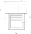
- FIG. 1 shows schematically a roller shutter / venetian blind box 2, which is installed over a window 4 in an outer wall 6 of the building.
- roller shutter/external venetian blind box 2 can also be placed below or on any other side of the window. Furthermore, the roller shutter/venetian blind box 2 can also be used for a door or another type of wall opening in an outer wall 6 of a building.
- the roller shutter/external venetian blind box 2 is integrated into the building wall 6, preferably in such a way that the outside of the roller shutter/external venetian blind box 2 or the plaster and/or insulation applied thereto are essentially in one plane with the outer wall 6 of the building lie, so there is a continuous surface.
- the roller shutter/external venetian blind box 2 can at least partially protrude outwards from the outer wall 6 of the building or be attached to the outside of the latter.
- roller shutter/external venetian blind box 2 is cuboid with a length L and a height H and, for example, in 2 indicated width B.
- the roller shutter / venetian blind box 2 can be shaped so that it can be used for example for a window or door, the / whose glare and / or
- sash frame is curved at the top, or for a window or door used in conjunction with an arched lintel.
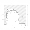
- FIG. 2 shows a cross section of the roller shutter / outdoor blind box 2 along the section AA of 1 .
- the embodiment in 2 comprises a base body 8, an air guiding element 10, an insulating sickle 12, an air duct 14 and a roller shutter/venetian blind space 16.
- the base body 8 is preferably produced using one or more materials with good thermal and preferably also acoustic insulation properties.
- materials include, for example, EPS, XPS, NEOPOR, and all types of polystyrene.
- the base body 8 comprises a first leg 18 which is formed by the part of the base body 8 which, in relation to the drawings, starts slightly above a first end 12a of the insulating sickle 12 and extends downward from there.
- the first leg 18 has a free end 20 .
- the free end 20 has a substantially planar end face extending substantially in the width B direction.
- the end face of the free end of the 20 extends in a direction that includes an angle with the width B.
- the end surface of the free end 20 can be substantially planar and extend obliquely from bottom right to top left or top right to bottom left with respect to the plane of the drawing.
- the free end 20 may have an end face that is curved in the plane defined by the height H and width B .
- the end surface can be U-shaped in order to be able to accommodate a sealing element and/or cabling, for example, or a fastening for a plaster rail, which will be explained in more detail below.
- the first leg 18 has a smaller width (i.e. cross-section in the direction of the width B) at its upper end as shown, i.e. the free end 20, than at its free end 20.
- this is accomplished on the inner surface 22 of the first leg 18 by having the inner surface 22 extend from a location 22a where the first leg 18 has a first width to a location 22b where the first leg 18 has a second width that is smaller than the second width.
- the inside 22 is essentially flat and extends—in the cross section shown—in a straight line between the point 22a and the point 22b.
- the inner side 22 can be curved, for example in such a way that it is concave or convex when viewed from above (i.e. when looking at the inner side 22 in the direction of width B according to the illustration).
- location 22a is spaced from free end 20 with the width of the leg between location 22a and free end 20 being substantially constant.
- the first leg 18 can be made more stable and/or stiffer in the area of its free end 20 .
- This variant can also make it easier to attach further components to the first leg 18 at and/or adjacent to the free end 20 .
- the point 22A is at the free end 20. In this way, the space that is created by reducing the width of the first leg 18 in the direction of the air guide element 10 can be increased.
- the outer side 24 of the first leg 18 preferably forms part of the outer side 26 of the base body 8, which forms part of the outer surface of the building wall 6 when used as intended. This ensures that the building wall 6 has an essentially continuous surface on the outside.
- the air guiding element 10 is arranged on the inside 22 of the first leg 18 at a distance from the free end of the first leg 18 .
- the air guiding element 10 can be attached there by means of a force-fitting, form-fitting, clamping, locking, snapping, screwing or adhesive connection or a combination of two or more such connections.
- the air guiding element 10 provides a fluid connection, in particular for air, between the air duct 14 and the roller shutter/venetian blind space 16 .
- the air duct 14 can be connected to a so-called decentralized ventilation system (not shown), which has a fan (or other means) to convey air from the interior of the building to the outside, e.g. to remove warmer air from the interior of the building for interior cooling and to supply colder air from the outside to the interior of the building and/or to remove colder air from the interior of the building for interior heating and to supply warmer air from the outside to the interior of the building.
- a fan or other means to convey air from the interior of the building to the outside, e.g. to remove warmer air from the interior of the building for interior cooling and to supply colder air from the outside to the interior of the building and/or to remove colder air from the interior of the building for interior heating and to supply warmer air from the outside to the interior of the building.
- Air can be conveyed from the air duct 14 through the air guiding element 10 into the roller shutter/external venetian blind space 16 by means of the fan. This allows air to be removed from inside the building. Conversely, it is possible to convey air from the roller shutter/venetian blind room 16 through the air guide element 10 into the air duct 14 by means of the fan, as a result of which outside air can get into the building interior.
- the air guide element 10 is designed as a double web plate.
- a double-walled plate comprises two substantially parallel plates which are connected by webs extending perpendicularly thereto.
- a double-walled plate thus provides channels with a rectangular cross section.
- the airfoil 10 may include one or more channels (e.g., round in cross-section) provided in other ways.
- the insulating sickle 12 separates the air duct 14 and the roller shutter/external venetian blind space 16, preferably in such a way that a fluid connection between the air duct 14 and the roller shutter/external venetian blind space 16 only exists via the air guiding element 10.
- the insulating sickle 12 interacts with the first end 12a and the inside 22 of the first leg 18 above the air guiding element 10 and/or the air guiding element 10 .
- the first end 12a of the insulating sickle 12 can be connected to the inside 22 of the first leg 18 above the air guide element 10 and/or to the air guide element 10 by means of a force-fitting, form-fitting, clamping, latching, snap, screw or adhesive connection or combination be attached by two or more such connections.
- the first end 12a of the insulating sickle has a shoulder 12c, by means of which the insulating sickle is supported on the inside 22 of the first leg 18 above the air guiding element 10 and on the air guiding element 10.
- the support can be designed to be detachable.
- the base body 8 has an inner side 28 which has a cross-section essentially in the shape of a segment of a circle and forms part of the boundary of the space 16 for the roller shutter/external venetian blind when roller shutters are used.
- a stop 30 is formed in the base body 8 at the upper end of the inner side 28 as shown.
- the insulating sickle 12 interacts with the stop 30 formed on the inside 28 of the base body 8.
- the second end 12b of the insulating sickle 12 can interact with the stop 28 by means of a force-fitting, form-fitting, clamping, locking, snapping, screwing or adhesive connection or a combination of two or more such connections.
- the insulating crescent 12 preferably has an inner side 12d which has a cross section essentially in the shape of a segment of a circle and forms part of the boundary of the roller shutter/external venetian blind space 16 .
- the insulating sickle 12, the stop 28 and the inside 28 of the base body 8 are preferably shaped and/or arranged in such a way that the inside 12d of the insulating sickle 12 and the inside 28 of the base body 8 form an essentially uninterrupted surface (apart from the area where the two inner sides adjoin each other), in particular in such a way that the cross section of this surface also has a cross section that is essentially in the shape of a segment of a circle.
- the insulating sickle 12 can be firmly connected to the base body 8 and optionally to the air guiding element 10 .
- this can be achieved by an insulating sickle 12 made of an at least partially elastic material, which allows insulating sickle 12 to be fixed at the first end 12a by means of its shoulder 12c on the inside 22 of the first leg above the air guiding element 10 and/or the air guiding element 10 and to support the second end 12b of the insulating sickle 12 on the stop 30 of the base body 8, to latch it or the like.
- the base body 8 has a second leg 32 .
- the second leg 32 of the base body has an inside 32a and an outside 32b, and a free end 32c.
- the inner side 32a of the second leg 32 adjoins the inner side 28 of the base body and can have a step 32d.
- the inner side 34 of the base body 8 i.e. the side of the base body that forms part of the inner surface of the building wall 6 when the roller shutter/external venetian blind box 2 is used as intended, includes the inner side 32b of the second leg 32. This ensures that the building wall 6 also has an essentially continuous surface on the outside.
- the free end 32c of the second leg 32 may include a protruding structure 36 .
- the distance on the one hand between the inner side 32a of the second leg 32 or, if the step 32d is present, the distance between the part of the inner side 32 shown below the step 32d and on the other hand the free end 20 of the first leg 18 defines an inspection opening 38.
- the inspection opening 38 is an opening through which the roller shutter/external venetian blind space 16 can be accessed, e.g. to install/remove or service a roller shutter there.
- FIG 3 illustrates embodiments in which a cleaning rail 40 already mentioned above and an insulating wedge 42 are present, which can be used for roller shutters when using the roller shutter/external venetian blind box 2 .
- the plaster rail 40 can serve as a plaster finishing profile for plaster applied to the outside of the first leg 18 .
- the cleaning rail 40 can be designed as a drip edge.
- the insulating wedge 42 has a fastening area 42a, a free end 42b, an inner side 42c delimiting the roller shutter/external venetian blind space 16, and an underside 42d.
- the fastening area 42a is used for the preferably detachable connection (e.g. by means of screws) of the insulating wedge 42 on the second leg 32 of the base body 8.
- the fastening area 42a is designed in such a way that it has surfaces which are shaped to complement the inside 32a and the free end 32c of the second leg 32 of the base body 8 .
- the part of the insulating wedge 42 between the free end 42b of the insulating wedge 42 and the surface of the fastening region 42a designed to complement the inside 32a of the second leg 32 of the base body 8 has a length LD.
- the length LD determines the size of an outlet opening 44 of the roller shutter/external venetian blind box 2.
- the outlet opening 44 extends between the free end 20 of the first leg 18 of the base body 8 and the free end 44b of the insulating wedge 42.
- the outlet opening 44 is the Opening through which a roller shutter can be lowered and pulled up.
- the inner side 42c of the insulating wedge 42 has a cross section in the shape of a segment of a circle.
- the cross-sections in the shape of a segment of a circle of the inside 12d of the insulating crescent 12, the inside 28 of the base body 8 and the inside 42c of the insulating wedge are segments of a circle with a common center point M center M is located.
- 4 11 illustrates embodiments that also use a plaster rail 40 and an insulating wedge 42, the insulating wedge 42 being provided here for external venetian blinds when using the roller shutter/external venetian blind box 2.
- the above explanations apply 3 for the 4 accordingly, unless expressly stated otherwise.
- the outlet opening 44 of 4 is the opening through which a venetian blind can be lowered and pulled up.
- the outlet opening 44 of 3 of less than that of 4 .
- the insulating wedge 42 of 4 has a shorter length LD.
- a filler piece 46 can be provided when using the roller shutter/external venetian blind box 2 for external venetian blinds.
- the filler piece 46 can fill that part of the roller shutter/external venetian blind space 16 that is not required for external venetian blinds.
- the present invention may further have the following features and advantages.
- the air guiding element can have a length in the range from 30 to 90, preferably 60 millimeters.
- An air guiding element can thus be used that is significantly shorter than previously known air guiding elements. This reduces "drag" when air is forced through the airfoil.
- the height H of the roller shutter/external venetian blind box also known as the installation height, can be in the range from 300 to 350, preferably 330 millimeters. This makes it possible to provide roller shutters/external venetian blind boxes with installation heights that can simplify the integration of a roller shutter/external venetian blind box into a given brickwork grid (e.g. standard grid). Furthermore, the use of door and window frames with standard dimensions is supported.
- the width B of the roller shutter/external venetian blind box also known as the installation width, can range from 250 to 490 millimeters.
- the roller shutter/external venetian blind box can be installed flush on the inside and outside in the outer wall of the building.
- a brick case 48 is used for the base body 8, which variant shown has a substantially U-shaped cross-section with respect to the longitudinal axis L transversely to the longitudinal axis.
- the brick box 48 can be referred to as a "housing”.
- the filling material 50 can include, for example, EPS, XPS, NEOPOR, as well as all types of polystyrene, as well as mixtures or combinations of two or more such materials.
- the filling material 50 is designed in such a way that, viewed together, the brick box 48 and the filling material 50 have a cross section transverse to the longitudinal axis that corresponds to the cross section of the base body 2 corresponds, at least is comparable with this one with regard to the features that have been described as being usable in the invention. Therefore, unless otherwise stated below, reference is made to the above statements, which also apply here without repetition.
- the first leg 18 of the base body 8 is provided by the left leg of the brick case 48 according to the illustration.
- the second leg 32 of the base body 8 is provided by the right leg of the brick case 48 and the filling material arranged there.
- the stop 30 of the base body 8 is formed in the filling material 50 .
- the base body 8 comprising the brick box 48 and the filling material 50 can also, as explained above, be used with an insulating wedge 42 which allows the accommodation and use of a roller shutter or a venetian blind.
- an insulating wedge 42 which allows the accommodation and use of a roller shutter or a venetian blind.
- FIG 5 referenced which referred to the use of the brick box 48 and the filling material 50 comprehensive base body 8 with an insulating wedge 42 for shutters.
- the above statements regarding 3 apply here accordingly.
- Also for the above statements regarding 4 apply here accordingly if the base body 8 comprising the brick box 48 and the filling material 50 is used with an insulating wedge 42 for external venetian blinds.
- Reference List Roller shutter / venetian blind box 2 Window 4 building wall 6 length / longitudinal axis L Height H Broad B Cross-section perpendicular to the longitudinal axis L aa body 8th air deflector 10 insulating sickle 12 First end of the insulation crescent, which interacts with the inside of the first leg 12a Second end of the insulation sickle, which interacts with the stop formed on the base body 12b Paragraph of the insulating sickle 12c Inside of the insulating sickle 12d air duct 14 Roller shutters/Raffstore room 16 First leg of the body 18 Free end of the first leg 18 20 Inside of the first limb 22 Point with greater width of the first leg 22a Place with smaller width of the first leg 22b outside of the first leg 24 Outside of the base body, which connects to the outside of the first leg 26 Inside of the base body with a cross-section in the shape of a segment of a circle 28 Stop on the inside of the base body 30 Second leg of the body 32 inner side of the second leg 32a Outside of the second leg 32b Free end of
Landscapes
- Engineering & Computer Science (AREA)
- Structural Engineering (AREA)
- Architecture (AREA)
- Civil Engineering (AREA)
- Blinds (AREA)
Abstract
Description
- Die vorliegende Erfindung betrifft im Allgemeinen Vorrichtungen zur Aufnahme von Rollläden oder Raffstores und dergleichen.
- Rollladen-/Raffstore-Kästen, die über einem Fenster oder Tür in die Gebäudeaußenwand integriert sind, sind bekannt. Auch ist es bekannt, solche Rollladen-/Raffstore-Kästen mit einer dezentralen Raumlüftung zu versehen, die Luft aus dem Gebäudeinneren durch den Rollladen-/Raffstore-Kasten nach außen befördern kann und umgekehrt.
- Die vorliegende Erfindung stellt Rollladen-/Raffstore-Kasten gemäß dem unabhängigen Anspruch bereit. Ausführungsformen und Varianten davon sind in den abhängigen Patentansprüchen angegeben.
- Im Allgemeinen betrifft die Erfindung einen Rollladen-/Raffstore-Kasten zur Aufnahme eines Rollladens oder Raffstores, umfassend einen Grundkörper, der einen Rollladen-/Raffstore-Raum zur Anordnung des Rollladens oder Raffstores und einen Luftkanal bereitstellt.
- Der Rollladen-/Raffstore-Kasten kann eine Dämmsichel aufweisen, die den Rollladen-/Raffstore-Raum und den Luftkanal trennt. Die Verwendung einer Dämmsichel ist insbesondere bei Ausführungsformen vorgesehen, bei denen der Rollladen-/Raff Store-Kasten für Rollläden verwendet wird. Bei Verwendungen für Raffstores kann ebenfalls eine Dämmsichel verwendet werden. Bei Raffstores sind allerdings auch Ausführungsformen ohne Dämmsichel möglich.
- Ferner umfasst der Grundkörper einen ersten Schenkel mit einem freien Ende.
- Ferner umfasst der Rollladen-/Raffstore-Kasten ein Luftleitelement, das an einer Innenseite des ersten Schenkels angeordnet ist und in Fluidverbindung mit dem Luftkanal steht, wobei das Luftleitelement ausgelegt ist, Luft aus dem Luftkanal in den Rollladen-/Raffstore-Raum zu leiten. Über das Luftleitelement kann auch Luft aus dem Rollladen-/Raffstore-Raum in den Luftkanal geleitet werden.
- Das Luftleitelement kann lösbar angeordnet sein.
- Zur Anordnung des Luftleitelements an der Innenseite des ersten Schenkels können eine kraftschlüssige, formschlüssige, Klemm-, Rast-, Schnapp-, Schraub-, Kleb-Verbindung(en) oder Kombinationen davon verwendet werden.
- Das Luftleitelement kann an der Innenseite des ersten Schenkels beabstandet vom freien Ende des ersten Schenkels angeordnet sein.
- Der erste Schenkel verjüngt sich von seinem freien Ende in Richtung hin zum Luftleitelement. Darunter kann insbesondere verstanden werden, dass die Breite des ersten Schenkels am oder benachbart zum freien Ende größer ist als die Breite des ersten Schenkels in einem davon entfernten Bereich, vorzugsweise in Bereich des Luftleitelements.
- Die Verjüngung des ersten Schenkels kann durch eine entsprechende Ausbildung seiner Innenseite erreicht werden, wohingegen eine Außenseite des ersten Schenkels so ausgebildet ist, dass sie nicht zur Verjüngung beiträgt.
- Die Dämmsichel kann sich mit einem ersten Ende an der Innenseite des ersten Schenkels abstützen und/oder dem Luftleitelement abstützen. Die Abstützung kann lösbar sein. Für diese Abstützung der Dämmsichel können eine kraftschlüssige, formschlüssige, Klemm-, Rast-, Schnapp-, Schraub-, Kleb-Verbindung(en) oder Kombinationen davon verwendet werden.
- Die Dämmsichel kann sich mit einem zweiten Ende an einem im oder am Grundkörper ausgeformten Anschlag abstützen. Die Abstützung kann lösbar sein. Für diese Abstützung der Dämmsichel können eine kraftschlüssige, formschlüssige, Klemm-, Rast-, Schnapp-, Schraub-, Kleb-Verbindung(en) oder Kombinationen davon verwendet werden.
- Der Anschlag kann beispielsweise an einer Innenseite des Grundkörpers ausgebildet sein, die Rollladen-/Raffstore-Raum begrenzt.
- Der Anschlag kann eine Ausnehmung im Grundkörper sein.
- Den Grundkörper kann einen zweiten Schenkel mit einem freien Ende aufweisen.
- Es kann ein Dämmkeil vorgesehen sein, der an dem freien Ende des zweiten Schenkels angeordnet ist.
- Der Dämmkeil kann einen sich vom freien Ende des zweiten Schenkels weg erstreckenden Teil umfassen, der die Größe einer Öffnung bestimmt, die sich zwischen einem freien Ende des Dämmkeils und dem freien Ende des ersten Schenkels erstreckt. Durch diese Öffnung können der Behang eines Rollladens oder Lamellen eines Raffstores bewegt werden. Die Öffnung kann eine Breite im Bereich von 50-150 Millimeter aufweisen, vorzugsweise in Bereichen von 70-90 Millimeter oder 130-150 Millimeter.
- Den Grundkörper kann eine Revisionsöffnung aufweisen, die sich zwischen dem freien Ende des ersten Schenkels und dem freien Ende des zweiten Schenkels erstreckt.
- Den Rollladen-/Raffstore-Kasten kann eine Einbauhöhe im Bereich von 300-350 Millimeter , vorzugsweise im Bereich von 330 Millimeter.
- Der Rollladens-/Raffstore-Raum kann einen hohlzylinderförmigen Raum umfassen, dessen Querschnitt quer zur Längsachse einen Radius im Bereich von 80-110 Millimeter aufweist, vorzugsweise im Bereich von 105 Millimeter. Anordnung des Rollladens oder Raffstores kann bezüglich seiner Längsachse einen Querschnitt aufweisen, dessen Schnittfläche einen Innkreisradius im Bereich von mm aufweist.
- Im Rollladens-/Raffstore-Raum kann ein Füllstück vorgesehen sein, welches den Rollladens-/Raffstore-Raum teilweise füllt.
- In der folgenden Beschreibung der Erfindung wird auf die beigefügten Zeichnungen Bezug genommen, die zeigen:
- Fig. 1
- eine schematische Darstellung einer Einbausituation einer Vorrichtung eines Rollladen-/Raffstore-Kasten,
- Fig. 2
- eine schematische Darstellung eines Querschnitts eines Grundkörpers des Rollladen-/Raff store- Kasten s,
- Fig. 3
- eine schematische Darstellung eines Querschnitts des Grundkörpers mit Dämmsichel und Dämmkeil für Rollläden,
- Fig. 4
- eine schematische Darstellung eines Querschnitts des Grundkörpers mit Dämmsichel und Dämmkeil für Raffstores.
- Fig. 5
- eine schematische Darstellung einer weiteren Ausführungsform eines Grundköpers
- Bezugszeichen werden nicht in allen Zeichnungen wiederholt. Vielmehr gilt ein in einer Zeichnung auch für alle anderen Zeichnungen.
-
Fig. 1 zeigt schematisch einen Rollladen-/Raffstore-Kasten 2, der über einem Fenster 4 in einer Gebäudeaußenwand 6 eingebaut ist. - Der Rollladen-/Raffstore-Kasten 2 kann auch unterhalb oder an einer belieben anderen Seite des Fensters angeordnet werden. Ferner kann der Rollladen-/Raffstore-Kasten 2 auch für eine Tür oder eine andere Art Wandöffnung in einer Gebäudeaußenwand 6 verwendet werden.
- Bei der gezeigten Variante ist der Rollladen-/Raffstore-Kasten 2 in die Gebäudewand 6 integriert, vorzugsweise so, dass die Außenseite des Rollladen-/Raffstore-Kastens 2 oder darauf aufgebrachter Putz und/oder Isolierung im Wesentlichen mit der Gebäudeaußenwand 6 in einer Ebene liegen, sich also durchgehende Fläche ergibt. Bei weiteren Varianten kann der Rollladen-/Raffstore-Kasten 2 wenigstens teilweise aus der Gebäudeaußenwand 6 nach außen vorstehen oder außen an dieser angebracht sein.
- Bei der dargestellten Variante ist der Rollladen-/Raffstore-Kasten 2 quaderförmig mit einer Länge L und einer Höhe H sowie einer z.B. in
Fig. 2 angegebenen Breite B. - Bei weiteren Ausführungsformen kann der Rollladen-/Raffstore-Kasten 2 so geformt sein, dass er z.B. für ein Fenster oder Tür verwendet werden kann, deren/dessen Blend- und/oder
- Flügelrahmen oben gebogen ist, oder für ein Fenster oder Tür, das/die in Verbindung mit einem bogenförmigen Sturz verwendet wird.
-
Fig. 2 zeigt einen Querschnitt des Rollladen-/Raffstore-Kastens 2 entlang des Schnitts A-A vonFig. 1 . - Die Ausführungsform in
Fig. 2 umfasst einen Grundkörper 8, ein Luftleitelement 10 eine Dämmsichel 12, einen Luftkanal 14 und einen Rollladen-/Raffstore-Raum 16. - Der Grundkörper 8 ist vorzugsweise unter Verwendung eines oder mehrerer Materialien mit guten thermischen und vorzugsweise auch akustischen Dämmeigenschaften hergestellt. Derartige Materialien umfassen beispielsweise EPS, XPS, NEOPOR, sowie alle Arten von Polystyrol.
- Der Grundkörper 8 umfasst einen ersten Schenkel 18, der durch den Teil des Grundkörpers 8 gebildet wird, der bezogen auf die Zeichnungen etwas oberhalb eines ersten Endes 12a der Dämmsichel 12 beginnt und sich von dort nach unten erstreckt.
- Der erste Schenkel 18 weist ein freies Ende 20 auf. Das freie Ende 20 weist eine im Wesentlichen plane Endfläche auf, die sich im Wesentlichen in Richtung der Breite B erstreckt. Bei weiteren Ausführungsformen erstreckt sich die Endfläche des freien Endes des 20 in einer Richtung, die einen Winkel mit der Breite B einschließt. Beispielsweise kann die Endfläche des freien Endes 20 im Wesentlichen planar sein und sich bezogen auf die Zeichnungsebene schräg von rechts unten nach links oben oder rechts oben nach links unten erstrecken. Bei weiteren Ausführungsformen kann das freie Ende 20 eine Endfläche aufweisen, die in der von der Höhe H und der Breite B gebildeten Ebene gekrümmt ist. Beispielsweise kann die Endfläche u-förmig sind, um z.B. ein Dichtungselement und/oder Verkabelung aufnehmen zu können oder eine Befestigung für eine im Folgenden näher erläutert Putzschiene.
- Der erste Schenkel 18 ist an seinem darstellungsgemäß oberen Ende, d.h. das dem freien Ende 20, eine geringere Breite (d.h. Querschnitt in Richtung der Breite B) auf, als an seinem freien Ende 20.
- Vorzugsweise wird dies an der Innenseite 22 des ersten Schenkels 18 erreicht, indem sich die Innenseite 22 von einer Stelle 22a, wo der erste Schenkel 18 eine erste Breite aufweist, hinzu einer Stelle 22b erstreckt, wo der erste Schenkel 18 eine zweite Breite aufweist, die kleiner als die zweite Breite ist.
- Bei der dargestellten Variante ist die Innenseite 22 im Wesentlichen plan und erstreckt sich - im gezeigten Querschnitt - geradlinig zwischen der Stelle 22a und der Stelle 22b.
- Bei weiteren Ausführungsformen kann die Innenseite 22 gekrümmt sein, beispielsweise derart, dass sie in der Aufsicht (sprich wenn man darstellungsgemäß in Richtung der Breite B auf die Innenseite 22 schaut) konkav oder konvex ist.
- Die Verringerung der Breite des ersten Schenkels 18 hin zum Luftleitelement 10 vergrößert den Rollladen-/Raffstore-Raum 16, wodurch Einbau/Ausbau sowie Wartung/Revision von Rollläden/Raffstores erleichtert wird.
- Bei der dargestellten Ausführungsform ist die Stelle 22a von dem freien Ende 20 beanstandet, wobei die Breite des Schenkels zwischen der Stelle 22a dem freien Ende 20 im Wesentlichen konstant ist. Auf diese Weise kann dem ersten Schenkel 18 im Bereich seines freien Endes 20 stabiler und oder steifer gemacht werden. Auch kann diese Variante es erleichtern, am und/oder benachbart zum freien Ende 20 weitere Komponenten am ersten Schenkel 18 anzubringen.
- Bei weiteren Ausführungsformen liegt die Stelle 22 A am freien Ende 20. Auf diese Weise kann der Raum, der durch die Verringerung der Breite des ersten Schenkels 18 in Richtung zum Luftleitelement 10 geschaffen wird, vergrößert werden.
- Vorzugsweise bildet die Außenseite 24 des ersten Schenkels 18 einen Teil der Außenseite 26 des Grundkörpers 8, welche bei bestimmungsgemäßer Verwendung einen Teil der Außenfläche der Gebäudewand 6 bildet. Dadurch wird erreicht, dass die Gebäudewand 6 außen eine im Wesentlichen durchgängige Fläche aufweist.
- Das Luftleitelement 10 ist an der Innenseite 22 des ersten Schenkels 18 vom freien Ende des ersten Schenkels 18 beabstandet angeordnet. Das Luftleitelement 10 kann dort mittels einer kraftschlüssigen, formschlüssigen, Klemm-, Rast-, Schnapp-, Schraub- oder Kleb-Verbindung oder Kombination von zwei oder mehr solcher Verbindungen angebracht sein.
- Das Luftleitelement 10 stellt eine Fluidverbindung, insbesondere für Luft, zwischen dem Luftkanal 14 und dem Rollladen-/Raffstore-Raum 16 bereit.
- Der Luftkanal 14 kann in Verbindung mit einer (nicht gezeigten) sogenannten dezentralen Wohnraumlüftungsanlage stehen, die einen Ventilator (oder ein anderes Mittel) aufweist, um Luft aus dem Gebäudeinneren nach draußen zu befördern, um z.B. zur Innenraumkühlung wärmere Luft aus dem Gebäudeinneren zu entfernen und kältere Luft von außen dem Gebäudeinneren zuzuführen und/oder zur Innenraumerwärmung kältere Luft aus dem Gebäudeinneren zu entfernen und wärmere Luft von außen dem Gebäudeinneren zuzuführen.
- Mittels des Ventilators kann Luft aus dem Luftkanal 14 durch das Luftleitelement 10 in den Rollladen-/Raffstore-Raum 16 befördert werden. Auf diese Weise kann Luft aus dem Gebäudeinneren entfernt werden. Umgekehrt ist es möglich, mittels des Ventilators Luft aus Rollladen-/Raffstore-Raum 16 durch das Luftleitelement 10 in den Luftkanal 14 zu befördern, wodurch Außenluft ins Gebäudeinnere gelangen kann.
- Bei den dargestellten Ausführungsformen ist das Luftleitelement 10 als Doppelstegplatte ausgeführt. Eine Doppelstegplatte umfasst bekanntermaßen zwei im Wesentlichen parallele Platten, die durch sich senkrecht zu diesen erstreckenden Stege verbunden sind. Eine Doppelstegplatte stellt somit im Querschnitt rechteckige Kanäle bereit. Bei weiteren Ausführungsformen kann das Luftleitelement 10 einen oder mehrere auf andere Weise bereitgestellte Kanäle (die z.B. im Querschnitt rund sein können) aufweisen.
- Die Dämmsichel 12 trennt den Luftkanal 14 und den Rollladen-/Raffstore-Raum 16, vorzugsweise derart, dass eine Fluidverbindung zwischen dem Luftkanal 14 und dem Rollladen-/Raffstore-Raum 16 nur über das Luftleitelement 10 besteht.
- Die Dämmsichel 12 wirkt mit dem ersten Ende 12a und der Innenseite 22 des ersten Schenkels 18 oberhalb des Luftleitelements 10 und/oder dem Luftleitelement 10 zusammen. Das erste Ende 12a der Dämmsichel 12 kann mit der Innenseite 22 des ersten Schenkels 18 oberhalb des Luftleitelements 10 und/oder mit dem Luftleitelement 10 mittels einer kraftschlüssigen, formschlüssigen, Klemm-, Rast-, Schnapp-, Schraub- oder Kleb-Verbindung oder Kombination von zwei oder mehr solcher Verbindungen befestigt sein.
- Bei der gezeigten Ausführungsform weist das erste Ende 12a der Dämmsichel einen Absatz 12c auf, mittels dem sich die Dämmsichel an der Innenseite 22 des ersten Schenkels 18 oberhalb des Luftleitelements 10 und an dem Luftleitelement 10 abstützt. Die Abstützung kann lösbar ausgeführt sein.
- Der Grundkörper 8 weist eine Innenseite 28 auf, die einen im Wesentlichen kreissegmentförmigen Querschnitt hat und bei Verwendung von Rollläden einen Teil der Begrenzung des Rollladen-/Raffstore-Raums 16 bildet. Am darstellungsgemäß oberen Ende der Innenseite 28 ist ein Anschlag 30 im Grundköper 8 ausgebildet.
- Mit seinem zweiten Ende 12b wirkt die Dämmsichel 12 mit dem an der Innenseite 28 des Grundkörpers 8 ausgebildeten Anschlag 30 zusammen. Das zweite Ende 12b der Dämmsichel 12 kann mittels einer kraftschlüssigen, formschlüssigen, Klemm-, Rast-, Schnapp-, Schraub- oder Kleb-Verbindung oder Kombination von zwei oder mehr solcher Verbindungen mit dem Anschlag 28 zusammenwirken.
- Vorzugsweise weist die Dämmsichel 12 eine Innenseite 12d auf, die einen im Wesentlichen kreissegmentförmigen Querschnitt hat und einen Teil der Begrenzung des Rollladen-/Raffstore-Raums 16 bildet.
- Vorzugsweise sind die Dämmsichel 12, der Anschlag 28 und die Innenseite 28 des Grundkörpers 8 so ausgeformt und/oder angeordnet, dass die Innenseite 12d der Dämmsichel 12 und die Innenseite 28 des Grundkörpers 8 eine im Wesentlichen unterbrechungsfreie Fläche bilden (abgesehen von dem Bereich, wo die beiden Innenseiten aneinander angrenzen), insbesondere derart, dass der Querschnitt dieser Fläche ebenfalls einen im Wesentlichen kreissegmentförmigen Querschnitt hat.
- Die Dämmsichel 12 kann fest mit Grundköper 8 und gegebenenfalls dem Luftleitelement 10 verbunden sein.
- Bei weiteren Ausführungsformen ist es vorgesehen, die Dämmsichel 12 lösbar anzuordnen. Bei den gezeigten Ausführungsformen kann dies erreicht werden durch eine Dämmsichel 12 aus einem wenigstens teilweise elastischen Material, welches es erlaubt, Dämmsichel 12 am ersten Ende 12a mittels Ihres Absatzes 12c an der Innenseite 22 des ersten Schenkels oberhalb des Luftleitelements 10 und/oder dem Luftleitelement 10 und das zweite Ende 12b der Dämmsichel 12 am Anschlag 30 des Grundkörpers 8 abzustützen, einzurasten oder dergleichen.
- Der Grundkörper 8 weist einen zweiten Schenkel 32 auf. Der zweite Schenkel 32 des Grundkörpers weist eine Innenseite 32a und eine Außenseite 32b auf, sowie ein freies Ende 32c.
- Die Innenseite 32a des zweiten Schenkels 32 schließt sich an die Innenseite 28 des Grundkörpers an und kann eine Stufe 32d aufweisen.
- Die Innenseite 34 des Grundkörpers 8, d.h. die Seite des Grundkörpers die bei bestimmungsgemäßer Verwendung des Rollladen-/Raffstore-Kastens 2 einen Teil der Innenfläche der Gebäudewand 6 bildet, umfasst die Innenseite 32b des zweiten Schenkels 32. Dadurch wird erreicht, dass die Gebäudewand 6 auch außen eine im Wesentlichen durchgängige Fläche aufweist.
- Das freie Ende 32c des zweiten Schenkels 32 kann eine vorstehende Struktur 36 aufweisen.
- Der Abstand einerseits zwischen der Innenseite 32a des zweiten Schenkels 32 bzw., wenn die Stufe 32d vorhanden ist, der Abstand zwischen dem Teil der Innenseite 32 darstellungsgemäß unterhalb Stufe 32d und andererseits dem freien Ende 20 des ersten Schenkels 18 definiert eine Revisionsöffnung 38.
- Die Revisionsöffnung 38 ist eine Öffnung, über die auf den Rollladen-/Raffstore-Raum 16 zugegriffen werden kann, um z.B. dort einen Rollladen ein-/auszubauen oder zu warten.
-
Fig. 3 veranschaulicht Ausführungsformen, bei denen eine schon oben genannte Putzschiene 40 und ein Dämmkeil 42 vorhanden sind, der bei Verwendung des Rollladen-/Raffstore-Kastens 2 für Rollläden verwendet werden kann. - Die Putzschiene 40 kann als Putzabschlussprofil für einen auf der Außenseite des ersten Schenkels 18 aufgebrachten Putz dienen. Ebenso oder zusätzlich kann die Putzschiene 40 als Tropfkante ausgebildet.
- Der Dämmkeil 42 weist einen Befestigungsbereich 42a, ein freies Ende 42b, eine den Rollladen-/Raffstore-Raum 16 begrenzende Innenseite 42c, und eine Unterseite 42d auf.
- Der Befestigungsbereich 42a dient zur vorzugsweise lösbaren Verbindung (z.B. mittels Schrauben) des Dämmkeils 42am zweiten Schenkel 32des Grundkörpers 8.
- Darstellungsgemäß ist der Befestigungsbereich 42a so ausgebildet, dass der Flächen aufweist, die komplementär zu der Innenseite 32a und dem freien Ende 32c des zweiten Schenkel 32 des Grundkörpers 8 ausgeformt sind.
- Der Teil des Dämmkeils 42 zwischen dem freien Ende 42b des Dämmkeils 42 und der komplementär zur Innenseite 32a des zweiten Schenkels 32 des Grundkörpers 8 ausgebildeten Fläche des Befestigungsbereich 42a hat eine Länge LD. Die Länge LD bestimmt die Größe einer Auslassöffnung 44 des Rollladen-/Raffstore-Kastens 2. Die Auslassöffnung 44 erstreckt sich zwischen dem freien Ende 20 des ersten Schenkels 18 des Grundkörpers 8 und dem freien Ende 44 b des Dämmkeils 42. Die Auslassöffnung 44 ist die Öffnung, durch die ein Rollladen heruntergelassen und nach oben gezogen werden kann.
- Die Innenseite 42c des Dämmkeils 42 hat einen kreissegmentförmigen Querschnitt. Vorzugsweise sind die kreissegmentförmigen Querschnitte der Innenseite 12d der Dämmsichel 12, der Innenseite 28 des Grundkörpers 8 und der Innenseite 42c des Dämmkeils Kreissegmente mit einem gemeinsamen Mittelpunkt M. Mit anderen Worten, diese Innenseiten haben gemeinsam betrachtet einen kreissegmentförmigen Querschnitt, der auf einem Kreis um den Mittelpunkt M liegt.
-
Fig. 4 veranschaulicht Ausführungsformen, bei ebenfalls eine Putzschiene 40 und ein Dämmkeil 42 verwenden, wobei der Dämmkeil 42 hier bei Verwendung des Rollladen-/Raffstore-Kastens 2 für Raffstores vorgesehen ist. Abgesehen von diesem Unterschied gelten die obigen Ausführungen zuFig. 3 für dieFig. 4 entsprechend, sofern nicht ausdrücklich anderes genannt ist. - Die Auslassöffnung 44 von
Fig. 4 ist die Öffnung, durch die ein Raffstore heruntergelassen und nach oben gezogen werden kann. - Wie sich aus einem Vergleich der Auslassöffnung 44 von
Fig. 3 und der Auslassöffnung 44 vonFig. 4 ergibt, ist die Auslassöffnung 44 vonFig. 3 von kleiner als die vonFig. 4 . Dies wird dadurch erreicht, dass der Dämmkeil 42 vonFig. 4 eine geringere Länge LD hat. - Damit wird der Bau- und Funktionsweise von Raffstores Rechnung getragen, deren Lamellen beim Herunterlassen und Hochziehen in Richtung der Breite B weniger Raum benötigen als ein Rollladenbang.
- Wie in
Fig. 4 veranschaulicht, kann bei Verwendung des Rollladen-/Raffstore-Kastens 2 für Raffstore ein Füllstück 46 vorgesehen sein. Das Füllstück 46 kann den Teil des Rollladen-/Raffstore-Raumes 16, der bei Raffstores nicht benötigt wird, füllen. - Die vorliegende Erfindung kann weiters folgende Merkmale und Vorteile aufweisen.
- Das Luftleitelement kann eine Länge im Bereich von 30 bis 90, bevorzugt 60 Millimeter aufweisen. Damit kann ein Luftleitelement verwendet werden, dass deutlich kürzer bisher bekannte Luftleitelemente ist. Dadurch werden "Strömungsverluste", wenn Luft durch das Luftleitelement befördert wird, verringert.
- Die Höhe H des Rollladen-/Raffstore-Kastens, auch Einbauhöhe genannt, kann im Bereich von 300 bis 350 liegen, bevorzugt 330 Millimeter. Dies ermöglicht es, Rollladen-/Raffstore-Kästen mit Einbauhöhen bereitzustellen, die eine Integration eines Rollladen-/Raffstore-Kastens in vorgegebene Raster von Ziegelwerk (z.B. Standardraster) vereinfachen kann. Ferner wird die Verwendung von Tür- und Fensterrahmen mit Standardmaßen unterstützt.
- Die Breite B des Rollladen-/Raffstore-Kastens, auch Einbaubreite genannt, kann im Bereich von 250 bis 490 Millimeter liegen. Mit der Abgleichung der Einbaubreite des Rollladen-/Raffstore-Kastens und der Wandstärke kann ein innen- und außenseitig bündiger Einbau des Rollladen-/Raffstore-Kasten in die Gebäudeaußenwand realisiert werden.
- Bei der in
Fig. 5 gezeigten Variante wird für den Grundkörper 8 ein Ziegelkasten 48 verwendet, der quer zu Längsachse einen im Wesentlichen U-förmigen Querschnitt bezüglich der Längsachse L hat. Bildlich gesprochen kann man den Ziegelkasten 48 als "Gehäuse" bezeichnen. - In dem Ziegelkasten 48 ist Füllmaterial 50 angeordnet. Das Füllmaterial 50 kann z.B. EPS, XPS, NEOPOR, sowie alle Arten von Polystyrol umfassen sowie Mischungen oder Kombinationen von zwei oder mehr derartiger Materialien.
- Das Füllmaterial 50 ist derart ausgestaltet, dass sich für den Ziegelkasten 48 und das Füllmaterial 50 gemeinsam betrachtet ein Querschnitt quer zu Längsachse ergibt, der dem Querschnitt des Grundkörper von
Fig. 2 entspricht, jedenfalls mit diesem hinsichtlich der Merkmale vergleichbar ist, die als bei der Erfindung verwendbar beschrieben worden sind. Daher wird sofern nichts anderes im Folgenden gesagt, auf die obigen Ausführungen verwiesen, die hier auch ohne Wiederholung entsprechend gelten. - Bei der Variante von
Fig. 5 wird der erste Schenkel 18 des Grundkörpers 8 von dem darstellungsgemäß linken Schenkel des Ziegelkastens 48 bereitgestellt. Der zweite Schenkel 32 des Grundkörpers 8 wird von dem darstellungsgemäß rechten Schenkel des Ziegelkastens 48 und dem dort angeordneten Füllmaterial bereitgestellt. - Der Anschlag 30 des Grundkörper 8 ist im Füllmaterial 50 ausgeformt.
- Der den Ziegelkasten 48 und das Füllmaterial 50 umfassende Grundkörper 8 kann ebenfalls, wie oben erläutert, mit einem Dämmkeil 42 verwendet werden, der die Unterbringung und Verwendung eines Rollladens oder eines Raffstores erlaubt. Zur Veranschaulichung wird auf
Fig. 5 verwiesen, die die Verwendung des den Ziegelkasten 48 und das Füllmaterial 50 umfassenden Grundkörpers 8 mit einem Dämmkeil 42 für Rollläden verwiesen. Die obigen Ausführungen bezüglichFig. 3 gelten hier entsprechend. Auch für die obigen Ausführungen bezüglichFig. 4 gelten hier entsprechend, wenn der den Ziegelkasten 48 und das Füllmaterial 50 umfassende Grundkörper 8 mit einem Dämmkeil 42 für Raffstores verwendet wird.Bezugszeichenliste Rollladen -/Raffstore- Kasten 2 Fenster 4 Gebäudewand 6 Länge / Längsachse L Höhe H Breite B Querschnitt senkrecht zur Längsachse L A-A Grundkörper 8 Luftleitelement 10 Dämmsichel 12 Erstes Ende der Dämmsichel, welches mit der Innenseite des ersten Schenkels zusammenwirkt 12a Zweites Ende der Dämmsichel, welches mit dem am Grundkörper ausgebildeten Anschlag zusammenwirkt 12b Absatz der Dämmsichel 12c Innenseite der Dämmsichel 12d Luftkanal 14 Rollladen -/Raffstore- Raum 16 Erster Schenkel des Grundkörpers 18 Freies Ende des ersten Schenkels 18 20 Innenseite des ersten Schenkels 22 Stelle mit größerer Breite des ersten Schenkels 22a Stelle mit kleinerer Breite des ersten Schenkels 22b Außenseite des ersten Schenkels 24 Außenseite des Grundkörpers, die sich an die Außenseite des ersten Schenkels anschließt 26 Innenseite des Grundkörpers mit kreissegmentförmigem Querschnitt 28 Anschlag an Innenseite des Grundkörpers 30 Zweiter Schenkel des Grundkörpers 32 Innenseite des zweiten Schenkels 32a Außenseite des zweiten Schenkels 32b Freies Ende des zweiten Schenkels 32c Stufe an Innenseite des zweiten Schenkels 32d Innenseite des Grundkörpers 34 Vorstehende Struktur am freien Ende des zweiten Schenkels 36 Revisionsöffnung 38 Putz schiene 40 Dämmkeil 42 Befestigungsbereich des Dämmkeils 42a Freies Ende des Dämmkeils 42b Innenseite des Dämmkeils 42c Unterseite des Dämmkeils 42d Länge des Dämmkeils LD Auslassöffnung 44 Mittelpunkt der kreissegmentförmigen Querschnitte der Innenseiten M Füllstück 46 Ziegelkasten 48 Füllmaterial 50
Claims (9)
- Rollladen-/Raffstore-Kasten (2) zur Aufnahme eines Rollladens oder Raffstores, umfassend:- einen Grundkörper (8), der einen Rollladen-/Raffstore-Raum (16) zur Anordnung des Rollladens oder Raffstores und einen Luftkanal (14) bereitstellt,- eine Dämmsichel (12), die den Rollladen-/Raffstore-Raum (16) und den Luftkanal (14) trennt,- ein im Rollladen-/Raffstore-Raum (16) angeordnetes Luftleitelement (10), das in Fluidverbindung mit dem Luftkanal (14) steht sowie dazu ausgelegt ist, Luft aus dem Luftkanal (14) in den Rollladen-/Raffstore-Raum (16) zu leiten,
wobei- der Grundkörper (8) einen ersten Schenkel mit einem freien Ende (20) umfasst,- das Luftleitelement (10) an einer Innenseite (22) des ersten Schenkels (18) beabstandet vom freien Ende (20) des ersten Schenkels (18) angeordnet ist,- der erste Schenkel (18) sich von seinem freien Ende (20) in Richtung hinzu zum Luftleitelement (10) verjüngt, und- die Dämmsichel (12) sich mit einem Ende (12b) an einem im oder am Grundkörper (8) ausgeformten Anschlag (30) abstützt. - Rollladen-/Raffstore-Kasten (2) nach einem der vorherigen Patentansprüche, wobei die Dämmsichel (12) sich mit einem weiteren Ende (12a) an der Innenseite (22) des ersten Schenkels (18) und/oder dem Luftleitelement (10) abstützt
- Rollladen-/Raffstore-Kasten (2) nach einem der vorherigen Patentansprüche, wobei die Abstützung der Dämmsichel (12) lösbar ist.
- Rollladen-/Raffstore-Kasten (2) nach einem der vorherigen Patentansprüche, wobei- der Grundkörper (8) einen zweiten Schenkel (32) mit einem freien Ende (32c) aufweist, und- ein Dämmkeil mit dem freien Ende (32c) des zweiten Schenkels (32) angeordnet ist.
- Rollladen-/Raffstore-Kasten (2) nach einem der vorherigen Patentansprüche, wobei der Grundkörper (8) eine Revisionsöffnung (38) umfasst, die sich zwischen dem freien Ende (20) des ersten Schenkels (18) und dem freien Ende (32c) des zweiten Schenkels (32) erstreckt.
- Rollladen-/Raffstore-Kasten (2) nach einem der vorherigen Patentansprüche, ferner mit einem am freien Ende (32c) des zweiten Schenkels (32) angeordneten Dämmkeil (42).
- Rollladen-/Raffstore-Kasten (2) nach Patentanspruch 6, wobei sich zwischen dem freien Ende (20) des ersten Schenkels (18) und einem freien Ende (42b) des Dämmkeils (42) eine Auslassöffnung erstreckt.
- Rollladen-/Raffstore-Kasten (2) nach einem der vorherigen Patentansprüche, ferner mit einem Füllstück (46), das im Rollladen-/Raffstore-Raum (16) angeordnet ist und diesen teilweise füllt
- Rollladen-/Raffstore-Kasten (2) nach einem der vorherigen Patentansprüche, wobei am freien Ende (18) des ersten Schenkels (18) eine Putzschiene (40) angeordnet ist.
Applications Claiming Priority (1)
| Application Number | Priority Date | Filing Date | Title |
|---|---|---|---|
| DE102021126526.6A DE102021126526A1 (de) | 2021-10-13 | 2021-10-13 | Rollladen-/Raffstore-Kasten |
Publications (3)
| Publication Number | Publication Date |
|---|---|
| EP4166745A1 true EP4166745A1 (de) | 2023-04-19 |
| EP4166745C0 EP4166745C0 (de) | 2024-08-14 |
| EP4166745B1 EP4166745B1 (de) | 2024-08-14 |
Family
ID=83691190
Family Applications (1)
| Application Number | Title | Priority Date | Filing Date |
|---|---|---|---|
| EP22201240.3A Active EP4166745B1 (de) | 2021-10-13 | 2022-10-13 | Rollladen-/raffstore-kasten |
Country Status (3)
| Country | Link |
|---|---|
| EP (1) | EP4166745B1 (de) |
| DE (1) | DE102021126526A1 (de) |
| PL (1) | PL4166745T3 (de) |
Citations (1)
| Publication number | Priority date | Publication date | Assignee | Title |
|---|---|---|---|---|
| DE202020005414U1 (de) * | 2020-01-28 | 2021-02-19 | impruf GmbH | Rollladenkasten-Anordnung zur Verwendung in einem System zur dezentralen Wohnraumlüftung |
Family Cites Families (3)
| Publication number | Priority date | Publication date | Assignee | Title |
|---|---|---|---|---|
| DE8102063U1 (de) | 1981-01-28 | 1981-07-16 | Ingenieur Klaus Blaurock Bau- und Raumtechnik, 8741 Salz | Rolladen |
| DE19654704A1 (de) | 1996-12-30 | 1998-07-02 | Walter Foeckersperger | Raumbelüftungsverfahren |
| DE102017112908A1 (de) | 2017-06-12 | 2018-01-11 | Duotherm Rolladen Gmbh | Rollladenkasten oder Raffstorekasten |
-
2021
- 2021-10-13 DE DE102021126526.6A patent/DE102021126526A1/de active Pending
-
2022
- 2022-10-13 EP EP22201240.3A patent/EP4166745B1/de active Active
- 2022-10-13 PL PL22201240.3T patent/PL4166745T3/pl unknown
Patent Citations (1)
| Publication number | Priority date | Publication date | Assignee | Title |
|---|---|---|---|---|
| DE202020005414U1 (de) * | 2020-01-28 | 2021-02-19 | impruf GmbH | Rollladenkasten-Anordnung zur Verwendung in einem System zur dezentralen Wohnraumlüftung |
Also Published As
| Publication number | Publication date |
|---|---|
| PL4166745T3 (pl) | 2025-01-20 |
| DE102021126526A1 (de) | 2023-04-13 |
| EP4166745C0 (de) | 2024-08-14 |
| EP4166745B1 (de) | 2024-08-14 |
Similar Documents
| Publication | Publication Date | Title |
|---|---|---|
| EP2348187B1 (de) | Rollladenkasten | |
| EP2850272B1 (de) | Rahmenlueftungsgeraet, fensteranordnung und eingebautes fenster mit lüftungsgeraet zum lueften und zum erhalt der regulaeren verglasungsgroesse und auch rahmenabmessungen | |
| DE69209087T2 (de) | Lüftungsvorrichtung | |
| EP0658662B1 (de) | Glasfassade mit Fenster | |
| EP0202510B1 (de) | Blend- oder Flügelrahmen für Fenster oder Türen | |
| EP2780529B1 (de) | Lueftungsgeraet fuer den profilierten blendrahmen eines fluegels und luft-austauschverfahren am fenster | |
| EP4166745B1 (de) | Rollladen-/raffstore-kasten | |
| DE202021004338U1 (de) | Rollladen-/Raffstore-Kasten | |
| EP0702114A1 (de) | Vorrichtung zur Befestigung von Platten an Fassaden | |
| EP0180163A2 (de) | Flügel für Klappläden, Haus- und Zimmertüren und Schranktüren mit Jalousieteil | |
| DE2939028C2 (de) | Fertigbau-Wandelement | |
| EP1245778B1 (de) | Lamelle zur Beschattung von oder Lichtlenkung an Gebäuden | |
| DE102016122633A1 (de) | Fensterdämmelement | |
| EP4198248B1 (de) | Bordstück eines rollladenkastens | |
| DE102016218262B4 (de) | Dachfenster | |
| DE29608742U1 (de) | Verbundprofil | |
| EP4102021B1 (de) | Fenster- oder tür-hohlkammerprofil, system mit einem solchen hohlkammerprofil und daraus hergestellter rahmen | |
| DE202010016979U1 (de) | Lichtband und Hallenwand mit einem Lichtband | |
| EP0409029A1 (de) | Profil zur Halterung von Deckenplatten | |
| EP2256279B1 (de) | Abschlussteil zum seitlichen Abschließen einer Abdeckschiene | |
| EP0723063A1 (de) | Vorrichtung zum Befestigen einer Türschwelle am Blendrahmen einer nach aussen öffnenden Türe | |
| DE202017104941U1 (de) | Seitenteil für einen Aufnahmekasten zum Einbau in Fenster- oder Türöffnungen und Aufnahmekasten zum Einbau in Fenster- oder Türöffnungen mit einem solchen Seitenteil | |
| EP4386151A1 (de) | Trennwandinstallation und verfahren zur montage einer trennwandinstallation | |
| DE9016617U1 (de) | Hebeschiebetür | |
| EP4411098A1 (de) | Verglasungseinheit mit einem funktionselement und verfahren zu dessen herstellung |
Legal Events
| Date | Code | Title | Description |
|---|---|---|---|
| PUAI | Public reference made under article 153(3) epc to a published international application that has entered the european phase |
Free format text: ORIGINAL CODE: 0009012 |
|
| STAA | Information on the status of an ep patent application or granted ep patent |
Free format text: STATUS: THE APPLICATION HAS BEEN PUBLISHED |
|
| AK | Designated contracting states |
Kind code of ref document: A1 Designated state(s): AL AT BE BG CH CY CZ DE DK EE ES FI FR GB GR HR HU IE IS IT LI LT LU LV MC ME MK MT NL NO PL PT RO RS SE SI SK SM TR |
|
| STAA | Information on the status of an ep patent application or granted ep patent |
Free format text: STATUS: REQUEST FOR EXAMINATION WAS MADE |
|
| 17P | Request for examination filed |
Effective date: 20231016 |
|
| RBV | Designated contracting states (corrected) |
Designated state(s): AL AT BE BG CH CY CZ DE DK EE ES FI FR GB GR HR HU IE IS IT LI LT LU LV MC ME MK MT NL NO PL PT RO RS SE SI SK SM TR |
|
| GRAP | Despatch of communication of intention to grant a patent |
Free format text: ORIGINAL CODE: EPIDOSNIGR1 |
|
| STAA | Information on the status of an ep patent application or granted ep patent |
Free format text: STATUS: GRANT OF PATENT IS INTENDED |
|
| INTG | Intention to grant announced |
Effective date: 20231222 |
|
| GRAS | Grant fee paid |
Free format text: ORIGINAL CODE: EPIDOSNIGR3 |
|
| GRAJ | Information related to disapproval of communication of intention to grant by the applicant or resumption of examination proceedings by the epo deleted |
Free format text: ORIGINAL CODE: EPIDOSDIGR1 |
|
| GRAL | Information related to payment of fee for publishing/printing deleted |
Free format text: ORIGINAL CODE: EPIDOSDIGR3 |
|
| STAA | Information on the status of an ep patent application or granted ep patent |
Free format text: STATUS: REQUEST FOR EXAMINATION WAS MADE |
|
| GRAP | Despatch of communication of intention to grant a patent |
Free format text: ORIGINAL CODE: EPIDOSNIGR1 |
|
| STAA | Information on the status of an ep patent application or granted ep patent |
Free format text: STATUS: GRANT OF PATENT IS INTENDED |
|
| INTC | Intention to grant announced (deleted) | ||
| INTG | Intention to grant announced |
Effective date: 20240506 |
|
| GRAA | (expected) grant |
Free format text: ORIGINAL CODE: 0009210 |
|
| STAA | Information on the status of an ep patent application or granted ep patent |
Free format text: STATUS: THE PATENT HAS BEEN GRANTED |
|
| AK | Designated contracting states |
Kind code of ref document: B1 Designated state(s): AL AT BE BG CH CY CZ DE DK EE ES FI FR GB GR HR HU IE IS IT LI LT LU LV MC ME MK MT NL NO PL PT RO RS SE SI SK SM TR |
|
| REG | Reference to a national code |
Ref country code: GB Ref legal event code: FG4D Free format text: NOT ENGLISH |
|
| REG | Reference to a national code |
Ref country code: CH Ref legal event code: EP |
|
| REG | Reference to a national code |
Ref country code: DE Ref legal event code: R096 Ref document number: 502022001456 Country of ref document: DE |
|
| REG | Reference to a national code |
Ref country code: IE Ref legal event code: FG4D Free format text: LANGUAGE OF EP DOCUMENT: GERMAN |
|
| U01 | Request for unitary effect filed |
Effective date: 20240814 |
|
| U07 | Unitary effect registered |
Designated state(s): AT BE BG DE DK EE FI FR IT LT LU LV MT NL PT SE SI Effective date: 20240827 |
|
| U20 | Renewal fee for the european patent with unitary effect paid |
Year of fee payment: 3 Effective date: 20241108 |
|
| PG25 | Lapsed in a contracting state [announced via postgrant information from national office to epo] |
Ref country code: NO Free format text: LAPSE BECAUSE OF FAILURE TO SUBMIT A TRANSLATION OF THE DESCRIPTION OR TO PAY THE FEE WITHIN THE PRESCRIBED TIME-LIMIT Effective date: 20241114 |
|
| PG25 | Lapsed in a contracting state [announced via postgrant information from national office to epo] |
Ref country code: IS Free format text: LAPSE BECAUSE OF FAILURE TO SUBMIT A TRANSLATION OF THE DESCRIPTION OR TO PAY THE FEE WITHIN THE PRESCRIBED TIME-LIMIT Effective date: 20241214 |
|
| PG25 | Lapsed in a contracting state [announced via postgrant information from national office to epo] |
Ref country code: HR Free format text: LAPSE BECAUSE OF FAILURE TO SUBMIT A TRANSLATION OF THE DESCRIPTION OR TO PAY THE FEE WITHIN THE PRESCRIBED TIME-LIMIT Effective date: 20240814 |
|
| PG25 | Lapsed in a contracting state [announced via postgrant information from national office to epo] |
Ref country code: ES Free format text: LAPSE BECAUSE OF FAILURE TO SUBMIT A TRANSLATION OF THE DESCRIPTION OR TO PAY THE FEE WITHIN THE PRESCRIBED TIME-LIMIT Effective date: 20240814 Ref country code: RS Free format text: LAPSE BECAUSE OF FAILURE TO SUBMIT A TRANSLATION OF THE DESCRIPTION OR TO PAY THE FEE WITHIN THE PRESCRIBED TIME-LIMIT Effective date: 20241114 |
|
| PG25 | Lapsed in a contracting state [announced via postgrant information from national office to epo] |
Ref country code: RS Free format text: LAPSE BECAUSE OF FAILURE TO SUBMIT A TRANSLATION OF THE DESCRIPTION OR TO PAY THE FEE WITHIN THE PRESCRIBED TIME-LIMIT Effective date: 20241114 Ref country code: NO Free format text: LAPSE BECAUSE OF FAILURE TO SUBMIT A TRANSLATION OF THE DESCRIPTION OR TO PAY THE FEE WITHIN THE PRESCRIBED TIME-LIMIT Effective date: 20241114 Ref country code: IS Free format text: LAPSE BECAUSE OF FAILURE TO SUBMIT A TRANSLATION OF THE DESCRIPTION OR TO PAY THE FEE WITHIN THE PRESCRIBED TIME-LIMIT Effective date: 20241214 Ref country code: HR Free format text: LAPSE BECAUSE OF FAILURE TO SUBMIT A TRANSLATION OF THE DESCRIPTION OR TO PAY THE FEE WITHIN THE PRESCRIBED TIME-LIMIT Effective date: 20240814 Ref country code: ES Free format text: LAPSE BECAUSE OF FAILURE TO SUBMIT A TRANSLATION OF THE DESCRIPTION OR TO PAY THE FEE WITHIN THE PRESCRIBED TIME-LIMIT Effective date: 20240814 |
|
| PG25 | Lapsed in a contracting state [announced via postgrant information from national office to epo] |
Ref country code: SM Free format text: LAPSE BECAUSE OF FAILURE TO SUBMIT A TRANSLATION OF THE DESCRIPTION OR TO PAY THE FEE WITHIN THE PRESCRIBED TIME-LIMIT Effective date: 20240814 |
|
| PG25 | Lapsed in a contracting state [announced via postgrant information from national office to epo] |
Ref country code: CZ Free format text: LAPSE BECAUSE OF FAILURE TO SUBMIT A TRANSLATION OF THE DESCRIPTION OR TO PAY THE FEE WITHIN THE PRESCRIBED TIME-LIMIT Effective date: 20240814 |
|
| PG25 | Lapsed in a contracting state [announced via postgrant information from national office to epo] |
Ref country code: SK Free format text: LAPSE BECAUSE OF FAILURE TO SUBMIT A TRANSLATION OF THE DESCRIPTION OR TO PAY THE FEE WITHIN THE PRESCRIBED TIME-LIMIT Effective date: 20240814 |
|
| PLBE | No opposition filed within time limit |
Free format text: ORIGINAL CODE: 0009261 |
|
| STAA | Information on the status of an ep patent application or granted ep patent |
Free format text: STATUS: NO OPPOSITION FILED WITHIN TIME LIMIT |
|
| PG25 | Lapsed in a contracting state [announced via postgrant information from national office to epo] |
Ref country code: MC Free format text: LAPSE BECAUSE OF FAILURE TO SUBMIT A TRANSLATION OF THE DESCRIPTION OR TO PAY THE FEE WITHIN THE PRESCRIBED TIME-LIMIT Effective date: 20240814 |
|
| 26N | No opposition filed |
Effective date: 20250515 |
|
| PG25 | Lapsed in a contracting state [announced via postgrant information from national office to epo] |
Ref country code: IE Free format text: LAPSE BECAUSE OF NON-PAYMENT OF DUE FEES Effective date: 20241013 |
|
| REG | Reference to a national code |
Ref country code: CH Ref legal event code: U11 Free format text: ST27 STATUS EVENT CODE: U-0-0-U10-U11 (AS PROVIDED BY THE NATIONAL OFFICE) Effective date: 20251101 |
|
| PG25 | Lapsed in a contracting state [announced via postgrant information from national office to epo] |
Ref country code: RO Free format text: LAPSE BECAUSE OF FAILURE TO SUBMIT A TRANSLATION OF THE DESCRIPTION OR TO PAY THE FEE WITHIN THE PRESCRIBED TIME-LIMIT Effective date: 20240814 |
|
| U20 | Renewal fee for the european patent with unitary effect paid |
Year of fee payment: 4 Effective date: 20251027 |
|
| PGFP | Annual fee paid to national office [announced via postgrant information from national office to epo] |
Ref country code: CH Payment date: 20251101 Year of fee payment: 4 |
|
| PGFP | Annual fee paid to national office [announced via postgrant information from national office to epo] |
Ref country code: PL Payment date: 20251002 Year of fee payment: 4 |
|
| PG25 | Lapsed in a contracting state [announced via postgrant information from national office to epo] |
Ref country code: CY Free format text: LAPSE BECAUSE OF FAILURE TO SUBMIT A TRANSLATION OF THE DESCRIPTION OR TO PAY THE FEE WITHIN THE PRESCRIBED TIME-LIMIT; INVALID AB INITIO Effective date: 20221013 |
|
| PG25 | Lapsed in a contracting state [announced via postgrant information from national office to epo] |
Ref country code: HU Free format text: LAPSE BECAUSE OF FAILURE TO SUBMIT A TRANSLATION OF THE DESCRIPTION OR TO PAY THE FEE WITHIN THE PRESCRIBED TIME-LIMIT; INVALID AB INITIO Effective date: 20221013 |