EP4166834A1 - Groupe de montage pour raccord à sertir, raccord à sertir et procédé de montage pour raccord à sertir - Google Patents
Groupe de montage pour raccord à sertir, raccord à sertir et procédé de montage pour raccord à sertir Download PDFInfo
- Publication number
- EP4166834A1 EP4166834A1 EP22201011.8A EP22201011A EP4166834A1 EP 4166834 A1 EP4166834 A1 EP 4166834A1 EP 22201011 A EP22201011 A EP 22201011A EP 4166834 A1 EP4166834 A1 EP 4166834A1
- Authority
- EP
- European Patent Office
- Prior art keywords
- compression sleeve
- fitting body
- stop ring
- fitting
- assembly group
- Prior art date
- Legal status (The legal status is an assumption and is not a legal conclusion. Google has not performed a legal analysis and makes no representation as to the accuracy of the status listed.)
- Granted
Links
Images




Classifications
-
- F—MECHANICAL ENGINEERING; LIGHTING; HEATING; WEAPONS; BLASTING
- F16—ENGINEERING ELEMENTS AND UNITS; GENERAL MEASURES FOR PRODUCING AND MAINTAINING EFFECTIVE FUNCTIONING OF MACHINES OR INSTALLATIONS; THERMAL INSULATION IN GENERAL
- F16L—PIPES; JOINTS OR FITTINGS FOR PIPES; SUPPORTS FOR PIPES, CABLES OR PROTECTIVE TUBING; MEANS FOR THERMAL INSULATION IN GENERAL
- F16L13/00—Non-disconnectable pipe joints, e.g. soldered, adhesive, or caulked joints
- F16L13/14—Non-disconnectable pipe joints, e.g. soldered, adhesive, or caulked joints made by plastically deforming the material of the pipe, e.g. by flanging, rolling
- F16L13/141—Non-disconnectable pipe joints, e.g. soldered, adhesive, or caulked joints made by plastically deforming the material of the pipe, e.g. by flanging, rolling by crimping or rolling from the outside
- F16L13/143—Non-disconnectable pipe joints, e.g. soldered, adhesive, or caulked joints made by plastically deforming the material of the pipe, e.g. by flanging, rolling by crimping or rolling from the outside with a sealing element placed around the male part before crimping or rolling
-
- F—MECHANICAL ENGINEERING; LIGHTING; HEATING; WEAPONS; BLASTING
- F16—ENGINEERING ELEMENTS AND UNITS; GENERAL MEASURES FOR PRODUCING AND MAINTAINING EFFECTIVE FUNCTIONING OF MACHINES OR INSTALLATIONS; THERMAL INSULATION IN GENERAL
- F16L—PIPES; JOINTS OR FITTINGS FOR PIPES; SUPPORTS FOR PIPES, CABLES OR PROTECTIVE TUBING; MEANS FOR THERMAL INSULATION IN GENERAL
- F16L33/00—Arrangements for connecting hoses to rigid members; Rigid hose-connectors, i.e. single members engaging both hoses
- F16L33/20—Undivided rings, sleeves, or like members contracted on the hose or expanded inside the hose by means of tools; Arrangements using such members
- F16L33/207—Undivided rings, sleeves, or like members contracted on the hose or expanded inside the hose by means of tools; Arrangements using such members only a sleeve being contracted on the hose
- F16L33/2071—Undivided rings, sleeves, or like members contracted on the hose or expanded inside the hose by means of tools; Arrangements using such members only a sleeve being contracted on the hose the sleeve being a separate connecting member
- F16L33/2073—Undivided rings, sleeves, or like members contracted on the hose or expanded inside the hose by means of tools; Arrangements using such members only a sleeve being contracted on the hose the sleeve being a separate connecting member directly connected to the rigid member
-
- F—MECHANICAL ENGINEERING; LIGHTING; HEATING; WEAPONS; BLASTING
- F16—ENGINEERING ELEMENTS AND UNITS; GENERAL MEASURES FOR PRODUCING AND MAINTAINING EFFECTIVE FUNCTIONING OF MACHINES OR INSTALLATIONS; THERMAL INSULATION IN GENERAL
- F16L—PIPES; JOINTS OR FITTINGS FOR PIPES; SUPPORTS FOR PIPES, CABLES OR PROTECTIVE TUBING; MEANS FOR THERMAL INSULATION IN GENERAL
- F16L33/00—Arrangements for connecting hoses to rigid members; Rigid hose-connectors, i.e. single members engaging both hoses
- F16L33/20—Undivided rings, sleeves, or like members contracted on the hose or expanded inside the hose by means of tools; Arrangements using such members
- F16L33/207—Undivided rings, sleeves, or like members contracted on the hose or expanded inside the hose by means of tools; Arrangements using such members only a sleeve being contracted on the hose
- F16L33/2071—Undivided rings, sleeves, or like members contracted on the hose or expanded inside the hose by means of tools; Arrangements using such members only a sleeve being contracted on the hose the sleeve being a separate connecting member
- F16L33/2078—Undivided rings, sleeves, or like members contracted on the hose or expanded inside the hose by means of tools; Arrangements using such members only a sleeve being contracted on the hose the sleeve being a separate connecting member connected to the rigid member via an intermediate element
Definitions
- the invention relates to an assembly group for a press fitting, having a press sleeve and a stop ring.
- the invention also relates to a press fitting with such an assembly group and an assembly method for such a press fitting.
- Press fittings for pipe connections are known from the prior art. For example, from the DE 10 2018 109 555 B3 a press fitting 101 known for a pipe connection, which in the figure 12 is shown.
- the press fitting 101 has a fitting body 102 for connecting the press fitting 101 to a pipe, two compression sleeves 103 fixed to the fitting body 102, each with a substantially cylindrical pressing area 104 and at least one protruding element in the form of a flange 105, which extends the substantially cylindrical pressing area 104 in the axial direction limited, and a tubular banderole 114 made of a plastic film.
- each of the compression sleeves 103 is fixed to the fitting body 102 by means of a retaining ring 106 .
- the compression sleeve 103 has a slightly widened area 107 at the proximal end, which is latched to the retaining ring 106 .
- the retaining ring 106 is latched to the fitting body 102 via two opposite latching lugs 108 and 109 .
- a press fitting 210 for a pipe in particular a plastic pipe or a pipe made of a plastic-metal composite material, which is disclosed in figure 13 is shown.
- the press fitting 210 of figure 13 is fitted with a fitting body 212, which has a support body 216 onto which a pipe 220 to be connected can be slid, a compression sleeve 230, which has a compression region 266 in which a compression tool acts on compression sleeve 230, and a compression indicator ring 252, which is held on an outer bead 244 of the compression sleeve 230 provided.
- the press fitting 210 of figure 13 differs among other things from the press fitting 101 of figure 12 that an inner projection 248 of the compression sleeve 230 dips directly into an external circumferential depression 228 of the fitting body 212.
- the object of the present invention is to describe an improved press fitting that is preferably particularly easy to produce.
- a press fitting is to be described in which damage to individual parts, such as the fitting body, can be reduced or avoided during production, and/or which enables the production of a permanent connection between a press sleeve that is insensitive to impacts, for example from a lateral direction and a stop ring, even during manufacture and prior to pressing the press fit.
- an assembly for a press fitting is described.
- the assembly includes a generally cylindrical ferrule having a ferrule and a first axial end of the compression sleeve fixed stop ring, which limits the compression area in an axial direction of the compression sleeve.
- the stop ring has a first inner contour on a side opposite the pressing area for applying the assembly group to a fitting body of the press fitting, as well as a first circle segment and a second circle segment adjacent thereto, which extends over a smaller part of the first inner contour than the first circle segment. Furthermore, the stop ring has a constant cross-section in the area of the first circle segment and an element arranged in the area of the second circle segment, which protrudes inwards beyond the constant cross-section of the first circle segment, so that when the assembly group is attached to the fitting body, there is a relative tilting of a Axis of symmetry of the compression sleeve causes relative to a central axis of the fitting body.
- Such an assembly group is automatically tilted when it is applied to a fitting body of a press fitting, which makes it easier to apply the assembly group to the fitting body. At the same time, the forces that occur are reduced, so that damage to parts of the press fitting, in particular the fitting body, is largely avoided during assembly.
- the first inner contour has a chamfer in the area of the first circular segment, the clear inner diameter of which decreases in the axial direction of the assembly group, starting from the side opposite the pressing area.
- An internal chamfer on the stop ring simplifies centering and application of the assembly group to the fitting body.
- the element arranged in the area of the second circle segment has an insertion bevel.
- An angle of inclination of the insertion slope is greater than an angle of inclination of the chamfer, in each case based on the axis of symmetry of the assembly group, and/or a surface of the filling slope is arranged offset in the radial direction inwards to a corresponding surface of the chamfer.
- Such an insertion bevel supports the centering and application of the assembly group and at the same time causes it to tilt.
- the element arranged in the region of the second segment of a circle is designed as a tab that protrudes in the radial direction from the constant cross section of the first segment of a circle.
- Such a configuration is particularly easy to produce and causes the assembly group to tilt securely.
- a press fitting that has a fitting body and an assembly group that is fixed to the fitting body according to the first aspect.
- Such a press fitting can be assembled particularly easily and with relatively little force.
- the fitting body has a circumferential groove
- the compression sleeve has on the first axial end a first projection pointing inward in the radial direction, which engages in the groove so that the compression sleeve is fixed directly to the fitting body.
- the above steps can reduce the force required to lock a compression sleeve and/or a stop ring with a fitting body, so that damage in particular in the area of a groove of the fitting body used for locking can be avoided.
- the stop ring has an element which protrudes over a constant cross-section in a first segment of a circle and is arranged in a region of a second segment of a circle Groove elevation, in particular in the form of a rib, abuts the fitting body and leads to the relative tilting of the axis of symmetry of the compression sleeve relative to the central axis of the fitting body.
- a press fitting for a pipe connection has a fitting body for connecting the press fitting to a pipe, a substantially cylindrical compression sleeve fixed to the fitting body and having a compression area, and a stop ring fixed to the compression sleeve, which delimits the compression area in an axial direction of the compression sleeve.
- the stop ring has an essentially cylindrical inner contour with protruding first areas and second areas that are recessed in relation to the first areas. The first areas of the first stop ring clamp around an outer contour of the compression sleeve. The second areas of the stop ring are spaced apart from the outer contour of the compression sleeve.
- a stop ring designed in this way with an inner contour with protruding and recessed areas enables a secure clamping connection to be produced, also taking into account possible tolerances of a press fitting.
- Such clamping holds the stop ring securely on a compression sleeve, even before the compression sleeve is mounted on the actual fitting body. This ensures, among other things, that the stop ring is in front assembly of the compression sleeve on the fitting body and before pressing, do not unintentionally detach from the compression sleeve.
- a clear inner diameter between the first areas is smaller than a predefined outer diameter of the compression sleeve minus a negative tolerance, and a clear inner diameter between the second areas is larger than the predefined outer diameter plus a positive tolerance.
- the fitting body has a circumferential groove
- the compression sleeve has, on a fitting-side (or proximal), first axial end, a first projection pointing inwards in the radial direction, which engages in the groove when it is fixed on the fitting body, so that the compression sleeve is attached directly to the fitting body.
- Such a direct connection between the compression sleeve and the fitting body for example by latching the first projection with the circumferential groove, increases the stability of the compression fitting after the compression sleeve has been mounted on the fitting body, for example with respect to impacts from a lateral direction.
- the compression sleeve has one or a plurality of slots that extend from the first axial end in the direction of the compression area. Such slits make it easier to apply the compression sleeve to the fitting body.
- the receding, second areas of the stop ring make it easier to bend open the first end of the compression sleeve when it is mounted on the fitting body.
- the first and second areas are formed by arcuate transition areas connected with each other. Such a shape is relatively easy to produce and at the same time ensures secure clamping of the stop ring on the compression sleeve.
- the second areas are formed by a substantially cylindrical inner surface of the stop ring, and the first areas are formed by webs protruding from the inner surface.
- Such an embodiment is particularly material-saving in production and also ensures a secure clamping of the stop ring.
- an assembly group for a press fitting in particular the press fitting according to the fourth aspect, is described.
- the assembly group has an essentially cylindrical ferrule with a ferrule and a stop ring which is fixed to a first axial end of the ferrule and delimits the ferrule in an axial direction of the ferrule.
- the stop ring has an essentially cylindrical inner contour with protruding first areas and second areas that are recessed compared to the first areas, with the first areas of the stop ring gripping an outer contour of the compression sleeve in a clamping manner and the second areas of the stop ring being spaced apart from the outer contour of the compression sleeve .
- a stop ring is particularly securely fixed to a compression sleeve.
- the assembly group can thus be stored in an uncomplicated manner and, if necessary, transported before it is applied to a corresponding fitting body of a press fitting.
- FIG 1 shows an exploded view of a press fitting 1.
- the press fitting 1 has a fitting body 2, a stop ring 3 and a compression sleeve 4.
- the fitting body 2 is a straight, essentially cylindrical coupling for connecting two pipes with the same diameter.
- other fitting bodies such as angle connections, T-pieces or couplings for connecting pipes with different diameters, are also possible.
- the fitting body 2 can be made from a plastic tool, such as a polymer material, or from a metal material.
- the surface of the fitting body 2 has several elevations and grooves that ensure
- the fitting body 2 comprises a central area 5 and two opposite connection areas 6a and 6b.
- the central area 5 are each adjacent to the respective connection area 6a or 6b, grooves 7a or 7b are provided, which are used for latching with first projections in the form of lips 8 protruding inward from the compression sleeve 4 .
- the compression sleeve 4 is typically made of a metal material, in particular stainless steel.
- a first axial end 9 of the compression sleeve 4 is provided with a plurality of slots 10 .
- the slots 10 make it easier to expand the first axial end 9 when the compression sleeve 4 is pushed onto the fitting body 2.
- the first axial end 9 of the compression sleeve 4 points in the direction of the central area 7 of the fitting body 2 and can therefore also be referred to as the proximal end.
- the stop ring 3 is first mounted on it.
- the stop ring 3 is typically made of a plastic tool, in particular a polymer material, and delimits a compression area 11 of the compression sleeve 4 at the first axial end 9 of the compression sleeve 4.
- the compression area 11 is in the illustrated embodiment limited by a second projection in the form of a flange 13 of the compression sleeve 4 itself.
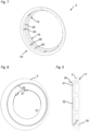
- the stop ring 3 In order to fasten the stop ring 3 securely to the compression sleeve 4 before the compression sleeve 4 is mounted on the fitting body 2, the stop ring 3 has an inner contour 14 on the sleeve side, which is used to produce a clamping connection.
- the inner contour 14 has a total of eight protruding, first regions 15 in the exemplary embodiment shown. In between there are eight second regions 16 that are receding in comparison thereto.
- the stop ring 3 can deform slightly when pushed onto the first axial end 9 of the compression sleeve 4 .
- the first areas 15 in particular produce a press fit.
- a first inner diameter d 1 of a remaining clear area between the first areas 15 is dimensioned such that it is smaller than an in figure 6 shown outer diameter d 3 of the compression sleeve 4 plus a possible negative manufacturing tolerance.
- a compression sleeve for a pipe with a diameter of 25 mm can have a tolerance range of approximately 0.25 mm, ie approximately 1% of the nominal diameter.
- the first inner diameter d 1 between end faces of the first regions 15 is dimensioned such that even with a minimum permissible outer diameter of the compression sleeve 4, an overlap of 0.1 mm remains to provide a clamping force.
- a second inner diameter d 2 between two opposite, most receding parts of the second regions 16 is dimensioned so large that in any case a clearance between a lateral surface of the compression sleeve 4 and a corresponding second area 16 of the inner contour 14 of the stop ring 3 remains.
- a minimum clearance of 0.1 mm remains within the tolerance range in the case of a maximum outer diameter of the ferrule 4 and a maximum distance of 0.35 mm in the case of a minimum outer diameter of the ferrule 4.
- the first areas 15 are connected to the second areas 16 by transition areas 30 that are arcuate in cross section, in which the inner diameter of the stop ring 3 increases steadily.
- the advantage of this design is that the curved transition areas 30 are mechanically particularly stable.
- the protruding, first areas 15 are designed so wide that they do not dip completely into the slots 10 of the compression sleeve 4 when the stop ring 3 is installed.
- a first side 17 of the stop ring 3, which faces the pressing area 11 in the assembled state, has a first chamfer 18.
- the first chamfer 18 enables the connection ring 3 to be centered and easily attached to the first axial end 9 of the compression sleeve 3.
- an opposite second side 19 of the stop ring 3 which faces the central area 6 of the fitting body 2 in the mounted state, has an inner contour 20 on the fitting side with a second chamfer 21 .
- the second chamfer 21 serves, among other things, to center an assembly group, comprising the stop ring 3 and the compression sleeve 4, when it is assembled the fitting body 2.
- An arcuate outer contour 22 of the stop ring 3 connects the outer diameter of the first side 17 continuously with the outer diameter of the second side 19, so that there are no steps in the cross section.
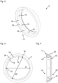
- the inner contour 14 on the sleeve side and the inner contour 20 on the fitting side are separated from one another by an inwardly protruding third projection, which at the same time forms an open bottom surface 23 of the inner contour 14 on the sleeve side and limits a maximum insertion depth of the compression sleeve 4 .
- the third projection or the open bottom surface 23 of the stop ring 3, as in the cross section figure 6 shown, fully or partially engage in the groove 7 of the fitting body 2. With appropriate dimensioning, it can also rest on a surface of the fitting body 2 outside of the groove 7 . In the exemplary embodiment, it limits the insertion depth of the assembly when the compression sleeve 4 is applied to the connection area 6a in that the second side 19 of the stop ring 3 abuts against an end face 35 of the central area 5 .
- figure 7 shows an alternative embodiment of a sleeve-side inner contour 14 of a stop ring 3.
- Deviating from the stop ring 3 according to the Figures 1 to 4 includes the inner contour 14 according to figure 7 an essentially cylindrical inner surface 24 and webs 25 arranged thereon.
- the intermediate sections of the cylindrical inner surface 24 form the second regions 16.
- the inner contour 20 on the fitting side has a protruding element 26 which is arranged in a relatively small circular segment 27 of the stop ring 3 .
- the stop ring 3 has a constant cross section.
- protruding means that a surface of the element 26 pointing towards the center of the stop ring 3 protrudes beyond a surrounding surface of the inner contour 20 on the fitting side or the constant cross section in the circle segment 31 .
- the element 26, as in the figure 10 shown, as a radially from the inner circumference of the stop ring 3, so perpendicular to its axis of symmetry inwardly projecting tab 33 may be formed.
- an inwardly inclined surface of the insertion bevel 32 in the region of the smaller circular segment 27 in which the element 26 is formed is either shifted inwards parallel to a surface of the chamfer 21 or has a greater inclination in the insertion direction than the second Chamfer 21 of the fitting-side inner contour 20.
- the element 26 serves in particular to lead to a relative tilting of the axes when the compression sleeve 4 with the connection ring 3 placed thereon is placed on a connection area 6 of the fitting body 2 .
- an assembly group 28 comprising the compression sleeve 4 and the connection ring 3, stands upright and with its first axial end 9 pointing upwards on a flat surface, such as a holding device of a machine tool.
- a fitting body 2 with a connection area 6 pointing downwards is then introduced essentially perpendicularly from above into the opening of the assembly group 28 .
- the axis directions of the assembly group 28 and the fitting body 2 initially match.
- connection body 2 can be tilted by approximately 2 to 5°.
- the assembly forces for a press fitting 1 for a nominal pipe diameter of 25 mm could be reduced to a press-in force of 242 N compared to a press-in force of approximately 2100 N with a coaxial press-in by inserting the connection area 6 into the assembly group 28 in an offset or tilted manner, which the assembly of the press fitting 1 considerably easier.
- the press-in force is reduced from 1500 N to 314 N. This reduction in the forces occurring during assembly has the additional advantage that damage to the fitting body 2 can be avoided, especially when using plastic materials for the fitting body 2 .
- the compression sleeve 4 and the fitting body 2 align themselves coaxially again.
- the offset or tilted application of the assembly group 28 does not have a negative effect on its alignment or on the secure attachment of the compression sleeve 4 to the fitting body 2 .
- figure 11 shows schematically the steps of a method for assembling a press fitting 1.
- a compression sleeve 4 with a predetermined nominal diameter is provided.
- This diameter can vary by a specific negative and/or positive tolerance value within a specified tolerance range.
- the compression sleeve 4 has one or more highlights, such as in particular lips 8 for direct locking with a fitting body 2 .
- a stop ring 3 is slipped onto the compression sleeve 4 at a first axial end 9.
- This is preferably fastened to the compression sleeve 4 , for example by providing raised first areas 15 and recessed, second areas 16 which result in the stop ring 3 jamming on the compression sleeve 4 .
- other connections in particular form-fitting connections, are also possible.
- step S3 the assembly group 28 of the compression sleeve 4 produced in this way, with the stop ring 3 attached thereto, is applied to a connection area 6 of a fitting body 2.
- This can be done, for example, by an industrial pick-and-place machine.
- a step S4 the longitudinal axes of the fitting body 2 and the assembly group 28 are tilted relative to one another. This can be done, for example, by appropriate control of an automatic placement machine or a ram or, as previously based on the Figures 8 to 10 described, can be ensured by providing a corresponding inner contour 20 on the fitting side with an outstanding element 26 .
- step S5 the assembly group 28 is then pushed or pressed further onto the fitting body 2, the compression sleeve 4 latches with the fitting body 2, for example by lips 8 engaging in a corresponding groove 7 of the fitting body 2.
- the stop ring 3 remains intact during the actual pressing of the compression sleeve 4 with a pipe end, since the pressing tool does not exert any force on the stop ring 3 in a radial pressing direction.
- the press fitting 1 described can be provided, for example, with a tubular banderole as a pressing mark.
- the sleeve-side inner contour 14 described above on the side of the stop ring 3 facing the pressing area 11 and the fitting-side inner contour 20 on the side of the stop ring 3 facing the fitting body 2 can be combined with one another as previously described.
- each of the inner contours 14 and 20 also brings about the effects and advantages described on its own and can therefore also be realized individually.
Landscapes
- Engineering & Computer Science (AREA)
- General Engineering & Computer Science (AREA)
- Mechanical Engineering (AREA)
- Automatic Assembly (AREA)
- Mutual Connection Of Rods And Tubes (AREA)
- Mechanical Coupling Of Light Guides (AREA)
Applications Claiming Priority (1)
| Application Number | Priority Date | Filing Date | Title |
|---|---|---|---|
| DE102021126520.7A DE102021126520A1 (de) | 2021-10-13 | 2021-10-13 | Montagegruppe für ein Pressfitting, Pressfitting und Montageverfahren für ein Pressfitting |
Publications (2)
| Publication Number | Publication Date |
|---|---|
| EP4166834A1 true EP4166834A1 (fr) | 2023-04-19 |
| EP4166834B1 EP4166834B1 (fr) | 2025-01-15 |
Family
ID=83691642
Family Applications (1)
| Application Number | Title | Priority Date | Filing Date |
|---|---|---|---|
| EP22201011.8A Active EP4166834B1 (fr) | 2021-10-13 | 2022-10-12 | Groupe de montage pour raccord à sertir, raccord à sertir et procédé de montage pour raccord à sertir |
Country Status (10)
| Country | Link |
|---|---|
| US (1) | US11940063B2 (fr) |
| EP (1) | EP4166834B1 (fr) |
| CA (1) | CA3178907A1 (fr) |
| DE (1) | DE102021126520A1 (fr) |
| DK (1) | DK4166834T3 (fr) |
| ES (1) | ES3009511T3 (fr) |
| FI (1) | FI4166834T3 (fr) |
| LT (1) | LT4166834T (fr) |
| PL (1) | PL4166834T3 (fr) |
| PT (1) | PT4166834T (fr) |
Citations (6)
| Publication number | Priority date | Publication date | Assignee | Title |
|---|---|---|---|---|
| EP1306601A2 (fr) * | 2001-10-26 | 2003-05-02 | Uponor Innovation Ab | Raccords à compression pour la connection d'au moins un tuyau |
| EP1790896A1 (fr) | 2005-11-24 | 2007-05-30 | Uponor Innovation Ab | Raccord à sertir pour un tuyau |
| EP1933073A1 (fr) * | 2006-12-12 | 2008-06-18 | Uponor Innovation Ab | Raccord de sertissage pour un tuyau |
| DE102018109555B3 (de) | 2018-04-20 | 2019-10-24 | Uponor Innovation Ab | Pressfitting für eine Rohrverbindung und Verfahren zu seiner Herstellung |
| EP3645926B1 (fr) * | 2017-06-27 | 2021-04-07 | Fränkische Rohrwerke Gebr. Kirchner GmbH & Co. KG | Manchon de sertissage |
| US11092265B2 (en) * | 2017-03-15 | 2021-08-17 | Viega Technology Gmbh & Co. Kg | Fitting to be connected to at least one pipe and method for establishing a connection |
Family Cites Families (8)
| Publication number | Priority date | Publication date | Assignee | Title |
|---|---|---|---|---|
| DE19542463B4 (de) | 1995-11-15 | 2004-05-27 | J. Van Walraven B.V. | Rohrkupplung |
| DE20207313U1 (de) | 2002-05-10 | 2003-09-18 | Franz Viegener II GmbH & Co. KG, 57439 Attendorn | Verbindungsstück und Verbindungsanordnung |
| DE102005028558B3 (de) * | 2005-06-21 | 2007-01-04 | Uponor Innovation Ab | Pressfitting für ein Rohr |
| CN200943796Y (zh) | 2006-09-14 | 2007-09-05 | 佛山市日丰企业有限公司 | 一种卡压式管件 |
| DE102008010084B4 (de) * | 2008-02-19 | 2016-12-29 | Viega Gmbh & Co. Kg | Übertragungselement für axial zu verpressende Werkstückverbindungen sowie Anordnung zur Herstellung einer unlösbaren Verbindung |
| WO2012069584A2 (fr) | 2010-11-24 | 2012-05-31 | Aliaxis R&D Sas | Emmanchement à la presse |
| NL1041958B1 (en) * | 2016-06-29 | 2018-01-05 | Wavin Bv | Press fitting device |
| US20190186664A1 (en) * | 2017-12-15 | 2019-06-20 | Gates Corporation | Hose coupling assembly |
-
2021
- 2021-10-13 DE DE102021126520.7A patent/DE102021126520A1/de active Pending
-
2022
- 2022-10-11 CA CA3178907A patent/CA3178907A1/fr active Pending
- 2022-10-12 EP EP22201011.8A patent/EP4166834B1/fr active Active
- 2022-10-12 PT PT222010118T patent/PT4166834T/pt unknown
- 2022-10-12 LT LTEP22201011.8T patent/LT4166834T/lt unknown
- 2022-10-12 DK DK22201011.8T patent/DK4166834T3/da active
- 2022-10-12 FI FIEP22201011.8T patent/FI4166834T3/en active
- 2022-10-12 PL PL22201011.8T patent/PL4166834T3/pl unknown
- 2022-10-12 ES ES22201011T patent/ES3009511T3/es active Active
- 2022-10-12 US US17/964,813 patent/US11940063B2/en active Active
Patent Citations (6)
| Publication number | Priority date | Publication date | Assignee | Title |
|---|---|---|---|---|
| EP1306601A2 (fr) * | 2001-10-26 | 2003-05-02 | Uponor Innovation Ab | Raccords à compression pour la connection d'au moins un tuyau |
| EP1790896A1 (fr) | 2005-11-24 | 2007-05-30 | Uponor Innovation Ab | Raccord à sertir pour un tuyau |
| EP1933073A1 (fr) * | 2006-12-12 | 2008-06-18 | Uponor Innovation Ab | Raccord de sertissage pour un tuyau |
| US11092265B2 (en) * | 2017-03-15 | 2021-08-17 | Viega Technology Gmbh & Co. Kg | Fitting to be connected to at least one pipe and method for establishing a connection |
| EP3645926B1 (fr) * | 2017-06-27 | 2021-04-07 | Fränkische Rohrwerke Gebr. Kirchner GmbH & Co. KG | Manchon de sertissage |
| DE102018109555B3 (de) | 2018-04-20 | 2019-10-24 | Uponor Innovation Ab | Pressfitting für eine Rohrverbindung und Verfahren zu seiner Herstellung |
Also Published As
| Publication number | Publication date |
|---|---|
| FI4166834T3 (en) | 2025-02-20 |
| US11940063B2 (en) | 2024-03-26 |
| US20230113248A1 (en) | 2023-04-13 |
| PT4166834T (pt) | 2025-01-30 |
| CA3178907A1 (fr) | 2023-04-13 |
| LT4166834T (lt) | 2025-02-10 |
| DK4166834T3 (da) | 2025-02-10 |
| PL4166834T3 (pl) | 2025-06-09 |
| DE102021126520A1 (de) | 2023-04-13 |
| ES3009511T3 (en) | 2025-03-27 |
| EP4166834B1 (fr) | 2025-01-15 |
Similar Documents
| Publication | Publication Date | Title |
|---|---|---|
| EP4166835A1 (fr) | Raccord à sertir pour raccord de tuyau et groupe de montage pour raccord à sertir | |
| DE4127961C2 (de) | Schnellkupplung | |
| DE69821063T2 (de) | Steckrohrverbindung | |
| EP2433119A1 (fr) | Unité d'enfichage et système de liaison permettant la liaison de capillaires, notamment en chromatographie en phase liquide à hautes performances | |
| EP3596377A1 (fr) | Pièce de raccordement destinée à être reliée à au moins un tube et procédé de réalisation d'un assemblage | |
| DE102009022859A1 (de) | Steckverbindung für Rohrleitungen | |
| WO1999051886A1 (fr) | Dispositif d'assemblage pour la jonction de deux composants, combinaison du dispositif d'assemblage avec les deux composants et procede d'obtention d'une jonction entre deux composants | |
| DE102008059897A1 (de) | Steckereinheit und Verbindungssystem für das Verbinden von Kapillaren, insbesondere für die Hochleistungsflüssigkeitschromatographie | |
| DE102012110991A1 (de) | Steckereinheit und Verbindungssystem zum Verbinden von Kapillaren, insbesondere für die Hochleistungsflüssigkeitschromatographie | |
| DE2756228B2 (de) | Kugelgelenkhalterungseinrichtung zum Festlegen eines Kugelgelenks in einem von zwei durch das Kugelgelenk zu verbindenden Bauteilen, Verfahren zum Festlegen eines Kugelgelenks in einem von zwei durch das Kugelgelenk zu verbindenen Bauteilen, Vorrichtung zum Verstemmen eines Kugelgelenks in einem von zwei durch das Kugelgelenk zu verbindenden Bauteilen und Verfahren zum Festlegen eines Kugelgelenks in einem von zwei durch das Kugelgelenk zu verbindenden Bauteilen | |
| EP3645926B1 (fr) | Manchon de sertissage | |
| DE60115413T2 (de) | Fitting für eine druckmittelkupplung für kunststoffrohre | |
| EP2193303A1 (fr) | Raccord à presser pour un tube, notamment pour un tube plastique ou tuyau composite constitué de plastique et de métal | |
| EP4158233B1 (fr) | Fiche de connexion et ensemble fiche formé à partir de celle-ci | |
| EP1907742B1 (fr) | Tuyau souple et procede pour monter un ecrou d'accouplement sur un tuyau souple | |
| EP2002166B1 (fr) | Dispositif de liaison | |
| EP4166834A1 (fr) | Groupe de montage pour raccord à sertir, raccord à sertir et procédé de montage pour raccord à sertir | |
| DE69626500T2 (de) | Rohranschluss | |
| EP1770320B1 (fr) | Raccord détachable à fiche pour des tuyaux | |
| WO2012031671A1 (fr) | Procédé de mise en place d'une douille, en particulier d'une douille filetée dans une pièce | |
| AT525084B1 (de) | Rohrpresskupplung | |
| EP0427989B1 (fr) | Procédé pour obturer et ouvrir un tuyau | |
| AT526773B1 (de) | Steckhülse und Verbindungshülse mit Steckhülse | |
| DE102008053380A1 (de) | Verbindung | |
| EP1729371A1 (fr) | Douille et son procédé fabrication |
Legal Events
| Date | Code | Title | Description |
|---|---|---|---|
| PUAI | Public reference made under article 153(3) epc to a published international application that has entered the european phase |
Free format text: ORIGINAL CODE: 0009012 |
|
| STAA | Information on the status of an ep patent application or granted ep patent |
Free format text: STATUS: THE APPLICATION HAS BEEN PUBLISHED |
|
| AK | Designated contracting states |
Kind code of ref document: A1 Designated state(s): AL AT BE BG CH CY CZ DE DK EE ES FI FR GB GR HR HU IE IS IT LI LT LU LV MC ME MK MT NL NO PL PT RO RS SE SI SK SM TR |
|
| STAA | Information on the status of an ep patent application or granted ep patent |
Free format text: STATUS: REQUEST FOR EXAMINATION WAS MADE |
|
| 17P | Request for examination filed |
Effective date: 20230727 |
|
| RBV | Designated contracting states (corrected) |
Designated state(s): AL AT BE BG CH CY CZ DE DK EE ES FI FR GB GR HR HU IE IS IT LI LT LU LV MC ME MK MT NL NO PL PT RO RS SE SI SK SM TR |
|
| STAA | Information on the status of an ep patent application or granted ep patent |
Free format text: STATUS: EXAMINATION IS IN PROGRESS |
|
| 17Q | First examination report despatched |
Effective date: 20240411 |
|
| GRAP | Despatch of communication of intention to grant a patent |
Free format text: ORIGINAL CODE: EPIDOSNIGR1 |
|
| STAA | Information on the status of an ep patent application or granted ep patent |
Free format text: STATUS: GRANT OF PATENT IS INTENDED |
|
| INTG | Intention to grant announced |
Effective date: 20240808 |
|
| GRAS | Grant fee paid |
Free format text: ORIGINAL CODE: EPIDOSNIGR3 |
|
| GRAA | (expected) grant |
Free format text: ORIGINAL CODE: 0009210 |
|
| STAA | Information on the status of an ep patent application or granted ep patent |
Free format text: STATUS: THE PATENT HAS BEEN GRANTED |
|
| P01 | Opt-out of the competence of the unified patent court (upc) registered |
Free format text: CASE NUMBER: APP_60770/2024 Effective date: 20241112 |
|
| AK | Designated contracting states |
Kind code of ref document: B1 Designated state(s): AL AT BE BG CH CY CZ DE DK EE ES FI FR GB GR HR HU IE IS IT LI LT LU LV MC ME MK MT NL NO PL PT RO RS SE SI SK SM TR |
|
| REG | Reference to a national code |
Ref country code: CH Ref legal event code: EP Ref country code: GB Ref legal event code: FG4D Free format text: NOT ENGLISH |
|
| REG | Reference to a national code |
Ref country code: PT Ref legal event code: SC4A Ref document number: 4166834 Country of ref document: PT Date of ref document: 20250130 Kind code of ref document: T Free format text: AVAILABILITY OF NATIONAL TRANSLATION Effective date: 20250124 Ref country code: DE Ref legal event code: R096 Ref document number: 502022002629 Country of ref document: DE |
|
| REG | Reference to a national code |
Ref country code: DK Ref legal event code: T3 Effective date: 20250206 |
|
| REG | Reference to a national code |
Ref country code: IE Ref legal event code: FG4D Free format text: LANGUAGE OF EP DOCUMENT: GERMAN |
|
| REG | Reference to a national code |
Ref country code: FI Ref legal event code: FGE |
|
| REG | Reference to a national code |
Ref country code: NL Ref legal event code: FP |
|
| REG | Reference to a national code |
Ref country code: SE Ref legal event code: TRGR |
|
| REG | Reference to a national code |
Ref country code: ES Ref legal event code: FG2A Ref document number: 3009511 Country of ref document: ES Kind code of ref document: T3 Effective date: 20250327 |
|
| REG | Reference to a national code |
Ref country code: EE Ref legal event code: FG4A Ref document number: E025017 Country of ref document: EE Effective date: 20250311 |
|
| PG25 | Lapsed in a contracting state [announced via postgrant information from national office to epo] |
Ref country code: RS Free format text: LAPSE BECAUSE OF FAILURE TO SUBMIT A TRANSLATION OF THE DESCRIPTION OR TO PAY THE FEE WITHIN THE PRESCRIBED TIME-LIMIT Effective date: 20250415 |
|
| PG25 | Lapsed in a contracting state [announced via postgrant information from national office to epo] |
Ref country code: IS Free format text: LAPSE BECAUSE OF FAILURE TO SUBMIT A TRANSLATION OF THE DESCRIPTION OR TO PAY THE FEE WITHIN THE PRESCRIBED TIME-LIMIT Effective date: 20250515 |
|
| PG25 | Lapsed in a contracting state [announced via postgrant information from national office to epo] |
Ref country code: HR Free format text: LAPSE BECAUSE OF FAILURE TO SUBMIT A TRANSLATION OF THE DESCRIPTION OR TO PAY THE FEE WITHIN THE PRESCRIBED TIME-LIMIT Effective date: 20250115 |
|
| PG25 | Lapsed in a contracting state [announced via postgrant information from national office to epo] |
Ref country code: LV Free format text: LAPSE BECAUSE OF FAILURE TO SUBMIT A TRANSLATION OF THE DESCRIPTION OR TO PAY THE FEE WITHIN THE PRESCRIBED TIME-LIMIT Effective date: 20250115 |
|
| PG25 | Lapsed in a contracting state [announced via postgrant information from national office to epo] |
Ref country code: GR Free format text: LAPSE BECAUSE OF FAILURE TO SUBMIT A TRANSLATION OF THE DESCRIPTION OR TO PAY THE FEE WITHIN THE PRESCRIBED TIME-LIMIT Effective date: 20250416 |
|
| PG25 | Lapsed in a contracting state [announced via postgrant information from national office to epo] |
Ref country code: SM Free format text: LAPSE BECAUSE OF FAILURE TO SUBMIT A TRANSLATION OF THE DESCRIPTION OR TO PAY THE FEE WITHIN THE PRESCRIBED TIME-LIMIT Effective date: 20250115 |
|
| REG | Reference to a national code |
Ref country code: DE Ref legal event code: R097 Ref document number: 502022002629 Country of ref document: DE |
|
| PG25 | Lapsed in a contracting state [announced via postgrant information from national office to epo] |
Ref country code: SK Free format text: LAPSE BECAUSE OF FAILURE TO SUBMIT A TRANSLATION OF THE DESCRIPTION OR TO PAY THE FEE WITHIN THE PRESCRIBED TIME-LIMIT Effective date: 20250115 |
|
| PGFP | Annual fee paid to national office [announced via postgrant information from national office to epo] |
Ref country code: NL Payment date: 20251021 Year of fee payment: 4 |
|
| PLBE | No opposition filed within time limit |
Free format text: ORIGINAL CODE: 0009261 |
|
| STAA | Information on the status of an ep patent application or granted ep patent |
Free format text: STATUS: NO OPPOSITION FILED WITHIN TIME LIMIT |
|
| PGFP | Annual fee paid to national office [announced via postgrant information from national office to epo] |
Ref country code: PT Payment date: 20251002 Year of fee payment: 4 |
|
| 26N | No opposition filed |
Effective date: 20251016 |
|
| PGFP | Annual fee paid to national office [announced via postgrant information from national office to epo] |
Ref country code: DE Payment date: 20251021 Year of fee payment: 4 |
|
| PGFP | Annual fee paid to national office [announced via postgrant information from national office to epo] |
Ref country code: LT Payment date: 20250929 Year of fee payment: 4 |
|
| PGFP | Annual fee paid to national office [announced via postgrant information from national office to epo] |
Ref country code: NO Payment date: 20251024 Year of fee payment: 4 |
|
| PGFP | Annual fee paid to national office [announced via postgrant information from national office to epo] |
Ref country code: AT Payment date: 20260113 Year of fee payment: 4 |
|
| PGFP | Annual fee paid to national office [announced via postgrant information from national office to epo] |
Ref country code: FI Payment date: 20251028 Year of fee payment: 4 Ref country code: DK Payment date: 20251027 Year of fee payment: 4 Ref country code: IT Payment date: 20251031 Year of fee payment: 4 |
|
| PGFP | Annual fee paid to national office [announced via postgrant information from national office to epo] |
Ref country code: FR Payment date: 20251030 Year of fee payment: 4 |
|
| PGFP | Annual fee paid to national office [announced via postgrant information from national office to epo] |
Ref country code: SE Payment date: 20251021 Year of fee payment: 4 |
|
| PGFP | Annual fee paid to national office [announced via postgrant information from national office to epo] |
Ref country code: CZ Payment date: 20251009 Year of fee payment: 4 |
|
| PGFP | Annual fee paid to national office [announced via postgrant information from national office to epo] |
Ref country code: BG Payment date: 20251023 Year of fee payment: 4 Ref country code: PL Payment date: 20251003 Year of fee payment: 4 |
|
| PGFP | Annual fee paid to national office [announced via postgrant information from national office to epo] |
Ref country code: EE Payment date: 20251106 Year of fee payment: 4 |
|
| PGFP | Annual fee paid to national office [announced via postgrant information from national office to epo] |
Ref country code: RO Payment date: 20251003 Year of fee payment: 4 |
|
| PGFP | Annual fee paid to national office [announced via postgrant information from national office to epo] |
Ref country code: ES Payment date: 20251216 Year of fee payment: 4 |