EP4166854A1 - Augmentation de la solubilité d'alcanes - Google Patents
Augmentation de la solubilité d'alcanes Download PDFInfo
- Publication number
- EP4166854A1 EP4166854A1 EP22202147.9A EP22202147A EP4166854A1 EP 4166854 A1 EP4166854 A1 EP 4166854A1 EP 22202147 A EP22202147 A EP 22202147A EP 4166854 A1 EP4166854 A1 EP 4166854A1
- Authority
- EP
- European Patent Office
- Prior art keywords
- heat transfer
- transfer fluid
- heat
- refrigerant
- circulating pump
- Prior art date
- Legal status (The legal status is an assumption and is not a legal conclusion. Google has not performed a legal analysis and makes no representation as to the accuracy of the status listed.)
- Granted
Links
Images
Classifications
-
- F—MECHANICAL ENGINEERING; LIGHTING; HEATING; WEAPONS; BLASTING
- F24—HEATING; RANGES; VENTILATING
- F24D—DOMESTIC- OR SPACE-HEATING SYSTEMS, e.g. CENTRAL HEATING SYSTEMS; DOMESTIC HOT-WATER SUPPLY SYSTEMS; ELEMENTS OR COMPONENTS THEREFOR
- F24D3/00—Hot-water central heating systems
- F24D3/18—Hot-water central heating systems using heat pumps
-
- F—MECHANICAL ENGINEERING; LIGHTING; HEATING; WEAPONS; BLASTING
- F24—HEATING; RANGES; VENTILATING
- F24D—DOMESTIC- OR SPACE-HEATING SYSTEMS, e.g. CENTRAL HEATING SYSTEMS; DOMESTIC HOT-WATER SUPPLY SYSTEMS; ELEMENTS OR COMPONENTS THEREFOR
- F24D19/00—Details
- F24D19/08—Arrangements for drainage, venting or aerating
- F24D19/082—Arrangements for drainage, venting or aerating for water heating systems
- F24D19/083—Venting arrangements
-
- F—MECHANICAL ENGINEERING; LIGHTING; HEATING; WEAPONS; BLASTING
- F24—HEATING; RANGES; VENTILATING
- F24D—DOMESTIC- OR SPACE-HEATING SYSTEMS, e.g. CENTRAL HEATING SYSTEMS; DOMESTIC HOT-WATER SUPPLY SYSTEMS; ELEMENTS OR COMPONENTS THEREFOR
- F24D19/00—Details
- F24D19/10—Arrangement or mounting of control or safety devices
- F24D19/1006—Arrangement or mounting of control or safety devices for water heating systems
- F24D19/1009—Arrangement or mounting of control or safety devices for water heating systems for central heating
- F24D19/1039—Arrangement or mounting of control or safety devices for water heating systems for central heating the system uses a heat pump
-
- F—MECHANICAL ENGINEERING; LIGHTING; HEATING; WEAPONS; BLASTING
- F24—HEATING; RANGES; VENTILATING
- F24H—FLUID HEATERS, e.g. WATER OR AIR HEATERS, HAVING HEAT-GENERATING MEANS, e.g. HEAT PUMPS, IN GENERAL
- F24H15/00—Control of fluid heaters
- F24H15/10—Control of fluid heaters characterised by the purpose of the control
- F24H15/12—Preventing or detecting fluid leakage
Definitions
- the invention relates to the rendering harmless of flammable gases containing refrigerant in a brine circuit, referred to below as the heat transfer fluid circuit, of a heat pump system.
- heating circuits occasionally have to be vented because air can collect in the system. This usually happens due to leaks at elevated points in the heating circuit, where a leak in connection with negative pressure leads to air being sucked into the water circuit. In some cases, it is also air that is dissolved in top-up water and is released when it is heated.
- brine-split systems in which brine is in the heating circuit or in an outdoor box or in a geothermal probe, and also for air conditioning systems.
- additives are added to the heat transfer fluid circuit in addition to the actual heat transfer medium, usually water. These are usually antifreeze or anti-corrosion agents.
- flammable refrigerants are now used as working fluids in heat pumps and in cooling and freezing systems, which have the advantage of not damaging either the climate or the ozone layer if they are accidentally released.
- due to their flammability such an accidental release should be avoided as far as possible.
- the heat exchangers which act as condensers and evaporators are used and which are connected to the heat transfer fluid circuit, i.e. the heating circuit or cooling brine circuit, via their exchange surfaces.
- the working fluid in the refrigeration circuit is under a higher pressure than the heat transfer fluid in the heating circuit or cooling brine circuit, so it could easily get into the heat transfer fluid circuit, which is under lower pressure, in the event of leaks.
- double-walled heat exchangers are used in the conventional prior art, such as those described in the patent specifications DE 11 2019 001 344 T5 , DE 11 2019 001 350 T5 and DE 11 2019 001 351 T5 are described for heat pumps that lead the working fluid R290 to a water-propylene glycol brine as the heat transfer fluid.
- this use leads to a loss of efficiency, since the materials, such as stainless steel, conduct heat poorly and the thin air gap between the heat transfer surfaces acts as insulation. In practice, this means that higher temperature differences have to be set in the heat exchangers, which reduces the efficiency of heat pumps.
- these double-walled heat exchangers can reduce the risk, they cannot eliminate it.
- Propylene glycol is preferably added as an antifreeze to aqueous heat transfer fluid circuits. This has the advantage that it can be mixed with water as desired and in case from accidents is non-toxic to people and the environment.
- An advantage of this antifreeze is that the solubility of R290 and other alkanes increases significantly.
- Ethylene glycol is also commonly used.
- a corrosion inhibitor is usually used to prevent corrosion.
- Modern heat pumps can also be designed to be switchable between heating and air conditioning and can also produce hot water. This further increases the temperature changes occurring in the system. Further problems can arise from the fact that many heat pumps are not in operation all year round, but leaks can also occur outside of operation, for example if the brine in a solar thermal system heats up too much.
- alkanes are non-polar, non-polar but water-soluble substances are added to the heating brine or heating water. These result in the dissolution behavior being significantly improved and, if they get from the working fluid circuit into the heat transfer fluid circuit due to leakage, they no longer have to be separated out as gas bubbles. However, it must be ensured that the working fluid that has escaped can be dissolved in the heat transfer fluid under all circumstances.
- solubility-improving substances should be as uncomplicated as the addition of conventional corrosion inhibitors, preferably only every few years as part of maintenance work.
- the dissolving power should preferably be so good that continued operation after the leak has been repaired without replacing the heat transfer fluid.
- the object of the invention is therefore to ensure that gaseous alkane-containing working fluid components can be reliably dissolved in the heat transfer fluid and remain dissolved in the heat transfer fluid.
- the invention solves the problem by additives in the heat transfer fluid in connection with a mixing process and a mixing station.
- the invention solves the problem with an additive for increasing the solubility of alkanes dissolved in heat transfer fluid, the heat transfer fluid being a mixture of water, antifreeze and corrosion inhibitors, the additive being at least one water-soluble hydrocarbon compound.
- the medium-length, water-soluble hydrocarbon compound is selected from a group consisting of alcohols, alkanoic acids, fatty acids, fats, aldehydes and ketones.
- This is preferably either ethanol or a soap or a sugar compound or mixtures thereof.
- it can also be a medium-chain ionic liquid.
- coated nanoparticles, on the surface of which alkanes are adsorbed, can be added.
- the problem with a larger crack and a rapid escape of working fluid is that the heat transfer fluid is displaced over long distances by the gaseous working fluid, since the working fluid is usually under significantly higher pressure than the heat transfer fluid.
- This displacement means, on the one hand, that the heat transfer fluid cannot develop its dissolving effect and, on the other hand, that conventional conveying devices such as high-efficiency circulating pumps run dry and are damaged, but also that they can no longer convey heat transfer fluid, so-called gas bags occur.
- the gas bags can no longer be safely removed from the heat transfer fluid circuit if the flow collapses, and only a small amount of the alkane-containing gas in the heat transfer fluid would be able to be released.
- a mixing station which causes gaseous working fluid in the heat transfer fluid to be brought into contact with a sufficient amount of heat transfer fluid to dissolve it before it can get into the brine circuit.
- the circulating pumps for the heat transfer fluid are arranged on the inflow side of the respective heat exchanger. To ensure, that in the event of a leak, the working fluid cannot push the heat transfer fluid through the circulating pump in the opposite direction to the intended flow direction and reach the circulating pump in this way, the circulating pump is secured by a non-return valve.
- a closed reservoir for heat transfer fluid is arranged on the outflow side of the respective heat exchanger.
- Such reservoirs are often used anyway for temporary storage of heat transfer fluid; if so, such a container can be used.
- Heat transfer fluid constantly flows through it during operation.
- a float which, in the event of a gas leak, sends a signal to a circulating pump as it sinks.
- This circulating pump has forced delivery, for example Roots pumps or peristaltic pumps are suitable, and carries out pumping through the reservoir.
- a static mixer is run through.
- the addition to the reservoir can be done, for example, by a spray device in the top area of the container.
- the heat transfer fluid circuit can initially continue to be operated until the defective heat exchanger has been replaced or repaired.
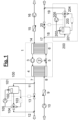
- the heat pump 1 shows a process flow diagram with one mixing device for each heat exchanger.
- the heat pump 1 has a counterclockwise cyclic process 2 with a compressor 3 , a condenser 4 , an expansion valve 5 and an evaporator 6 .
- the heat transfer fluid 7 is drawn off from the condenser 4 and fed into the mixing station 100 via the connecting line 11 .
- the mixing container 101 which is usually completely filled with heat transfer fluid.
- the float switch 102 indicates that there is no gas or that it is not accumulating in the upper area of the mixing container. If there are traces of working fluid in the heat transfer fluid, they would dissolve in the mixing container.
- the heat transfer fluid can therefore be fed to the heating circuit via the valve 104 and the connecting line 12 as heated heat transfer fluid. After the heat has been released, it is fed back into the return flow 8 of the condenser 4 by the circulating pump 10 and the non-return valve 9 .
- the float switch 102 triggers a signal which sets the circulating pump 105 with forced delivery in motion.
- the gas-liquid mixture is fed from the mixing tank into the static mixer 103 and the connection to the circulating pump 105 is activated in the valve 104 , while the distribution valve 104 blocks the inflow into the connecting line 12 .
- the path into the heating circuit can be opened again via the valve 104 .
- the shut-off valve 13 serves only as a safety measure and can remain closed during the entire mixing process. Only in special cases, when there is already gas in the heating circuit, can the shut-off valve 13 be opened and a backflow into the connecting line 11 can take place with subsequent mixing in the Mixing station 100. This makes sense above all if the mixing station 100 is used as a mobile station, which is only connected when there are other indications that there is undissolved working fluid in the heating circuit.
- the mixing station 200 corresponds to the mixing station 100.
- the circulating pump 16 conveys heat transfer fluid via the non-return valve 15 into the inflow 14 of the evaporator 6, where the heat transfer fluid leaves via the outflow 17 and is fed into the mixing station 200 via the connecting line 18.
- the float switch 202 indicates that there is no gas or that it is not accumulating in the upper area of the mixing container.
- the static mixer 203 corresponds to the static mixer 103, the distribution valve 204 to the distribution valve 104, the circulating pump 205 to the circulating pump 105, each with forced delivery, the connecting line 19 to the connecting line 12, the shut-off valve 20 to the shut-off valve 13.
Landscapes
- Engineering & Computer Science (AREA)
- Physics & Mathematics (AREA)
- Thermal Sciences (AREA)
- Chemical & Material Sciences (AREA)
- Combustion & Propulsion (AREA)
- Mechanical Engineering (AREA)
- General Engineering & Computer Science (AREA)
- Other Air-Conditioning Systems (AREA)
Applications Claiming Priority (1)
| Application Number | Priority Date | Filing Date | Title |
|---|---|---|---|
| DE102021126948.2A DE102021126948A1 (de) | 2021-10-18 | 2021-10-18 | Löslichkeitserhöhung von Alkanen |
Publications (3)
| Publication Number | Publication Date |
|---|---|
| EP4166854A1 true EP4166854A1 (fr) | 2023-04-19 |
| EP4166854B1 EP4166854B1 (fr) | 2025-10-08 |
| EP4166854C0 EP4166854C0 (fr) | 2025-10-08 |
Family
ID=83903049
Family Applications (1)
| Application Number | Title | Priority Date | Filing Date |
|---|---|---|---|
| EP22202147.9A Active EP4166854B1 (fr) | 2021-10-18 | 2022-10-18 | Augmentation de la solubilité d'alcanes |
Country Status (2)
| Country | Link |
|---|---|
| EP (1) | EP4166854B1 (fr) |
| DE (1) | DE102021126948A1 (fr) |
Cited By (1)
| Publication number | Priority date | Publication date | Assignee | Title |
|---|---|---|---|---|
| EP4559552A1 (fr) | 2023-11-21 | 2025-05-28 | Vaillant GmbH | Séparateur cyclone gaz-liquide |
Families Citing this family (1)
| Publication number | Priority date | Publication date | Assignee | Title |
|---|---|---|---|---|
| DE102023110401A1 (de) | 2023-04-24 | 2024-10-24 | Kresimir Strlek | Energiesystem |
Citations (7)
| Publication number | Priority date | Publication date | Assignee | Title |
|---|---|---|---|---|
| EP0897417B1 (fr) | 1996-05-07 | 2001-10-24 | Linde Aktiengesellschaft | Solution aqueuse de formiate de potassium/carbonate de potassium |
| EP3351868A1 (fr) * | 2016-12-09 | 2018-07-25 | Mitsubishi Electric Corporation | Dispositif de pompe à chaleur |
| DE112019001350T5 (de) | 2018-03-15 | 2020-12-03 | Mitsubishi Electric Corporation | Plattenwärmetauscher und diesen enthaltende Wärmepumpenvorrichtung |
| DE112019001351T5 (de) | 2018-03-15 | 2020-12-03 | Mitsubishi Electric Corporation | Plattenwärmetauscher, wärmepumpengerät einschliesslichplattenwärmetauscher, und wärmepumpen-kühl-, heiz- undwarmwasserversorgungssystem einschliesslich wärmepumpengerät |
| DE112019001344T5 (de) | 2018-03-15 | 2020-12-03 | Mitsubishi Electric Corporation | Plattenwärmetauscher, wärmepumpengerät mit plattenwärmetauscher und wärmepumpentyp eines kühl-, heiz- und warmwasserversorgungssystems mit wärmepumpengerät |
| EP3764001A1 (fr) * | 2019-07-12 | 2021-01-13 | Vaillant GmbH | Procédé et dispositif de dégazage d'un liquide dans un circuit, en particulier dans un circuit de chauffage d'un système de pompe a chaleur |
| EP3882526A1 (fr) * | 2020-03-19 | 2021-09-22 | Vaillant GmbH | Phase de séparation |
Family Cites Families (6)
| Publication number | Priority date | Publication date | Assignee | Title |
|---|---|---|---|---|
| US5741436A (en) | 1995-12-05 | 1998-04-21 | Prestone Products Corp. | Antifreeze concentrates and compositions comprising neodecanoic acid corrosion inhibitors |
| JPH11158459A (ja) | 1997-11-25 | 1999-06-15 | Takei Seisakusho:Kk | 熱媒体 |
| US6984339B2 (en) | 2003-02-28 | 2006-01-10 | Apex Materials Corporation | Antifreeze composition |
| JP4362383B2 (ja) | 2004-02-02 | 2009-11-11 | 東京電力株式会社 | アンモニア冷凍装置用の除害装置 |
| JP7096810B2 (ja) | 2016-07-12 | 2022-07-06 | プレストーン プロダクツ コーポレイション | 熱伝達システムにおける腐食を抑制するための熱伝達流体及び方法 |
| EP3827472A1 (fr) | 2018-07-25 | 2021-06-02 | The Lubrizol Corporation | Système aqueux de transfert de chaleur et procédé de dispersion de chaleur à partir de composants électriques |
-
2021
- 2021-10-18 DE DE102021126948.2A patent/DE102021126948A1/de active Pending
-
2022
- 2022-10-18 EP EP22202147.9A patent/EP4166854B1/fr active Active
Patent Citations (7)
| Publication number | Priority date | Publication date | Assignee | Title |
|---|---|---|---|---|
| EP0897417B1 (fr) | 1996-05-07 | 2001-10-24 | Linde Aktiengesellschaft | Solution aqueuse de formiate de potassium/carbonate de potassium |
| EP3351868A1 (fr) * | 2016-12-09 | 2018-07-25 | Mitsubishi Electric Corporation | Dispositif de pompe à chaleur |
| DE112019001350T5 (de) | 2018-03-15 | 2020-12-03 | Mitsubishi Electric Corporation | Plattenwärmetauscher und diesen enthaltende Wärmepumpenvorrichtung |
| DE112019001351T5 (de) | 2018-03-15 | 2020-12-03 | Mitsubishi Electric Corporation | Plattenwärmetauscher, wärmepumpengerät einschliesslichplattenwärmetauscher, und wärmepumpen-kühl-, heiz- undwarmwasserversorgungssystem einschliesslich wärmepumpengerät |
| DE112019001344T5 (de) | 2018-03-15 | 2020-12-03 | Mitsubishi Electric Corporation | Plattenwärmetauscher, wärmepumpengerät mit plattenwärmetauscher und wärmepumpentyp eines kühl-, heiz- und warmwasserversorgungssystems mit wärmepumpengerät |
| EP3764001A1 (fr) * | 2019-07-12 | 2021-01-13 | Vaillant GmbH | Procédé et dispositif de dégazage d'un liquide dans un circuit, en particulier dans un circuit de chauffage d'un système de pompe a chaleur |
| EP3882526A1 (fr) * | 2020-03-19 | 2021-09-22 | Vaillant GmbH | Phase de séparation |
Cited By (1)
| Publication number | Priority date | Publication date | Assignee | Title |
|---|---|---|---|---|
| EP4559552A1 (fr) | 2023-11-21 | 2025-05-28 | Vaillant GmbH | Séparateur cyclone gaz-liquide |
Also Published As
| Publication number | Publication date |
|---|---|
| EP4166854B1 (fr) | 2025-10-08 |
| DE102021126948A1 (de) | 2023-04-20 |
| EP4166854C0 (fr) | 2025-10-08 |
Similar Documents
| Publication | Publication Date | Title |
|---|---|---|
| EP4212784A1 (fr) | Extraction liquide d'hydrocarbures | |
| EP4166854A1 (fr) | Augmentation de la solubilité d'alcanes | |
| EP3730861B1 (fr) | Dispositif de production d'eau chaude | |
| DE112014003256T5 (de) | Arbeitsfluid für einen Wärmekreisprozess, Zusammensetzung für ein Wärmekreisprozesssystem und Wärmekreisprozesssystem | |
| EP3882526B1 (fr) | Procede de separation et dispositif de separation | |
| DE112014001458T5 (de) | Schmierstoffentschäumerzusätze und -zusammensetzungen | |
| EP3789686A1 (fr) | Système de pompe à chaleur | |
| DE102011086476A1 (de) | Hochtemperaturwärmepumpe und Verfahren zur Verwendung eines Arbeitsmediums in einer Hochtemperaturwärmepumpe | |
| DE2827644A1 (de) | Verdichter fuer eine waermepumpe | |
| EP3767186A1 (fr) | Dispositif de sécurité d'une unité de pompe à chaleur | |
| WO2008058663A1 (fr) | Sonde géothermique | |
| CN110452674A (zh) | Co2驱注入井环空保护液及其制备方法 | |
| DE29824676U1 (de) | Wärmeübertrager | |
| DE2345380C3 (de) | Naß-Sprinkleranlage für große Tiefkühlhäuser | |
| DE102021126949A1 (de) | Löslichkeitsverringerung von Alkanen | |
| DE102010028950B4 (de) | Vorrichtung zum Kühlen und Rechner-Racks | |
| EP3767187B1 (fr) | Procédé de commande d'un ensemble de pompes à chaleur | |
| EP3936790B1 (fr) | Procédé de décomposition catalytique des alcanes | |
| EP4459201A1 (fr) | Gestion de fuites de gaz | |
| EP0766051A1 (fr) | Installation frigorifique | |
| CN1331978C (zh) | 一种钻井液用聚合醇润滑抑制剂及其应用 | |
| EP3879201A1 (fr) | Dispositif de stockage tampon souterrain ainsi que procédé de stockage tampon dans un support de moyen de stockage de chaleur | |
| DE102019119871A1 (de) | Vorrichtung und Verfahren zur Belüftung einer Wärmepumpe | |
| DE202012003480U1 (de) | Erdwärmesonde | |
| CN108865100A (zh) | 一种可重复利用降阻水体系 |
Legal Events
| Date | Code | Title | Description |
|---|---|---|---|
| PUAI | Public reference made under article 153(3) epc to a published international application that has entered the european phase |
Free format text: ORIGINAL CODE: 0009012 |
|
| STAA | Information on the status of an ep patent application or granted ep patent |
Free format text: STATUS: THE APPLICATION HAS BEEN PUBLISHED |
|
| AK | Designated contracting states |
Kind code of ref document: A1 Designated state(s): AL AT BE BG CH CY CZ DE DK EE ES FI FR GB GR HR HU IE IS IT LI LT LU LV MC ME MK MT NL NO PL PT RO RS SE SI SK SM TR |
|
| STAA | Information on the status of an ep patent application or granted ep patent |
Free format text: STATUS: REQUEST FOR EXAMINATION WAS MADE |
|
| 17P | Request for examination filed |
Effective date: 20231017 |
|
| RBV | Designated contracting states (corrected) |
Designated state(s): AL AT BE BG CH CY CZ DE DK EE ES FI FR GB GR HR HU IE IS IT LI LT LU LV MC ME MK MT NL NO PL PT RO RS SE SI SK SM TR |
|
| GRAP | Despatch of communication of intention to grant a patent |
Free format text: ORIGINAL CODE: EPIDOSNIGR1 |
|
| STAA | Information on the status of an ep patent application or granted ep patent |
Free format text: STATUS: GRANT OF PATENT IS INTENDED |
|
| INTG | Intention to grant announced |
Effective date: 20250512 |
|
| GRAS | Grant fee paid |
Free format text: ORIGINAL CODE: EPIDOSNIGR3 |
|
| GRAA | (expected) grant |
Free format text: ORIGINAL CODE: 0009210 |
|
| STAA | Information on the status of an ep patent application or granted ep patent |
Free format text: STATUS: THE PATENT HAS BEEN GRANTED |
|
| AK | Designated contracting states |
Kind code of ref document: B1 Designated state(s): AL AT BE BG CH CY CZ DE DK EE ES FI FR GB GR HR HU IE IS IT LI LT LU LV MC ME MK MT NL NO PL PT RO RS SE SI SK SM TR |
|
| REG | Reference to a national code |
Ref country code: GB Ref legal event code: FG4D Free format text: NOT ENGLISH Ref country code: CH Ref legal event code: F10 Free format text: ST27 STATUS EVENT CODE: U-0-0-F10-F00 (AS PROVIDED BY THE NATIONAL OFFICE) Effective date: 20251008 |
|
| REG | Reference to a national code |
Ref country code: DE Ref legal event code: R096 Ref document number: 502022005695 Country of ref document: DE |
|
| REG | Reference to a national code |
Ref country code: IE Ref legal event code: FG4D Free format text: LANGUAGE OF EP DOCUMENT: GERMAN |
|
| U01 | Request for unitary effect filed |
Effective date: 20251008 |
|
| U07 | Unitary effect registered |
Designated state(s): AT BE BG DE DK EE FI FR IT LT LU LV MT NL PT RO SE SI Effective date: 20251014 |
|
| U20 | Renewal fee for the european patent with unitary effect paid |
Year of fee payment: 4 Effective date: 20251014 |
|
| PG25 | Lapsed in a contracting state [announced via postgrant information from national office to epo] |
Ref country code: ES Free format text: LAPSE BECAUSE OF FAILURE TO SUBMIT A TRANSLATION OF THE DESCRIPTION OR TO PAY THE FEE WITHIN THE PRESCRIBED TIME-LIMIT Effective date: 20251008 |
|
| PG25 | Lapsed in a contracting state [announced via postgrant information from national office to epo] |
Ref country code: NO Free format text: LAPSE BECAUSE OF FAILURE TO SUBMIT A TRANSLATION OF THE DESCRIPTION OR TO PAY THE FEE WITHIN THE PRESCRIBED TIME-LIMIT Effective date: 20260108 |
|
| PG25 | Lapsed in a contracting state [announced via postgrant information from national office to epo] |
Ref country code: HR Free format text: LAPSE BECAUSE OF FAILURE TO SUBMIT A TRANSLATION OF THE DESCRIPTION OR TO PAY THE FEE WITHIN THE PRESCRIBED TIME-LIMIT Effective date: 20251008 |
|
| PG25 | Lapsed in a contracting state [announced via postgrant information from national office to epo] |
Ref country code: RS Free format text: LAPSE BECAUSE OF FAILURE TO SUBMIT A TRANSLATION OF THE DESCRIPTION OR TO PAY THE FEE WITHIN THE PRESCRIBED TIME-LIMIT Effective date: 20260108 |
|
| PG25 | Lapsed in a contracting state [announced via postgrant information from national office to epo] |
Ref country code: IS Free format text: LAPSE BECAUSE OF FAILURE TO SUBMIT A TRANSLATION OF THE DESCRIPTION OR TO PAY THE FEE WITHIN THE PRESCRIBED TIME-LIMIT Effective date: 20260208 |
|
| PG25 | Lapsed in a contracting state [announced via postgrant information from national office to epo] |
Ref country code: PL Free format text: LAPSE BECAUSE OF FAILURE TO SUBMIT A TRANSLATION OF THE DESCRIPTION OR TO PAY THE FEE WITHIN THE PRESCRIBED TIME-LIMIT Effective date: 20251008 |