EP4166874A2 - Système de réfrigération de transport avec onduleurs parallèles - Google Patents
Système de réfrigération de transport avec onduleurs parallèles Download PDFInfo
- Publication number
- EP4166874A2 EP4166874A2 EP22201914.3A EP22201914A EP4166874A2 EP 4166874 A2 EP4166874 A2 EP 4166874A2 EP 22201914 A EP22201914 A EP 22201914A EP 4166874 A2 EP4166874 A2 EP 4166874A2
- Authority
- EP
- European Patent Office
- Prior art keywords
- inverter
- load
- inverters
- controller
- active state
- Prior art date
- Legal status (The legal status is an assumption and is not a legal conclusion. Google has not performed a legal analysis and makes no representation as to the accuracy of the status listed.)
- Pending
Links
Images

Classifications
-
- F—MECHANICAL ENGINEERING; LIGHTING; HEATING; WEAPONS; BLASTING
- F25—REFRIGERATION OR COOLING; COMBINED HEATING AND REFRIGERATION SYSTEMS; HEAT PUMP SYSTEMS; MANUFACTURE OR STORAGE OF ICE; LIQUEFACTION SOLIDIFICATION OF GASES
- F25B—REFRIGERATION MACHINES, PLANTS OR SYSTEMS; COMBINED HEATING AND REFRIGERATION SYSTEMS; HEAT PUMP SYSTEMS
- F25B49/00—Arrangement or mounting of control or safety devices
- F25B49/02—Arrangement or mounting of control or safety devices for compression type machines, plants or systems
- F25B49/022—Compressor control arrangements
-
- H—ELECTRICITY
- H02—GENERATION; CONVERSION OR DISTRIBUTION OF ELECTRIC POWER
- H02M—APPARATUS FOR CONVERSION BETWEEN AC AND AC, BETWEEN AC AND DC, OR BETWEEN DC AND DC, AND FOR USE WITH MAINS OR SIMILAR POWER SUPPLY SYSTEMS; CONVERSION OF DC OR AC INPUT POWER INTO SURGE OUTPUT POWER; CONTROL OR REGULATION THEREOF
- H02M7/00—Conversion of AC power input into DC power output; Conversion of DC power input into AC power output
- H02M7/42—Conversion of DC power input into AC power output without possibility of reversal
- H02M7/44—Conversion of DC power input into AC power output without possibility of reversal by static converters
- H02M7/48—Conversion of DC power input into AC power output without possibility of reversal by static converters using discharge tubes with control electrode or semiconductor devices with control electrode
- H02M7/493—Conversion of DC power input into AC power output without possibility of reversal by static converters using discharge tubes with control electrode or semiconductor devices with control electrode the static converters being arranged for operation in parallel
-
- B—PERFORMING OPERATIONS; TRANSPORTING
- B60—VEHICLES IN GENERAL
- B60P—VEHICLES ADAPTED FOR LOAD TRANSPORTATION OR TO TRANSPORT, TO CARRY, OR TO COMPRISE SPECIAL LOADS OR OBJECTS
- B60P3/00—Vehicles adapted to transport, to carry or to comprise special loads or objects
- B60P3/20—Refrigerated goods vehicles
-
- F—MECHANICAL ENGINEERING; LIGHTING; HEATING; WEAPONS; BLASTING
- F25—REFRIGERATION OR COOLING; COMBINED HEATING AND REFRIGERATION SYSTEMS; HEAT PUMP SYSTEMS; MANUFACTURE OR STORAGE OF ICE; LIQUEFACTION SOLIDIFICATION OF GASES
- F25B—REFRIGERATION MACHINES, PLANTS OR SYSTEMS; COMBINED HEATING AND REFRIGERATION SYSTEMS; HEAT PUMP SYSTEMS
- F25B2600/00—Control issues
- F25B2600/02—Compressor control
- F25B2600/021—Inverters therefor
-
- F—MECHANICAL ENGINEERING; LIGHTING; HEATING; WEAPONS; BLASTING
- F25—REFRIGERATION OR COOLING; COMBINED HEATING AND REFRIGERATION SYSTEMS; HEAT PUMP SYSTEMS; MANUFACTURE OR STORAGE OF ICE; LIQUEFACTION SOLIDIFICATION OF GASES
- F25B—REFRIGERATION MACHINES, PLANTS OR SYSTEMS; COMBINED HEATING AND REFRIGERATION SYSTEMS; HEAT PUMP SYSTEMS
- F25B2600/00—Control issues
- F25B2600/02—Compressor control
- F25B2600/024—Compressor control by controlling the electric parameters, e.g. current or voltage
-
- F—MECHANICAL ENGINEERING; LIGHTING; HEATING; WEAPONS; BLASTING
- F25—REFRIGERATION OR COOLING; COMBINED HEATING AND REFRIGERATION SYSTEMS; HEAT PUMP SYSTEMS; MANUFACTURE OR STORAGE OF ICE; LIQUEFACTION SOLIDIFICATION OF GASES
- F25B—REFRIGERATION MACHINES, PLANTS OR SYSTEMS; COMBINED HEATING AND REFRIGERATION SYSTEMS; HEAT PUMP SYSTEMS
- F25B2600/00—Control issues
- F25B2600/11—Fan speed control
- F25B2600/111—Fan speed control of condenser fans
-
- F—MECHANICAL ENGINEERING; LIGHTING; HEATING; WEAPONS; BLASTING
- F25—REFRIGERATION OR COOLING; COMBINED HEATING AND REFRIGERATION SYSTEMS; HEAT PUMP SYSTEMS; MANUFACTURE OR STORAGE OF ICE; LIQUEFACTION SOLIDIFICATION OF GASES
- F25B—REFRIGERATION MACHINES, PLANTS OR SYSTEMS; COMBINED HEATING AND REFRIGERATION SYSTEMS; HEAT PUMP SYSTEMS
- F25B2600/00—Control issues
- F25B2600/11—Fan speed control
- F25B2600/112—Fan speed control of evaporator fans
-
- F—MECHANICAL ENGINEERING; LIGHTING; HEATING; WEAPONS; BLASTING
- F25—REFRIGERATION OR COOLING; COMBINED HEATING AND REFRIGERATION SYSTEMS; HEAT PUMP SYSTEMS; MANUFACTURE OR STORAGE OF ICE; LIQUEFACTION SOLIDIFICATION OF GASES
- F25B—REFRIGERATION MACHINES, PLANTS OR SYSTEMS; COMBINED HEATING AND REFRIGERATION SYSTEMS; HEAT PUMP SYSTEMS
- F25B2700/00—Sensing or detecting of parameters; Sensors therefor
- F25B2700/15—Power, e.g. by voltage or current
- F25B2700/151—Power, e.g. by voltage or current of the compressor motor
-
- F—MECHANICAL ENGINEERING; LIGHTING; HEATING; WEAPONS; BLASTING
- F25—REFRIGERATION OR COOLING; COMBINED HEATING AND REFRIGERATION SYSTEMS; HEAT PUMP SYSTEMS; MANUFACTURE OR STORAGE OF ICE; LIQUEFACTION SOLIDIFICATION OF GASES
- F25B—REFRIGERATION MACHINES, PLANTS OR SYSTEMS; COMBINED HEATING AND REFRIGERATION SYSTEMS; HEAT PUMP SYSTEMS
- F25B2700/00—Sensing or detecting of parameters; Sensors therefor
- F25B2700/21—Temperatures
- F25B2700/2115—Temperatures of a compressor or the drive means therefor
- F25B2700/21154—Temperatures of a compressor or the drive means therefor of an inverter
Definitions
- the embodiments disclosed herein generally relate to transport refrigeration systems and more specifically, to transport refrigeration systems and related methods of operation that employ inverters to supply power to refrigeration units.
- cold chain distribution systems are used to transport and distribute cargo, or more specifically perishable goods and environmentally sensitive goods (herein referred to as perishable goods) that may be susceptible to temperature, humidity, and other environmental factors.
- Perishable goods may include but are not limited to fruits, vegetables, grains, beans, nuts, eggs, dairy, seed, flowers, meat, poultry, fish, ice, and pharmaceuticals.
- cold chain distribution systems allow perishable goods to be effectively transported and distributed without damage or other undesirable effects.
- a refrigerated cargo space is commonly used to transport perishable goods in a cold chain distribution system.
- the refrigerated cargo space may be implemented in a shipping container or in conjunction with a truck or trailer.
- a transport refrigeration system maintains a controlled temperature environment within the cargo space.
- Transport refrigeration units may be configured to serve varying demands. For example, a box truck for local routes may have much lower power requirements than a shipping container intended to global transport.
- the inverters used to power loads of the refrigeration units are typically customized to serve the specific power demands of the refrigeration unit. Developing inverters for individual transportation and refrigeration environments add complexity, cost, time and risk.
- a method of operating a transport refrigeration system having a plurality of inverters configured to power a refrigeration unit including: placing a first inverter of the plurality of inverters in an active state; monitoring a load on the first inverter; comparing the load on the first inverter to an upper threshold; placing a second inverter of the plurality of inverters in an active state upon the load on the first inverter being greater than the upper threshold.
- the load on the first inverter may be an electrical parameter of the first inverter.
- the load on the first inverter may be a temperature of the first inverter.
- the method may include monitoring the load on the first inverter; monitoring the load on the second inverter; comparing the load on the first inverter and the load on the second inverter to a lower threshold; placing one of the first inverter and the second inverter in an inactive state upon the load on the first inverter and the load on the second inverter being less than the lower threshold.
- a controller of a transport refrigeration system having a plurality of inverters configured to power a refrigeration unit including: a processor; a memory comprising computer-executable instructions that, when executed by the processor, cause the processor to perform operations, the operations including: placing a first inverter of the plurality of inverters in an active state; monitoring a load on the first inverter; comparing the load on the first inverter to an upper threshold; placing a second inverter of the plurality of inverters in an active state upon the load on the first inverter being greater than the upper threshold.
- the load on the first inverter may be an electrical parameter of the first inverter.
- the load on the first inverter may be a temperature of the first inverter.
- the operations may further include: monitoring the load on the first inverter; monitoring the load on the second inverter; comparing the load on the first inverter and the load on the second inverter to a lower threshold; placing one of the first inverter and the second inverter in an inactive state upon the load on the first inverter and the load on the second inverter being less than the lower threshold.
- inventions of the present invention include the use of a plurality of inverters that can be coupled in parallel as needed to serve loads of a refrigeration unit.
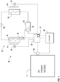
- a transport refrigeration system 20 includes a refrigeration unit 22.
- the refrigeration unit 22 functions, under the control of a controller 30, to establish and regulate a desired product storage temperature within a refrigerated cargo space wherein a perishable product is stored during transport and to maintain the product storage temperature within a specified temperature range.
- the refrigerated cargo space may be the cargo box of a trailer, a truck, a seaboard shipping container or an intermodal container wherein perishable cargo, such as, for example, produce, meat, poultry, fish, dairy products, cut flowers, pharmaceuticals, and other fresh or frozen perishable products, is stowed for transport.
- the refrigeration unit 22 includes a refrigerant compression device 32, a refrigerant heat rejection heat exchanger 34, an expansion device 36, and a refrigerant heat absorption heat exchanger 38 connected in refrigerant flow communication in a closed loop refrigerant circuit and arranged in a conventional refrigeration cycle.
- the refrigeration unit 22 also includes one or more fans 40 associated with the refrigerant heat rejection heat exchanger 34 and driven by fan motor(s) 42 and one or more fans 44 associated with the refrigerant heat absorption heat exchanger 38 and driven by fan motor(s) 46.
- the refrigeration unit 22 may also include an electric resistance heater 48 associated with the refrigerant heat absorption heat exchanger 38.
- the electric resistance heater 48 may be used, for example, for defrost or temperature control. It is to be understood that other components (not shown) may be incorporated into the refrigerant circuit as desired, including for example, but not limited to, a suction modulation valve, a receiver, a filter/dryer, an economizer circuit.
- the refrigerant heat rejection heat exchanger 34 may, for example, comprise one or more refrigerant conveying coiled tubes or one or more tube banks formed of a plurality of refrigerant conveying tubes extending between respective inlet and outlet manifolds.
- the fan(s) 40 are operative to pass air, typically ambient air, across the tubes of the refrigerant heat rejection heat exchanger 34 to cool refrigerant vapor passing through the tubes.
- the refrigerant heat rejection heat exchanger 34 may operate either as a refrigerant condenser, such as if the refrigeration unit 22 is operating in a subcritical refrigerant cycle or as a refrigerant gas cooler, such as if the refrigeration unit 22 is operating in a transcritical cycle.
- the refrigerant heat absorption heat exchanger 38 may, for example, also comprise one or more refrigerant conveying coiled tubes or one or more tube banks formed of a plurality of refrigerant conveying tubes extending between respective inlet and outlet manifolds.
- the fan(s) 44 are operative to pass air drawn from the temperature controlled cargo box across the tubes of the refrigerant heat absorption heat exchanger 38 to heat and evaporate refrigerant liquid passing through the tubes and cool the air.
- the air cooled in traversing the refrigerant heat rejection heat exchanger 38 is supplied back to the temperature controlled cargo box.
- air when used herein with reference to the atmosphere within the cargo box includes mixtures of air with other gases, such as for example, but not limited to, nitrogen or carbon dioxide, sometimes introduced into a refrigerated cargo box for transport of perishable produce.
- the refrigerant compression device 32 may comprise a single-stage or multiple-stage compressor such as, for example, a reciprocating compressor or a scroll compressor.
- the compression device 32 has a compression mechanism (not shown) driven by an electric motor 50.
- the motor 50 may be disposed internally within the compressor with a drive shaft interconnected with a shaft of the compression mechanism, all sealed within a common housing of the compression device 32.
- the refrigeration system 20 also includes a controller 30 configured for controlling operation of the refrigeration system 20 including, but not limited to, operation of various components of the refrigerant unit 22 to provide and maintain a desired thermal environment within the cargo box of the truck or trailer, that is within the temperature controlled space in which a perishable product is stowed.
- the controller 30 may be an electronic controller including a microprocessor and an associated memory.
- the controller 30 controls operation of various components of the refrigerant unit 22, such as the refrigerant compression device 32 and its associated drive motor 50, the fan motors 42, 46 and the electric resistance heater 48.
- the refrigeration unit 22 has a plurality of power demand loads, including, but not limited to, the compression device drive motor 50, the drive motor 42 for the fan 40 associated with the refrigerant heat rejection heat exchanger 34, and the drive motor 46 for the fan 44 associated with the refrigerant heat absorption heat exchanger 38.
- the electric resistance heater 48 also constitutes a power demand load.
- the electric resistance heater may be selectively operated by the controller 30 whenever a control temperature within the temperature controlled cargo box drops below a preset lower temperature limit, which may occur in a cold ambient environment. In such an event the controller 30 would activate the electric resistance heater 48 to heat air circulated over the electric resistance heater by the fan(s) 44 associated with the refrigerant heat absorption heat exchanger 38.
- the compression device 32 and its associated drive motor 50, the fan motors 42, 46 and the electric resistance heater 48 represent loads of the transport refrigeration unit 22.
- One or more of the loads is powered by AC power generated by an inverter assembly 52.
- the inverter assembly 52 includes a plurality of inverters that convert DC power from a DC power source 17 into AC power to power one or more loads of the transport refrigeration unit 22.
- the DC power source 17 may be a battery or may be an AC-DC converter that converts an AC input (e.g., from grid power and/or a generator) to DC power.
- One or more sensors 37 are installed at the inverter assembly 52 to monitor a load on the one or more operating inverters in the inverter assembly 52.
- the sensor(s) 37 may monitor load on an inverter by measuring electrical parameters (e.g., current, voltage, power) and/or physical parameters (e.g., temperature).
- FIG. 2 depicts the inverter assembly 52 in further detail in an example embodiment.
- the inverter assembly 52 includes at least two inverters 60 1 - 60 N having an input connected to the DC power source 17 and an output connected to at least one load of the refrigeration unit 22.
- Example loads shown in FIG. 2 include the compression device 32, fan motors 42 and 46 and heater 48.
- the outputs of the inverters 60 1 - 60 N are connected in electrical parallel to a common AC output 62.
- a sensor 37 is shown associated with inverter N, but it should be understood that a sensor 37 may be associated with each individual inverter 60.
- the sensor(s) 37 may monitor load on an inverter 60 by measuring electrical parameters (e.g., current, voltage, power) and/or physical parameters (e.g., temperature).
- the inverters 60 1 - 60 N may all have a similar power rating and may be identical devices in an example embodiment.
- the controller 30 is in communication with the inverters 60 1 - 60 N and the sensor(s) 37.
- the controller 30 sends commands to each of the inverters 60 1 - 60 N to enter an active state (i.e., produce AC power) or an inactive state (i.e., do not produce AC power).
- the controller 30 determines how many inverters 60 1 - 60 N should be in an active state in response to parameters measured by one or more sensors 37.
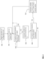
- FIG. 3 is a flowchart of a process for controlling the inverters 60 1 - 60 N in an example embodiment.
- the process begins at 500 where the refrigeration unit 22 begins operation and a single inverter 60 1 is set to the active state to produce AC power at 502.
- the controller 30 determines if the load on each inverter in the active state is greater than an upper threshold. At this point, only one inverter 60 1 is in the active state.
- the load on each inverter in the active state may be determined based on sensors 37 associated with the inverters 60 1 - 60 N .
- the sensor(s) 37 may monitor load on an inverter 60 by measuring electrical parameters (e.g., current, voltage, power) and/or physical parameters (e.g., temperature).
- the upper threshold may be represented as a percentage (e.g., 90% electrical limit or 90% of temperature limit) or as a numerical value (e.g., current greater than 8 Amps or temperature greater than 120 degrees Fahrenheit (49°C)).
- the controller 30 determines that the load on each inverter in the active state is less than the upper threshold, the refrigeration unit 22 continues to operate with the current number of inverters 60 in an active state. If at 504, the controller 30 determines that the load on each inverter in the active state is greater than the upper threshold, flow proceeds to 506 where the number of active inverters 60 is increased by 1, until all the inverters are in use. The controller 30 sends a command to another inverter 60 2 to enter an active state. At this stage, the two inverters 60 1 and 60 2 provide AC power to supply the loads of the refrigeration unit 22.
- the controller 30 determines if the load on each inverter 60 in the active state is less than a lower threshold.
- the lower threshold may be represented as a percentage (e.g., 25% electrical limit or 30% of temperature limit) or as a numerical value (e.g., current less than 1 Amp or temperature less than 40 degrees Fahrenheit (4°C)).
- the controller 30 determines that the load on each inverter 60 in the active state is not less than the lower threshold, flow proceeds to 504 and the number of inverters 60 in the active state remains the same. If at 508, the controller 30 determines that the load on each inverter 60 in the active state is less than the lower threshold, flow proceeds to 510. At 510, the controller 30 sends a command to decrease the number of inverters 60 in the active state, unless there is only one inverter in the active state. For example, if two inverters 60 1 and 60 2 are operating at a load less than the lower threshold (e.g., each producing less than 1 Amp), there is no need to have both inverters 60 1 and 60 2 in the active state. At 510, one of inverters 60 1 and 60 2 would be changed to the inactive state.
- the lower threshold e.g., each producing less than 1 Amp
- a number of techniques may be used to control the AC output of each inverter 60 1 - 60 N so that the AC outputs can be effectively paralleled at common AC output 62.
- the controller 30 and/or the inverters 60 1 - 60 N communicate to synchronize the AC outputs of each inverter 60 1 - 60 N in frequency and phase so the AC outputs can be effectively paralleled at common AC output 62.
- Each inverter 60 1 - 60 N may include a local controller to enable communications between inverters 60 1 - 60 N .
- a first inverter 60 1 communicates to the second inverter 60 2 when a reference point has occurred in a pulse width modulation (PWM) signal from controller 30.
- PWM pulse width modulation
- the second inverter 60 2 determines when the reference point occurs in its PWM signal from controller 30. If there is a difference between when the reference point occurs in the first PWM signal at the first inverter 60 1 and when the reference point occurs in the second PWM signal at the second inverter 60 2 , then one or both of the first inverter 60 1 and the second inverter 60 2 may adjust the period of the PWM signals such that the reference points occur at the same time.
- the first inverter 60 1 and the second inverter 60 2 may use known techniques to adjust the period of the PWM signals, such as a phase locked loop technique to reduce error between when the reference points occurs in control signal and when the reference point occurs in control signal. This improves synchronization of the control signals between first inverter 60 1 and the second inverter 60 2 .
- the control signal synchronization as described may be used with any number of inverters 60.
- the inverters 60 1 - 60 N may be multiphase inverters, producing multiphase AC outputs. In this configuration, each individual phase from each inverter 60 1 - 60 N would be paralleled at the common AC output 62.
- Embodiments of the invention allow the use of multiple inverters 60 1 - 60 N , connected in electrical parallel. This allows a single inverter design to be used, which reduces complexity in using a single inverter customized for a specific refrigeration unit loads. For high power loads, embodiments can simply use additional inverters arranged in parallel, rather than a customized high power inverter.
- embodiments can be in the form of processor-implemented processes and devices for practicing those processes, such as a processor in controller 30.
- Embodiments can also be in the form of computer program code containing instructions embodied in tangible media, such as network cloud storage, SD cards, flash drives, diskettes, CD ROMs, hard drives, or any other computer-readable storage medium, wherein, when the computer program code is loaded into and executed by a computer, the computer becomes a device for practicing the embodiments.
- Embodiments can also be in the form of computer program code, for example, whether stored in a storage medium, loaded into and/or executed by a computer, or transmitted over some transmission medium, loaded into and/or executed by a computer, or transmitted over some transmission medium, such as over electrical wiring or cabling, through fiber optics, or via electromagnetic radiation, wherein, when the computer program code is loaded into an executed by a computer, the computer becomes an device for practicing the embodiments.
- the computer program code segments configure the microprocessor to create specific logic circuits.
Landscapes
- Engineering & Computer Science (AREA)
- Physics & Mathematics (AREA)
- Mechanical Engineering (AREA)
- Thermal Sciences (AREA)
- Power Engineering (AREA)
- General Engineering & Computer Science (AREA)
- Devices That Are Associated With Refrigeration Equipment (AREA)
- Control Of Multiple Motors (AREA)
- Inverter Devices (AREA)
Applications Claiming Priority (1)
| Application Number | Priority Date | Filing Date | Title |
|---|---|---|---|
| US17/503,624 US12244245B2 (en) | 2021-10-18 | 2021-10-18 | Transport refrigeration system with paralleled inverters |
Publications (2)
| Publication Number | Publication Date |
|---|---|
| EP4166874A2 true EP4166874A2 (fr) | 2023-04-19 |
| EP4166874A3 EP4166874A3 (fr) | 2023-04-26 |
Family
ID=83898463
Family Applications (1)
| Application Number | Title | Priority Date | Filing Date |
|---|---|---|---|
| EP22201914.3A Pending EP4166874A3 (fr) | 2021-10-18 | 2022-10-17 | Système de réfrigération de transport avec onduleurs parallèles |
Country Status (3)
| Country | Link |
|---|---|
| US (1) | US12244245B2 (fr) |
| EP (1) | EP4166874A3 (fr) |
| CN (1) | CN115991079A (fr) |
Family Cites Families (25)
| Publication number | Priority date | Publication date | Assignee | Title |
|---|---|---|---|---|
| US6622505B2 (en) | 2001-06-08 | 2003-09-23 | Thermo King Corporation | Alternator/invertor refrigeration unit |
| JP4029935B2 (ja) | 2003-12-02 | 2008-01-09 | 株式会社日立製作所 | 冷凍装置及びインバータ装置 |
| US20050151019A1 (en) * | 2003-12-18 | 2005-07-14 | Curtis Edgar Stevens | Electrically pressurized on-board inert gas generation system |
| US7164242B2 (en) | 2004-02-27 | 2007-01-16 | York International Corp. | Variable speed drive for multiple loads |
| US7193826B2 (en) | 2004-02-27 | 2007-03-20 | York International Corporation | Motor disconnect arrangement for a variable speed drive |
| EP1796255B1 (fr) | 2004-06-21 | 2016-02-17 | Toshiba Carrier Corporation | Climatisation |
| JP2007113874A (ja) | 2005-10-21 | 2007-05-10 | Daikin Ind Ltd | トレーラー用冷凍装置 |
| NL1030481C2 (nl) | 2005-11-22 | 2007-05-23 | Atlas Copco Airpower Nv | Inrichting voor aansluiting op een impedantie met een voornamelijk inductief karakter. |
| US8014110B2 (en) | 2007-01-22 | 2011-09-06 | Johnson Controls Technology Company | Variable speed drive with integral bypass contactor |
| KR20100003580A (ko) | 2008-07-01 | 2010-01-11 | 엘지전자 주식회사 | 공기조화기의 전동기 제어장치 |
| US8098505B1 (en) * | 2009-07-20 | 2012-01-17 | Fairchild Semiconductor Corporation | Phase management for interleaved power factor correction |
| JP5929127B2 (ja) | 2011-11-29 | 2016-06-01 | 富士電機株式会社 | 並列インバータ装置の誤配線検出装置 |
| US20140180953A1 (en) | 2012-12-20 | 2014-06-26 | Purfresh, Inc. | Methods and systems for controlled distribution of perishable goods |
| US9927165B2 (en) | 2014-02-06 | 2018-03-27 | Electronic Power Design, Inc. | Hybrid cooling system |
| US10495340B2 (en) | 2014-09-05 | 2019-12-03 | Samsung Electronics Co., Ltd. | Inverter circuit, and air conditioner and refrigerator using the same |
| WO2016035216A1 (fr) | 2014-09-05 | 2016-03-10 | 三菱電機株式会社 | Dispositif de conversion de puissance et dispositif d'entraînement de moteur, ventilateur et compresseur chacun pourvu de celui-ci, et machine de climatisation, réfrigérateur et machine de congélation pourvus chacun d'un ventilateur et/ou d'un compresseur |
| US10128775B2 (en) | 2014-11-04 | 2018-11-13 | Mitsubishi Electric Corporation | Motor drive apparatus and air conditioner |
| WO2016071965A1 (fr) | 2014-11-04 | 2016-05-12 | 三菱電機株式会社 | Appareil pompe à chaleur ainsi que climatiseur, chauffe-eau à pompe à chaleur et réfrigérateur pourvus de celui-ci |
| JP6440849B2 (ja) | 2015-08-28 | 2018-12-19 | 三菱電機株式会社 | モータ駆動装置並びにモータ駆動装置を用いたヒートポンプ装置及び冷凍空調装置 |
| KR20180079821A (ko) | 2017-01-02 | 2018-07-11 | 엘지전자 주식회사 | 칠러 |
| RU196661U1 (ru) | 2018-11-30 | 2020-03-11 | Общество с ограниченной ответственностью "Ликинский автобусный завод" (ООО "ЛиАЗ") | Устройство охлаждения тягового электрооборудования электрического транспортного средства |
| US11376922B2 (en) | 2019-09-09 | 2022-07-05 | Thermo King Corporation | Transport climate control system with a self-configuring matrix power converter |
| US11135894B2 (en) | 2019-09-09 | 2021-10-05 | Thermo King Corporation | System and method for managing power and efficiently sourcing a variable voltage for a transport climate control system |
| EP3820041A1 (fr) | 2019-11-05 | 2021-05-12 | Carrier Corporation | Entraînement doté de modules d'onduleur à niveaux multiples |
| MX2022012114A (es) | 2020-03-31 | 2022-10-18 | Goodman Global Group Inc | Sistema inversor para un sistema de calefaccion, ventilacion y aire acondicionado. |
-
2021
- 2021-10-18 US US17/503,624 patent/US12244245B2/en active Active
-
2022
- 2022-10-17 CN CN202211265406.3A patent/CN115991079A/zh active Pending
- 2022-10-17 EP EP22201914.3A patent/EP4166874A3/fr active Pending
Also Published As
| Publication number | Publication date |
|---|---|
| US20230119462A1 (en) | 2023-04-20 |
| EP4166874A3 (fr) | 2023-04-26 |
| CN115991079A (zh) | 2023-04-21 |
| US12244245B2 (en) | 2025-03-04 |
Similar Documents
| Publication | Publication Date | Title |
|---|---|---|
| US11118833B2 (en) | Battery system for refrigerated transport container | |
| US9297578B2 (en) | Current limit control on a transport refrigeration system | |
| US11548353B2 (en) | Battery powered transportation refrigeration unit with variable inverter | |
| US20150000636A1 (en) | Method And System For Adjusting Engine Speed In A Transport Refrigeration System | |
| US12391097B2 (en) | Transport refrigeration system and method of operating | |
| US10144291B2 (en) | Continuous voltage control of a transport refrigeration system | |
| US10823484B2 (en) | Intelligent voltage control for electric heat and defrost in transport refrigeration system | |
| EP4080708A1 (fr) | Bloc-batterie ca doté d'électronique et de refroidissement intégrés | |
| EP4063151B1 (fr) | Architecture électrique d'alimentation de multiples unités de réfrigération de transport | |
| CN114643924B (zh) | 运输制冷系统 | |
| EP4166874A2 (fr) | Système de réfrigération de transport avec onduleurs parallèles | |
| US11667229B2 (en) | Natural gas tank pressure control for transport refrigeration unit | |
| US10759326B2 (en) | Method for determining reduced airflow in transport refrigeration system | |
| EP3426512B1 (fr) | Procédé de dégivrage de grille d'admission d'air de retour |
Legal Events
| Date | Code | Title | Description |
|---|---|---|---|
| PUAI | Public reference made under article 153(3) epc to a published international application that has entered the european phase |
Free format text: ORIGINAL CODE: 0009012 |
|
| STAA | Information on the status of an ep patent application or granted ep patent |
Free format text: STATUS: THE APPLICATION HAS BEEN PUBLISHED |
|
| PUAL | Search report despatched |
Free format text: ORIGINAL CODE: 0009013 |
|
| AK | Designated contracting states |
Kind code of ref document: A2 Designated state(s): AL AT BE BG CH CY CZ DE DK EE ES FI FR GB GR HR HU IE IS IT LI LT LU LV MC ME MK MT NL NO PL PT RO RS SE SI SK SM TR |
|
| AK | Designated contracting states |
Kind code of ref document: A3 Designated state(s): AL AT BE BG CH CY CZ DE DK EE ES FI FR GB GR HR HU IE IS IT LI LT LU LV MC ME MK MT NL NO PL PT RO RS SE SI SK SM TR |
|
| RIC1 | Information provided on ipc code assigned before grant |
Ipc: B60P 3/20 20060101ALI20230321BHEP Ipc: F25B 49/02 20060101AFI20230321BHEP |
|
| P01 | Opt-out of the competence of the unified patent court (upc) registered |
Effective date: 20230527 |
|
| STAA | Information on the status of an ep patent application or granted ep patent |
Free format text: STATUS: REQUEST FOR EXAMINATION WAS MADE |
|
| RBV | Designated contracting states (corrected) |
Designated state(s): AL AT BE BG CH CY CZ DE DK EE ES FI FR GB GR HR HU IE IS IT LI LT LU LV MC ME MK MT NL NO PL PT RO RS SE SI SK SM TR |
|
| 17P | Request for examination filed |
Effective date: 20231026 |
|
| STAA | Information on the status of an ep patent application or granted ep patent |
Free format text: STATUS: EXAMINATION IS IN PROGRESS |
|
| 17Q | First examination report despatched |
Effective date: 20260209 |