EP4167008A2 - Optische linsenanordnung und kopfmontierte vorrichtung - Google Patents
Optische linsenanordnung und kopfmontierte vorrichtung Download PDFInfo
- Publication number
- EP4167008A2 EP4167008A2 EP22183616.6A EP22183616A EP4167008A2 EP 4167008 A2 EP4167008 A2 EP 4167008A2 EP 22183616 A EP22183616 A EP 22183616A EP 4167008 A2 EP4167008 A2 EP 4167008A2
- Authority
- EP
- European Patent Office
- Prior art keywords
- lens element
- lens
- optical
- lens assembly
- assembly
- Prior art date
- Legal status (The legal status is an assumption and is not a legal conclusion. Google has not performed a legal analysis and makes no representation as to the accuracy of the status listed.)
- Granted
Links
Images










Classifications
-
- G—PHYSICS
- G02—OPTICS
- G02B—OPTICAL ELEMENTS, SYSTEMS OR APPARATUS
- G02B9/00—Optical objectives characterised both by the number of the components and their arrangements according to their sign, i.e. + or -
- G02B9/60—Optical objectives characterised both by the number of the components and their arrangements according to their sign, i.e. + or - having five components only
-
- G—PHYSICS
- G02—OPTICS
- G02B—OPTICAL ELEMENTS, SYSTEMS OR APPARATUS
- G02B1/00—Optical elements characterised by the material of which they are made; Optical coatings for optical elements
- G02B1/002—Optical elements characterised by the material of which they are made; Optical coatings for optical elements made of materials engineered to provide properties not available in nature, e.g. metamaterials
-
- G—PHYSICS
- G02—OPTICS
- G02B—OPTICAL ELEMENTS, SYSTEMS OR APPARATUS
- G02B13/00—Optical objectives specially designed for the purposes specified below
- G02B13/001—Miniaturised objectives for electronic devices, e.g. portable telephones, webcams, PDAs, small digital cameras
- G02B13/0015—Miniaturised objectives for electronic devices, e.g. portable telephones, webcams, PDAs, small digital cameras characterised by the lens design
- G02B13/002—Miniaturised objectives for electronic devices, e.g. portable telephones, webcams, PDAs, small digital cameras characterised by the lens design having at least one aspherical surface
- G02B13/0045—Miniaturised objectives for electronic devices, e.g. portable telephones, webcams, PDAs, small digital cameras characterised by the lens design having at least one aspherical surface having five or more lenses
-
- G—PHYSICS
- G02—OPTICS
- G02B—OPTICAL ELEMENTS, SYSTEMS OR APPARATUS
- G02B27/00—Optical systems or apparatus not provided for by any of the groups G02B1/00 - G02B26/00, G02B30/00
- G02B27/0025—Optical systems or apparatus not provided for by any of the groups G02B1/00 - G02B26/00, G02B30/00 for optical correction, e.g. distorsion, aberration
-
- G—PHYSICS
- G02—OPTICS
- G02B—OPTICAL ELEMENTS, SYSTEMS OR APPARATUS
- G02B27/00—Optical systems or apparatus not provided for by any of the groups G02B1/00 - G02B26/00, G02B30/00
- G02B27/01—Head-up displays
- G02B27/017—Head mounted
- G02B27/0172—Head mounted characterised by optical features
-
- G—PHYSICS
- G02—OPTICS
- G02B—OPTICAL ELEMENTS, SYSTEMS OR APPARATUS
- G02B3/00—Simple or compound lenses
- G02B3/02—Simple or compound lenses with non-spherical faces
- G02B3/04—Simple or compound lenses with non-spherical faces with continuous faces that are rotationally symmetrical but deviate from a true sphere, e.g. so called "aspheric" lenses
-
- G—PHYSICS
- G02—OPTICS
- G02B—OPTICAL ELEMENTS, SYSTEMS OR APPARATUS
- G02B27/00—Optical systems or apparatus not provided for by any of the groups G02B1/00 - G02B26/00, G02B30/00
- G02B27/01—Head-up displays
- G02B27/0101—Head-up displays characterised by optical features
- G02B2027/0132—Head-up displays characterised by optical features comprising binocular systems
- G02B2027/0134—Head-up displays characterised by optical features comprising binocular systems of stereoscopic type
Definitions
- the present disclosure relates to an optical lens assembly. More particularly, the present disclosure relates to a compact optical lens assembly applicable to head-mounted devices.
- an optical lens assembly includes five lens elements, the five lens elements being, in order from a magnification side to a reduction side, a first lens element, a second lens element, a third lens element, a fourth lens element and a fifth lens element.
- Each of the five lens elements has an m-side surface facing towards the magnification side and an r-side surface facing towards the reduction side.
- the m-side surface of the second lens element is concave in a paraxial region thereof.
- At least one surface of at least one of the five lens elements includes at least one inflection point.
- the optical lens assembly further includes an aperture stop.
- the fifth lens element has negative refractive power.
- the first lens element has positive refractive power; the second lens element has negative refractive power; the third lens element has positive refractive power.
- At least three lens elements of the optical lens assembly are made of plastic material; at least one lens element of the optical lens assembly is made of glass material.
- the axial distance between the first lens element and the second lens element is the maximum among each axial distance of adjacent lens elements of the optical lens assembly.
- a number of the projection lens assemblies of the projecting module of the light field display system is at least 5 and at most 15.
- the first lens element can have positive refractive power, so that it is favorable for moving the aperture stop towards the magnification side so as to receive more light for enhancing image illuminance.
- the m-side surface of the first lens element can be convex in a paraxial region thereof and the r-side surface of the first lens element can be convex in a paraxial region thereof. Therefore, it is favorable for preventing excessive curvature of a single surface by balancing refractive power on the surfaces of the lens element.
- the second lens element can have negative refractive power, so that it is favorable for receiving light from a large field of view and also optimizing the light of different wavelengths.
- the m-side surface of the second lens element can be concave in a paraxial region thereof, so that it is favorable for enlarging the field of view.
- the r-side surface of the second lens element can be convex in a paraxial region thereof, so that it is favorable for preventing total reflection by restricting the incident angle of light.
- the fifth lens element can have negative refractive power, so that it is favorable for balancing the field of view of the optical lens assembly to meet the practical specifications of the device.
- the r-side surface of the fifth lens element can be concave in a paraxial region thereof. Therefore, it is favorable for adjusting the back focal length of the optical lens assembly so as to avoid the overly large volume of the optical lens assembly.
- a central thickness of the second lens element is CT2
- a central thickness of the fourth lens element is CT4
- the following condition is satisfied: 0.40 ⁇ CT2/CT4 ⁇ 9.0. Therefore, it is favorable for balancing the central thicknesses of the second lens element and the fourth lens element so as to increase the yield rate. Further, the following condition can be satisfied: 0.65 ⁇ CT2/CT4 ⁇ 4.50. Moreover, the following condition can be satisfied: 0.85 ⁇ CT2/CT4 ⁇ 2.50.
- a central thickness of the third lens element is CT3, and a minimum central thickness of the five lens elements of the optical lens assembly is CTmin, the following condition is satisfied: 1.60 ⁇ CT3/CTmin ⁇ 10.0. Therefore, it is favorable for providing the main refractive power of the optical lens assembly by arranging the third lens element with sufficient thickness. Further, the following condition can be satisfied: 2.20 ⁇ CT3/CTmin ⁇ 7.0. Moreover, the following condition can be satisfied: 3.80 ⁇ CT3/CTmin ⁇ 7.0.
- an axial distance between the first lens element and the second lens element is T12
- an axial distance between the second lens element and the third lens element is T23
- an axial distance between the third lens element and the fourth lens element is T34
- an axial distance between the fourth lens element and the fifth lens element is T45
- the following condition is satisfied: 0.25 ⁇ T12/(T23+T34+T45) ⁇ 9.0. Therefore, it is favorable for reducing the angle between the chief ray and the r-side conjugate surface by providing sufficient adjusting space for the light path between the first lens element and the second lens element. Further, the following condition can be satisfied: 0.45 ⁇ T12/(T23+T34+T45) ⁇ 4.0.
- the central thickness of the third lens element is CT3, and a central thickness of the fifth lens element is CT5, the following condition is satisfied: 1.20 ⁇ CT3/CT5 ⁇ 9.0. Therefore, it is favorable for enhancing the controlling ability of the third lens element in the optical lens assembly and performing the fifth lens element as a lens element for correction so as to correct off-axis aberrations. Further, the following condition can be satisfied: 3.0 ⁇ CT3/CT5 ⁇ 7.0.
- the central thickness of the second lens element is CT2
- the axial distance between the first lens element and the second lens element is T12
- the following condition is satisfied: 0.90 ⁇ CT2/T12 ⁇ 5.0. Therefore, it is favorable for balancing the ratio between the second lens element and the occupied space of the second lens element, and also favorable for satisfying the manufacturability and the yield rate. Further, the following condition can be satisfied: 1.0 ⁇ CT2/T12 ⁇ 3.0.
- the following condition is satisfied: 10.0 ⁇ V5 ⁇ 50.0. Therefore, it is favorable for enhancing the controlling ability for the light path of the fifth lens element so as to balance aberrations of the optical lens assembly. Further, the following condition can be satisfied: 10.0 ⁇ V5 ⁇ 25.0. Moreover, the following condition can be satisfied: 10.0 ⁇ V5 ⁇ 20.0.
- the equation of the aspheric surface is the same as 1st embodiment. Further, the definition of the parameters of the following table is the same as 1st embodiment, and will not be defined again.
- the second lens element E2 with negative refractive power has an m-side surface being concave in a paraxial region thereof and an r-side surface being convex in a paraxial region thereof.
- the second lens element E2 is made of plastic material, and has the m-side surface and the r-side surface being both aspheric. Further, the m-side surface of the second lens element E2 includes an inflection point.
- Table 4A The detailed optical data of the 4th embodiment are shown in Table 4A and the aspheric surface data are shown in Table 4B below.
- the equation of the aspheric surface is the same as 1st embodiment. Further, the definition of the parameters of the following table is the same as 1st embodiment, and will not be defined again.
- the second lens element E2 with negative refractive power has an m-side surface being concave in a paraxial region thereof and an r-side surface being convex in a paraxial region thereof.
- the second lens element E2 is made of plastic material, and has the m-side surface and the r-side surface being both aspheric. Further, the m-side surface of the second lens element E2 includes an inflection point.
- the fourth lens element E4 with negative refractive power has an m-side surface being concave in a paraxial region thereof and an r-side surface being convex in a paraxial region thereof.
- the fourth lens element E4 is made of plastic material, and has the m-side surface and the r-side surface being both aspheric. Further, the m-side surface of the fourth lens element E4 includes an inflection point, and the r-side surface of the fourth lens element E4 includes an inflection point.
- the fifth lens element E5 with negative refractive power has an m-side surface being concave in a paraxial region thereof and an r-side surface being convex in a paraxial region thereof.
- the fifth lens element E5 is made of plastic material, and has the m-side surface and the r-side surface being both aspheric. Further, the m-side surface of the fifth lens element E5 includes an inflection point, and the r-side surface of the fifth lens element E5 includes an inflection point.
- the equation of the aspheric surface is the same as 1st embodiment. Further, the definition of the parameters of the following table is the same as 1st embodiment, and will not be defined again.
- a vertical distance between the inflection point closest to an optical axis on one of the m-side or r-side surfaces of the third lens element E3 and the optical axis is Yc3
- a vertical distance between the inflection point closest to the optical axis on one of the m-side or r-side surfaces of the fourth lens element E4 and the optical axis is Yc4
- a vertical distance between the inflection point closest to the optical axis on one of the m-side or r-side surfaces of the fifth lens element E5 and the optical axis is Yc5.
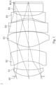
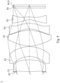
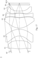
- Fig. 11 is a schematic view of an optical lens assembly 6 according to the 6th embodiment of the present disclosure.
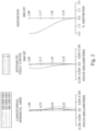
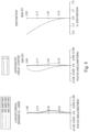
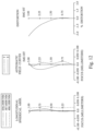
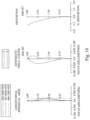
- Fig. 12 shows spherical aberration curves, astigmatic field curves and a distortion curve of the optical lens assembly 6 according to the 6th embodiment.
- the optical lens assembly 6 includes, in order from a magnification side to a reduction side, an aperture stop ST, a first lens element E1, a second lens element E2, a third lens element E3, a fourth lens element E4, a fifth lens element E5, a filter E6 and an r-side conjugate surface RCS.
- the optical lens assembly 6 includes five lens elements (E1, E2, E3, E4, E5) without additional one or more lens elements inserted between the first lens element E1 and the fifth lens element E5.
- the first lens element E1 with positive refractive power has an m-side surface being convex in a paraxial region thereof and an r-side surface being convex in a paraxial region thereof.
- the first lens element E1 is made of plastic material, and has the m-side surface and the r-side surface being both aspheric. Further, the m-side surface of the first lens element E1 includes an inflection point.
- the third lens element E3 with positive refractive power has an m-side surface being convex in a paraxial region thereof and an r-side surface being convex in a paraxial region thereof.
- the third lens element E3 is made of glass material, and has the m-side surface and the r-side surface being both aspheric. Further, the m-side surface of the third lens element E3 includes an inflection point.
- a vertical distance between the inflection point closest to an optical axis on one of the m-side or r-side surfaces of the third lens element E3 and the optical axis is Yc3
- a vertical distance between the inflection point closest to the optical axis on one of the m-side or r-side surfaces of the fourth lens element E4 and the optical axis is Yc4
- a vertical distance between the inflection point closest to the optical axis on one of the m-side or r-side surfaces of the fifth lens element E5 and the optical axis is Yc5.
- the second lens element E2 with negative refractive power has an m-side surface being concave in a paraxial region thereof and an r-side surface being concave in a paraxial region thereof.
- the second lens element E2 is made of plastic material, and has the m-side surface and the r-side surface being both aspheric. Further, the m-side surface of the second lens element E2 includes an inflection point, and the r-side surface of the second lens element E2 includes two inflection points.
- the third lens element E3 with positive refractive power has an m-side surface being convex in a paraxial region thereof and an r-side surface being convex in a paraxial region thereof.
- the third lens element E3 is made of plastic material, and has the m-side surface and the r-side surface being both aspheric. Further, the m-side surface of the third lens element E3 includes two inflection points, and the r-side surface of the third lens element E3 includes an inflection point.
- the fourth lens element E4 with positive refractive power has an m-side surface being convex in a paraxial region thereof and an r-side surface being convex in a paraxial region thereof.
- the fourth lens element E4 is made of plastic material, and has the m-side surface and the r-side surface being both aspheric. Further, the m-side surface of the fourth lens element E4 includes two inflection points, and the r-side surface of the fourth lens element E4 includes an inflection point.
- the fifth lens element E5 with negative refractive power has an m-side surface being concave in a paraxial region thereof and an r-side surface being concave in a paraxial region thereof.
- the fifth lens element E5 is made of plastic material, and has the m-side surface and the r-side surface being both aspheric. Further, the m-side surface of the fifth lens element E5 includes two inflection points, and the r-side surface of the fifth lens element E5 includes an inflection point.
- the equation of the aspheric surface is the same as 1st embodiment. Further, the definition of the parameters of the following table is the same as 1st embodiment, and will not be defined again.
- Table 7C these parameters can be calculated from Table 7A and Table 7B as the following values and satisfy the following conditions: Table 7C - 7th Embodiment f [mm] 6.26 T12/(T23+T34+T45) 1.11 Fno 1.29 TD/ ⁇ CT 1.19 HFOV [degrees] 26.4 (R3+R4)/(R3-R4) 0.08 Nmax 1.686 (
- a vertical distance between the inflection point closest to an optical axis on one of the m-side or r-side surfaces of the third lens element E3 and the optical axis is Yc3
- a vertical distance between the inflection point closest to the optical axis on one of the m-side or r-side surfaces of the fourth lens element E4 and the optical axis is Yc4
- a vertical distance between the inflection point closest to the optical axis on one of the m-side or r-side surfaces of the fifth lens element E5 and the optical axis is Yc5.
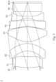
- Fig. 15 is a schematic view of an optical lens assembly 8 according to the 8th embodiment of the present disclosure.
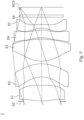
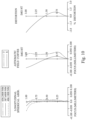
- Fig. 16 shows spherical aberration curves, astigmatic field curves and a distortion curve of the optical lens assembly 8 according to the 8th embodiment.
- the optical lens assembly 8 includes, in order from a magnification side to a reduction side, an aperture stop ST, a first lens element E1, a second lens element E2, a third lens element E3, a fourth lens element E4, a fifth lens element E5, a filter E6 and an r-side conjugate surface RCS.
- the optical lens assembly 8 includes five lens elements (E1, E2, E3, E4, E5) without additional one or more lens elements inserted between the first lens element E1 and the fifth lens element E5.
- the second lens element E2 with negative refractive power has an m-side surface being concave in a paraxial region thereof and an r-side surface being concave in a paraxial region thereof.
- the second lens element E2 is made of plastic material, and has the m-side surface and the r-side surface being both aspheric. Further, the r-side surface of the second lens element E2 includes an inflection point.
- the second lens element E2 with negative refractive power has an m-side surface being concave in a paraxial region thereof and an r-side surface being convex in a paraxial region thereof.
- the second lens element E2 is made of plastic material, and has the m-side surface and the r-side surface being both aspheric. Further, the m-side surface of the second lens element E2 includes an inflection point, and the r-side surface of the second lens element E2 includes an inflection point.
- Table 9A The detailed optical data of the 9th embodiment are shown in Table 9A and the aspheric surface data are shown in Table 9B below.
- the equation of the aspheric surface is the same as 1st embodiment. Further, the definition of the parameters of the following table is the same as 1st embodiment, and will not be defined again.
- Table 9C these parameters can be calculated from Table 9A and Table 9B as the following values and satisfy the following conditions: Table 9C - 9th Embodiment f [mm] 6.31 T12/(T23+T34+T45) 2.41 Fno 1.30 TD/ ⁇ CT 1.21 HFOV [degrees] 26.2 (R3+R4)/(R3-R4) -3.94 Nmax 1.705 (
- a vertical distance between the inflection point closest to an optical axis on one of the m-side or r-side surfaces of the third lens element E3 and the optical axis is Yc3
- a vertical distance between the inflection point closest to the optical axis on one of the m-side or r-side surfaces of the fourth lens element E4 and the optical axis is Yc4
- a vertical distance between the inflection point closest to the optical axis on one of the m-side or r-side surfaces of the fifth lens element E5 and the optical axis is Yc5.
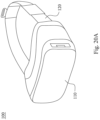
- Fig. 20A is a schematic view of a head-mounted device 100 according to the 10th embodiment of the present disclosure.
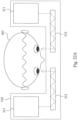
- Fig. 20B is a system schematic view of the head-mounted device 100 of Fig. 20A .
- the head-mounted device 100 includes a display system 110, and can include a positioning strap 120, which is for positioning the display system 110 in front of the eyes of a user 101 so as to provide a 3D image for the user 101.
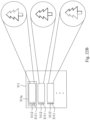
- each projecting module 311 includes at least three projection lens assemblies 311a, and each projection lens assembly 311a includes an optical lens assembly 3111 and an image source 3112. Further, a number of the projection lens assemblies 311a of the projecting module 311 of the light field display system 310 is at least 5 and at most 15. Therefore, it is favorable for providing a better image display.
- Each optical lens assembly 3111 can include at least three lens elements, one of the lens elements of the optical lens assembly 3111 can be made of plastic material and has a surface being aspheric.
- the optical lens assemblies 3111 can be any optical lens assembly in the aforementioned 1st to 9th embodiments, and the image sources 3112 can be DLP or LCD, but the present disclosure is not limited thereto.
Landscapes
- Physics & Mathematics (AREA)
- General Physics & Mathematics (AREA)
- Optics & Photonics (AREA)
- Lenses (AREA)
- Optical Head (AREA)
- Laser Beam Processing (AREA)
Priority Applications (1)
| Application Number | Priority Date | Filing Date | Title |
|---|---|---|---|
| EP25215688.0A EP4679163A3 (de) | 2021-08-25 | 2022-07-07 | Kopfmontierte vorrichtung |
Applications Claiming Priority (1)
| Application Number | Priority Date | Filing Date | Title |
|---|---|---|---|
| TW110131549A TWI811774B (zh) | 2021-08-25 | 2021-08-25 | 光學透鏡組及頭戴裝置 |
Related Child Applications (2)
| Application Number | Title | Priority Date | Filing Date |
|---|---|---|---|
| EP25215688.0A Division EP4679163A3 (de) | 2021-08-25 | 2022-07-07 | Kopfmontierte vorrichtung |
| EP25215688.0A Division-Into EP4679163A3 (de) | 2021-08-25 | 2022-07-07 | Kopfmontierte vorrichtung |
Publications (3)
| Publication Number | Publication Date |
|---|---|
| EP4167008A2 true EP4167008A2 (de) | 2023-04-19 |
| EP4167008A3 EP4167008A3 (de) | 2023-06-28 |
| EP4167008B1 EP4167008B1 (de) | 2026-03-04 |
Family
ID=82403512
Family Applications (2)
| Application Number | Title | Priority Date | Filing Date |
|---|---|---|---|
| EP25215688.0A Pending EP4679163A3 (de) | 2021-08-25 | 2022-07-07 | Kopfmontierte vorrichtung |
| EP22183616.6A Active EP4167008B1 (de) | 2021-08-25 | 2022-07-07 | Optische linsenanordnung und kopfmontierte vorrichtung |
Family Applications Before (1)
| Application Number | Title | Priority Date | Filing Date |
|---|---|---|---|
| EP25215688.0A Pending EP4679163A3 (de) | 2021-08-25 | 2022-07-07 | Kopfmontierte vorrichtung |
Country Status (4)
| Country | Link |
|---|---|
| US (1) | US12306465B2 (de) |
| EP (2) | EP4679163A3 (de) |
| CN (1) | CN115728908A (de) |
| TW (1) | TWI811774B (de) |
Families Citing this family (4)
| Publication number | Priority date | Publication date | Assignee | Title |
|---|---|---|---|---|
| TWI796921B (zh) * | 2022-01-03 | 2023-03-21 | 大立光電股份有限公司 | 光機引擎及投影裝置 |
| CN116859610B (zh) * | 2023-08-04 | 2025-11-04 | 浙江舜宇光学有限公司 | 虚拟现实设备 |
| CN119148340A (zh) * | 2024-11-01 | 2024-12-17 | 业成科技(成都)有限公司 | 镜头总成 |
| CN119355933B (zh) * | 2024-12-30 | 2025-05-13 | 江西联昊光电有限公司 | 光学镜头及近眼显示设备 |
Family Cites Families (45)
| Publication number | Priority date | Publication date | Assignee | Title |
|---|---|---|---|---|
| JPS5522762B2 (de) * | 1974-02-08 | 1980-06-19 | ||
| JPH07104180A (ja) | 1993-10-04 | 1995-04-21 | Ohara Inc | 広角レンズ |
| JP5095662B2 (ja) | 2009-03-31 | 2012-12-12 | カンタツ株式会社 | 固体撮像素子用撮像レンズ |
| CN201508432U (zh) | 2009-04-07 | 2010-06-16 | 富士能株式会社 | 摄像透镜及摄像装置 |
| TWI421557B (zh) * | 2009-07-14 | 2014-01-01 | 大立光電股份有限公司 | 攝像透鏡系統 |
| KR101709641B1 (ko) | 2009-12-21 | 2017-02-23 | 엘지이노텍 주식회사 | 촬상 렌즈 |
| JP5851157B2 (ja) * | 2011-08-25 | 2016-02-03 | リコー光学株式会社 | 接眼レンズ系および画像観察装置 |
| TWI439753B (zh) | 2012-03-03 | 2014-06-01 | Largan Precision Co Ltd | 攝像光學鏡片系統 |
| TWI461778B (zh) * | 2012-04-19 | 2014-11-21 | Largan Precision Co Ltd | 光學成像系統組 |
| WO2013175783A1 (ja) | 2012-05-23 | 2013-11-28 | 富士フイルム株式会社 | 撮像レンズおよび撮像レンズを備えた撮像装置 |
| TWI439754B (zh) | 2012-10-09 | 2014-06-01 | Largan Precision Co Ltd | 結像系統鏡頭組 |
| TWI468724B (zh) | 2012-12-25 | 2015-01-11 | Largan Precision Co Ltd | 影像擷取光學鏡片組 |
| TWI507726B (zh) | 2013-02-04 | 2015-11-11 | Largan Precision Co Ltd | 移動對焦光學鏡頭組 |
| CN103293644B (zh) * | 2013-02-06 | 2015-11-25 | 玉晶光电(厦门)有限公司 | 可携式电子装置与其光学成像镜头 |
| CN103412394B (zh) | 2013-03-19 | 2017-05-10 | 玉晶光电(厦门)有限公司 | 可携式电子装置与其光学成像镜头 |
| TWI457593B (zh) * | 2013-08-19 | 2014-10-21 | Largan Precision Co Ltd | 拾像系統鏡片組及取像裝置 |
| CN104914558B (zh) | 2014-03-14 | 2017-09-01 | 光燿科技股份有限公司 | 成像镜头组 |
| TWI493221B (zh) | 2014-03-14 | 2015-07-21 | Glory Science Co Ltd | 成像鏡頭組 |
| TWI541540B (zh) | 2014-04-03 | 2016-07-11 | 大立光電股份有限公司 | 攝影光學鏡組、取像裝置及可攜裝置 |
| TWI518360B (zh) | 2014-08-26 | 2016-01-21 | 大立光電股份有限公司 | 取像光學透鏡組、取像裝置以及電子裝置 |
| US10761313B2 (en) | 2014-08-29 | 2020-09-01 | Canon Kabushiki Kaisha | Eyepiece lens, observation apparatus, and imaging apparatus including the same |
| WO2016110883A1 (ja) | 2015-01-09 | 2016-07-14 | 株式会社ニコン | 撮像レンズおよび撮像装置 |
| TWI584017B (zh) | 2015-02-03 | 2017-05-21 | 先進光電科技股份有限公司 | 光學成像系統(四) |
| TWI591397B (zh) | 2015-02-03 | 2017-07-11 | 先進光電科技股份有限公司 | 光學成像系統(三) |
| TWI572893B (zh) | 2015-03-03 | 2017-03-01 | 先進光電科技股份有限公司 | 光學成像系統(二) |
| TWI579584B (zh) | 2015-03-03 | 2017-04-21 | 先進光電科技股份有限公司 | 光學成像系統(一) |
| US20200371323A1 (en) | 2015-10-20 | 2020-11-26 | DynaOptics Ldt | Camera and Lens Systems Using Off-Axis Free Form Elements and Methods Therefor |
| CN106707497B (zh) | 2015-11-13 | 2019-07-23 | 深圳纳德光学有限公司 | 大视场角高像质的目镜光学系统及头戴显示装置 |
| CN107024766B (zh) | 2016-02-02 | 2019-05-10 | 深圳纳德光学有限公司 | 大视场角高像质的目镜光学系统及头戴显示装置 |
| CN107390347B (zh) | 2016-05-16 | 2019-12-27 | 信泰光学(深圳)有限公司 | 成像镜头 |
| TWI663419B (zh) | 2016-05-16 | 2019-06-21 | 大陸商信泰光學(深圳)有限公司 | 成像鏡頭(十三) |
| US10802251B2 (en) | 2016-08-23 | 2020-10-13 | Largan Precision Co., Ltd. | Photographing optical lens assembly, image capturing apparatus and electronic device |
| CN106680974B (zh) * | 2017-02-17 | 2022-06-10 | 浙江舜宇光学有限公司 | 摄像镜头 |
| CN109932820A (zh) * | 2017-12-18 | 2019-06-25 | 中强光电股份有限公司 | 显示器 |
| US11698516B2 (en) | 2018-11-27 | 2023-07-11 | National Taiwan University | Head mounted display device and near-eye light field display device thereof |
| CN112147782B (zh) | 2019-06-26 | 2022-09-30 | 中强光电股份有限公司 | 光学镜头及头戴式显示设备 |
| CN210720853U (zh) | 2019-10-18 | 2020-06-09 | 南昌欧菲精密光学制品有限公司 | 光学成像系统、取像装置及电子装置 |
| WO2021102749A1 (zh) | 2019-11-27 | 2021-06-03 | 天津欧菲光电有限公司 | 光学成像系统、取像装置及电子设备 |
| CN112859288B (zh) | 2019-11-27 | 2024-06-18 | 江西欧菲光学有限公司 | 光学成像系统、取像装置及电子设备 |
| TWI710816B (zh) | 2020-04-01 | 2020-11-21 | 新鉅科技股份有限公司 | 五片式紅外線單焦點鏡片組 |
| CN211826694U (zh) | 2020-04-23 | 2020-10-30 | 南昌欧菲精密光学制品有限公司 | 光学镜头、取像模组及电子装置 |
| CN111624740B (zh) | 2020-07-03 | 2025-03-04 | 浙江舜宇光学有限公司 | 成像镜头 |
| WO2022044675A1 (ja) | 2020-08-27 | 2022-03-03 | 富士フイルム株式会社 | 観察光学系および光学装置 |
| CN112965204B (zh) | 2021-02-20 | 2022-06-10 | 天津欧菲光电有限公司 | 光学成像系统、取像模组、电子设备和汽车 |
| CN115248497B (zh) | 2021-04-28 | 2024-10-22 | 华为技术有限公司 | 光学镜头、摄像头模组和电子设备 |
-
2021
- 2021-08-25 TW TW110131549A patent/TWI811774B/zh active
- 2021-12-23 CN CN202111589130.XA patent/CN115728908A/zh active Pending
-
2022
- 2022-05-03 US US17/735,199 patent/US12306465B2/en active Active
- 2022-07-07 EP EP25215688.0A patent/EP4679163A3/de active Pending
- 2022-07-07 EP EP22183616.6A patent/EP4167008B1/de active Active
Also Published As
| Publication number | Publication date |
|---|---|
| TWI811774B (zh) | 2023-08-11 |
| EP4679163A3 (de) | 2026-03-18 |
| TW202309591A (zh) | 2023-03-01 |
| EP4679163A2 (de) | 2026-01-14 |
| US20230080616A1 (en) | 2023-03-16 |
| EP4167008A3 (de) | 2023-06-28 |
| CN115728908A (zh) | 2023-03-03 |
| US12306465B2 (en) | 2025-05-20 |
| EP4167008B1 (de) | 2026-03-04 |
Similar Documents
| Publication | Publication Date | Title |
|---|---|---|
| US12352932B2 (en) | Optical image capturing system, image capturing device and electronic device | |
| US12510737B2 (en) | Optical lens assembly, image capturing apparatus and electronic device | |
| US11982794B2 (en) | Optical photographing system, image capturing apparatus and electronic device | |
| US20250298222A1 (en) | Photographing optical lens assembly, image capturing device and electronic device | |
| US20230418030A1 (en) | Optical image capturing system | |
| US10649183B2 (en) | Image lens assembly and image capturing device | |
| US11480757B2 (en) | Imaging optical system, imaging apparatus and electronic device | |
| US10247924B2 (en) | Imaging optical lens system, image capturing apparatus and electronic device | |
| US20210231924A1 (en) | Image lens assembly system | |
| EP4167008A2 (de) | Optische linsenanordnung und kopfmontierte vorrichtung | |
| US9606328B2 (en) | Photographing optical lens assembly, image capturing unit and electronic device | |
| US9104014B2 (en) | Imaging lens system and image capturing device | |
| US11442256B2 (en) | Imaging optical lens assembly, imaging apparatus and electronic device | |
| US7692877B2 (en) | Optical lens system for taking image | |
| US20160327772A1 (en) | Optical image lens system | |
| CN114355579B (zh) | 光学镜头、摄像模组及电子设备 | |
| US10788648B2 (en) | Optical imaging lens, imaging device, and electronic device having the same | |
| US20130250442A1 (en) | Optical lens assembly | |
| US11487089B2 (en) | Image capturing optical lens assembly including five lenses of +−++− or +−−+− refractive powers, imaging apparatus and electronic device | |
| US20230052783A1 (en) | Infrared projection lens assembly and infrared projection module | |
| CN113608335A (zh) | 光学镜头、光学模组及电子设备 | |
| CN115586621A (zh) | 光学镜头、摄像模组及电子设备 | |
| EP4328640A1 (de) | Bildlinsenanordnung und bildvorrichtung |
Legal Events
| Date | Code | Title | Description |
|---|---|---|---|
| PUAI | Public reference made under article 153(3) epc to a published international application that has entered the european phase |
Free format text: ORIGINAL CODE: 0009012 |
|
| STAA | Information on the status of an ep patent application or granted ep patent |
Free format text: STATUS: REQUEST FOR EXAMINATION WAS MADE |
|
| 17P | Request for examination filed |
Effective date: 20220707 |
|
| AK | Designated contracting states |
Kind code of ref document: A2 Designated state(s): AL AT BE BG CH CY CZ DE DK EE ES FI FR GB GR HR HU IE IS IT LI LT LU LV MC MK MT NL NO PL PT RO RS SE SI SK SM TR |
|
| PUAL | Search report despatched |
Free format text: ORIGINAL CODE: 0009013 |
|
| AK | Designated contracting states |
Kind code of ref document: A3 Designated state(s): AL AT BE BG CH CY CZ DE DK EE ES FI FR GB GR HR HU IE IS IT LI LT LU LV MC MK MT NL NO PL PT RO RS SE SI SK SM TR |
|
| RIC1 | Information provided on ipc code assigned before grant |
Ipc: G02B 27/01 20060101ALN20230525BHEP Ipc: G02B 9/60 20060101AFI20230525BHEP |
|
| GRAP | Despatch of communication of intention to grant a patent |
Free format text: ORIGINAL CODE: EPIDOSNIGR1 |
|
| STAA | Information on the status of an ep patent application or granted ep patent |
Free format text: STATUS: GRANT OF PATENT IS INTENDED |
|
| RIC1 | Information provided on ipc code assigned before grant |
Ipc: G02B 9/60 20060101AFI20250922BHEP Ipc: G02B 27/01 20060101ALN20250922BHEP |
|
| INTG | Intention to grant announced |
Effective date: 20251017 |
|
| RIC1 | Information provided on ipc code assigned before grant |
Ipc: G02B 9/60 20060101AFI20251010BHEP Ipc: G02B 27/01 20060101ALN20251010BHEP |
|
| GRAS | Grant fee paid |
Free format text: ORIGINAL CODE: EPIDOSNIGR3 |
|
| GRAA | (expected) grant |
Free format text: ORIGINAL CODE: 0009210 |
|
| STAA | Information on the status of an ep patent application or granted ep patent |
Free format text: STATUS: THE PATENT HAS BEEN GRANTED |
|
| P01 | Opt-out of the competence of the unified patent court (upc) registered |
Free format text: CASE NUMBER: UPC_APP_0001216_4167008/2026 Effective date: 20260114 |
|
| AK | Designated contracting states |
Kind code of ref document: B1 Designated state(s): AL AT BE BG CH CY CZ DE DK EE ES FI FR GB GR HR HU IE IS IT LI LT LU LV MC MK MT NL NO PL PT RO RS SE SI SK SM TR |
|
| REG | Reference to a national code |
Ref country code: CH Ref legal event code: F10 Free format text: ST27 STATUS EVENT CODE: U-0-0-F10-F00 (AS PROVIDED BY THE NATIONAL OFFICE) Effective date: 20260304 Ref country code: GB Ref legal event code: FG4D |
|
| REG | Reference to a national code |
Ref country code: IE Ref legal event code: FG4D |
|
| REG | Reference to a national code |
Ref country code: DE Ref legal event code: R096 Ref document number: 602022031483 Country of ref document: DE |
|
| REG | Reference to a national code |
Ref country code: NL Ref legal event code: FP |