EP4167191A1 - Elektronische vorrichtung und verfahren zur bereitstellung von erweiterter realität - Google Patents
Elektronische vorrichtung und verfahren zur bereitstellung von erweiterter realität Download PDFInfo
- Publication number
- EP4167191A1 EP4167191A1 EP21834394.5A EP21834394A EP4167191A1 EP 4167191 A1 EP4167191 A1 EP 4167191A1 EP 21834394 A EP21834394 A EP 21834394A EP 4167191 A1 EP4167191 A1 EP 4167191A1
- Authority
- EP
- European Patent Office
- Prior art keywords
- user
- user input
- display
- processor
- sensor
- Prior art date
- Legal status (The legal status is an assumption and is not a legal conclusion. Google has not performed a legal analysis and makes no representation as to the accuracy of the status listed.)
- Pending
Links
Images




Classifications
-
- G—PHYSICS
- G06—COMPUTING OR CALCULATING; COUNTING
- G06T—IMAGE DATA PROCESSING OR GENERATION, IN GENERAL
- G06T19/00—Manipulating three-dimensional [3D] models or images for computer graphics
- G06T19/006—Mixed reality
-
- G—PHYSICS
- G06—COMPUTING OR CALCULATING; COUNTING
- G06F—ELECTRIC DIGITAL DATA PROCESSING
- G06F3/00—Input arrangements for transferring data to be processed into a form capable of being handled by the computer; Output arrangements for transferring data from processing unit to output unit, e.g. interface arrangements
- G06F3/01—Input arrangements or combined input and output arrangements for interaction between user and computer
- G06F3/048—Interaction techniques based on graphical user interfaces [GUI]
- G06F3/0481—Interaction techniques based on graphical user interfaces [GUI] based on specific properties of the displayed interaction object or a metaphor-based environment, e.g. interaction with desktop elements like windows or icons, or assisted by a cursor's changing behaviour or appearance
- G06F3/04815—Interaction with a metaphor-based environment or interaction object displayed as three-dimensional [3D], e.g. changing the user viewpoint with respect to the environment or object
-
- G—PHYSICS
- G06—COMPUTING OR CALCULATING; COUNTING
- G06F—ELECTRIC DIGITAL DATA PROCESSING
- G06F3/00—Input arrangements for transferring data to be processed into a form capable of being handled by the computer; Output arrangements for transferring data from processing unit to output unit, e.g. interface arrangements
- G06F3/01—Input arrangements or combined input and output arrangements for interaction between user and computer
- G06F3/011—Arrangements for interaction with the human body, e.g. for user immersion in virtual reality
-
- G—PHYSICS
- G06—COMPUTING OR CALCULATING; COUNTING
- G06F—ELECTRIC DIGITAL DATA PROCESSING
- G06F3/00—Input arrangements for transferring data to be processed into a form capable of being handled by the computer; Output arrangements for transferring data from processing unit to output unit, e.g. interface arrangements
- G06F3/01—Input arrangements or combined input and output arrangements for interaction between user and computer
- G06F3/011—Arrangements for interaction with the human body, e.g. for user immersion in virtual reality
- G06F3/013—Eye tracking input arrangements
-
- G—PHYSICS
- G06—COMPUTING OR CALCULATING; COUNTING
- G06F—ELECTRIC DIGITAL DATA PROCESSING
- G06F3/00—Input arrangements for transferring data to be processed into a form capable of being handled by the computer; Output arrangements for transferring data from processing unit to output unit, e.g. interface arrangements
- G06F3/01—Input arrangements or combined input and output arrangements for interaction between user and computer
- G06F3/017—Gesture based interaction, e.g. based on a set of recognized hand gestures
-
- G—PHYSICS
- G06—COMPUTING OR CALCULATING; COUNTING
- G06F—ELECTRIC DIGITAL DATA PROCESSING
- G06F3/00—Input arrangements for transferring data to be processed into a form capable of being handled by the computer; Output arrangements for transferring data from processing unit to output unit, e.g. interface arrangements
- G06F3/01—Input arrangements or combined input and output arrangements for interaction between user and computer
- G06F3/048—Interaction techniques based on graphical user interfaces [GUI]
- G06F3/0481—Interaction techniques based on graphical user interfaces [GUI] based on specific properties of the displayed interaction object or a metaphor-based environment, e.g. interaction with desktop elements like windows or icons, or assisted by a cursor's changing behaviour or appearance
- G06F3/04817—Interaction techniques based on graphical user interfaces [GUI] based on specific properties of the displayed interaction object or a metaphor-based environment, e.g. interaction with desktop elements like windows or icons, or assisted by a cursor's changing behaviour or appearance using icons
-
- G—PHYSICS
- G06—COMPUTING OR CALCULATING; COUNTING
- G06F—ELECTRIC DIGITAL DATA PROCESSING
- G06F3/00—Input arrangements for transferring data to be processed into a form capable of being handled by the computer; Output arrangements for transferring data from processing unit to output unit, e.g. interface arrangements
- G06F3/01—Input arrangements or combined input and output arrangements for interaction between user and computer
- G06F3/048—Interaction techniques based on graphical user interfaces [GUI]
- G06F3/0481—Interaction techniques based on graphical user interfaces [GUI] based on specific properties of the displayed interaction object or a metaphor-based environment, e.g. interaction with desktop elements like windows or icons, or assisted by a cursor's changing behaviour or appearance
- G06F3/0482—Interaction with lists of selectable items, e.g. menus
-
- G—PHYSICS
- G06—COMPUTING OR CALCULATING; COUNTING
- G06F—ELECTRIC DIGITAL DATA PROCESSING
- G06F3/00—Input arrangements for transferring data to be processed into a form capable of being handled by the computer; Output arrangements for transferring data from processing unit to output unit, e.g. interface arrangements
- G06F3/01—Input arrangements or combined input and output arrangements for interaction between user and computer
- G06F3/048—Interaction techniques based on graphical user interfaces [GUI]
- G06F3/0484—Interaction techniques based on graphical user interfaces [GUI] for the control of specific functions or operations, e.g. selecting or manipulating an object, an image or a displayed text element, setting a parameter value or selecting a range
- G06F3/04842—Selection of displayed objects or displayed text elements
-
- G—PHYSICS
- G06—COMPUTING OR CALCULATING; COUNTING
- G06T—IMAGE DATA PROCESSING OR GENERATION, IN GENERAL
- G06T19/00—Manipulating three-dimensional [3D] models or images for computer graphics
- G06T19/003—Navigation within 3D models or images
-
- G—PHYSICS
- G06—COMPUTING OR CALCULATING; COUNTING
- G06T—IMAGE DATA PROCESSING OR GENERATION, IN GENERAL
- G06T19/00—Manipulating three-dimensional [3D] models or images for computer graphics
- G06T19/20—Editing of three-dimensional [3D] images, e.g. changing shapes or colours, aligning objects or positioning parts
-
- G—PHYSICS
- G06—COMPUTING OR CALCULATING; COUNTING
- G06V—IMAGE OR VIDEO RECOGNITION OR UNDERSTANDING
- G06V10/00—Arrangements for image or video recognition or understanding
- G06V10/70—Arrangements for image or video recognition or understanding using pattern recognition or machine learning
- G06V10/74—Image or video pattern matching; Proximity measures in feature spaces
- G06V10/761—Proximity, similarity or dissimilarity measures
-
- G—PHYSICS
- G06—COMPUTING OR CALCULATING; COUNTING
- G06T—IMAGE DATA PROCESSING OR GENERATION, IN GENERAL
- G06T2219/00—Indexing scheme for manipulating 3D models or images for computer graphics
- G06T2219/20—Indexing scheme for editing of 3D models
- G06T2219/2016—Rotation, translation, scaling
Definitions
- the disclosure relates to an electronic device for providing augmented reality and an operation method thereof.
- an electronic device e.g., an augmented reality (AR) device
- VR virtual reality
- the AR may overlap (combine) and show a virtual object or virtual information on an object and/or an environment in a real world, thus more increasing the effect of reality.
- the AR may be applied to various real environments. Particularly, the AR is attracting attention as a next-generation technology suitable for a ubiquitous environment or an Internet of thing (IoT) environment.
- IoT Internet of thing
- a user should wear an AR device to experience AR.
- a space where the AR device is able to provide a user with AR may be referred to as an AR space.
- the user may see AR of a region corresponding to a maximum viewing angle of the user by means of the AR device.
- AR that the user is currently viewing by means of a display of the AR device may be referred to as a user screen.
- the user screen is limited as a portion of the AR space, only an AR element (e.g., an application) located in the region corresponding to the maximum viewing angle of the user may be displayed on the user screen.
- the user needs to identify all of AR elements capable of being displayed on the AR space to effectively use AR provided by the AR device. For example, when the user wants to identify presence of an app which is present outside the user screen or wants to use the app, he or she needs to identify a location and a direction of the corresponding app.
- an augmented reality (AR) device supporting AR may include a memory storing data for at least one AR element mapped to an AR space, at least one sensor, a display, and a processor.
- the memory may store instructions, when executed, causing the processor to provide the AR outputting at least some of the at least one AR element on a field of view (FOV) region of a user as a user screen by means of the display, receive a first user input using the at least one sensor, and display a user interface on which a relative location of the at least one AR element is displayed on the user screen, in response to the first user input.
- FOV field of view
- an operation method of an augmented reality (AR) device supporting AR may include providing the AR outputting at least some of at least one AR element on a field of view (FOV) region of a user as a user screen by means of a display, receiving a first user input using at least one sensor, and displaying a user interface on which a relative location of the at least one AR element is displayed on the user screen, in response to the first user input.
- FOV field of view
- the AR device may provide a user interface such that the user identifies an AR element capable of being displayed on an AR space.
- the AR device may provide a user and may navigate a target app, such that the user navigates the target app, or may display the target app on a user screen.
- Fig. 1 is a block diagram illustrating an electronic device 101 in a network environment 100 according to various embodiments.
- the electronic device 101 in the network environment 100 may communicate with an electronic device 102 via a first network 198 (e.g., a short-range wireless communication network), or at least one of an electronic device 104 or a server 108 via a second network 199 (e.g., a long-range wireless communication network).
- the electronic device 101 may communicate with the electronic device 104 via the server 108.
- the electronic device 101 may include a processor 120, memory 130, an input module 150, a sound output module 155, a display module 160, an audio module 170, a sensor module 176, an interface 177, a connecting terminal 178, a haptic module 179, a camera module 180, a power management module 188, a battery 189, a communication module 190, a subscriber identification module(SIM) 196, or an antenna module 197.
- at least one of the components e.g., the connecting terminal 178) may be omitted from the electronic device 101, or one or more other components may be added in the electronic device 101.
- some of the components e.g., the sensor module 176, the camera module 180, or the antenna module 197) may be implemented as a single component (e.g., the display module 160).
- the processor 120 may execute, for example, software (e.g., a program 140) to control at least one other component (e.g., a hardware or software component) of the electronic device 101 coupled with the processor 120, and may perform various data processing or computation. According to one embodiment, as at least part of the data processing or computation, the processor 120 may store a command or data received from another component (e.g., the sensor module 176 or the communication module 190) in volatile memory 132, process the command or the data stored in the volatile memory 132, and store resulting data in non-volatile memory 134.
- software e.g., a program 140
- the processor 120 may store a command or data received from another component (e.g., the sensor module 176 or the communication module 190) in volatile memory 132, process the command or the data stored in the volatile memory 132, and store resulting data in non-volatile memory 134.
- the processor 120 may include a main processor 121 (e.g., a central processing unit (CPU) or an application processor (AP)), or an auxiliary processor 123 (e.g., a graphics processing unit (GPU), a neural processing unit (NPU), an image signal processor (ISP), a sensor hub processor, or a communication processor (CP)) that is operable independently from, or in conjunction with, the main processor 121.
- a main processor 121 e.g., a central processing unit (CPU) or an application processor (AP)
- auxiliary processor 123 e.g., a graphics processing unit (GPU), a neural processing unit (NPU), an image signal processor (ISP), a sensor hub processor, or a communication processor (CP)
- the main processor 121 may be adapted to consume less power than the main processor 121, or to be specific to a specified function.
- the auxiliary processor 123 may be implemented as separate from, or as part of the main processor 121.
- the auxiliary processor 123 may control at least some of functions or states related to at least one component (e.g., the display module 160, the sensor module 176, or the communication module 190) among the components of the electronic device 101, instead of the main processor 121 while the main processor 121 is in an inactive (e.g., sleep) state, or together with the main processor 121 while the main processor 121 is in an active state (e.g., executing an application).
- the auxiliary processor 123 e.g., an image signal processor or a communication processor
- the auxiliary processor 123 may include a hardware structure specified for artificial intelligence model processing.
- An artificial intelligence model may be generated by machine learning. Such learning may be performed, e.g., by the electronic device 101 where the artificial intelligence is performed or via a separate server (e.g., the server 108). Learning algorithms may include, but are not limited to, e.g., supervised learning, unsupervised learning, semi-supervised learning, or reinforcement learning.
- the artificial intelligence model may include a plurality of artificial neural network layers.
- the artificial neural network may be a deep neural network (DNN), a convolutional neural network (CNN), a recurrent neural network (RNN), a restricted boltzmann machine (RBM), a deep belief network (DBN), a bidirectional recurrent deep neural network (BRDNN), deep Q-network or a combination of two or more thereof but is not limited thereto.
- the artificial intelligence model may, additionally or alternatively, include a software structure other than the hardware structure.
- the memory 130 may store various data used by at least one component (e.g., the processor 120 or the sensor module 176) of the electronic device 101.
- the various data may include, for example, software (e.g., the program 140) and input data or output data for a command related thererto.
- the memory 130 may include the volatile memory 132 or the non-volatile memory 134.
- the program 140 may be stored in the memory 130 as software, and may include, for example, an operating system (OS) 142, middleware 144, or an application 146.
- OS operating system
- middleware middleware
- application application
- the input module 150 may receive a command or data to be used by another component (e.g., the processor 120) of the electronic device 101, from the outside (e.g., a user) of the electronic device 101.
- the input module 150 may include, for example, a microphone, a mouse, a keyboard, a key (e.g., a button), or a digital pen (e.g., a stylus pen).
- the sound output module 155 may output sound signals to the outside of the electronic device 101.
- the sound output module 155 may include, for example, a speaker or a receiver.
- the speaker may be used for general purposes, such as playing multimedia or playing record.
- the receiver may be used for receiving incoming calls. According to an embodiment, the receiver may be implemented as separate from, or as part of the speaker.
- the display module 160 may visually provide information to the outside (e.g., a user) of the electronic device 101.
- the display module 160 may include, for example, a display, a hologram device, or a projector and control circuitry to control a corresponding one of the display, hologram device, and projector.
- the display module 160 may include a touch sensor adapted to detect a touch, or a pressure sensor adapted to measure the intensity of force incurred by the touch.
- the audio module 170 may convert a sound into an electrical signal and vice versa. According to an embodiment, the audio module 170 may obtain the sound via the input module 150, or output the sound via the sound output module 155 or a headphone of an external electronic device (e.g., an electronic device 102) directly (e.g., wiredly) or wirelessly coupled with the electronic device 101.
- an external electronic device e.g., an electronic device 102
- directly e.g., wiredly
- wirelessly e.g., wirelessly
- the sensor module 176 may detect an operational state (e.g., power or temperature) of the electronic device 101 or an environmental state (e.g., a state of a user) external to the electronic device 101, and then generate an electrical signal or data value corresponding to the detected state.
- the sensor module 176 may include, for example, a gesture sensor, a gyro sensor, an atmospheric pressure sensor, a magnetic sensor, an acceleration sensor, a grip sensor, a proximity sensor, a color sensor, an infrared (IR) sensor, a biometric sensor, a temperature sensor, a humidity sensor, or an illuminance sensor.
- the interface 177 may support one or more specified protocols to be used for the electronic device 101 to be coupled with the external electronic device (e.g., the electronic device 102) directly (e.g., wiredly) or wirelessly.
- the interface 177 may include, for example, a high definition multimedia interface (HDMI), a universal serial bus (USB) interface, a secure digital (SD) card interface, or an audio interface.
- HDMI high definition multimedia interface
- USB universal serial bus
- SD secure digital
- a connecting terminal 178 may include a connector via which the electronic device 101 may be physically connected with the external electronic device (e.g., the electronic device 102).
- the connecting terminal 178 may include, for example, a HDMI connector, a USB connector, a SD card connector, or an audio connector (e.g., a headphone connector).
- the haptic module 179 may convert an electrical signal into a mechanical stimulus (e.g., a vibration or a movement) or electrical stimulus which may be recognized by a user via his tactile sensation or kinesthetic sensation.
- the haptic module 179 may include, for example, a motor, a piezoelectric element, or an electric stimulator.
- the camera module 180 may capture a still image or moving images.
- the camera module 180 may include one or more lenses, image sensors, image signal processors, or flashes.
- the power management module 188 may manage power supplied to the electronic device 101.
- the power management module 188 may be implemented as at least part of, for example, a power management integrated circuit (PMIC).
- PMIC power management integrated circuit
- the battery 189 may supply power to at least one component of the electronic device 101.
- the battery 189 may include, for example, a primary cell which is not rechargeable, a secondary cell which is rechargeable, or a fuel cell.
- the communication module 190 may support establishing a direct (e.g., wired) communication channel or a wireless communication channel between the electronic device 101 and the external electronic device (e.g., the electronic device 102, the electronic device 104, or the server 108) and performing communication via the established communication channel.
- the communication module 190 may include one or more communication processors that are operable independently from the processor 120 (e.g., the application processor (AP)) and supports a direct (e.g., wired) communication or a wireless communication.
- AP application processor
- the communication module 190 may include a wireless communication module 192 (e.g., a cellular communication module, a short-range wireless communication module, or a global navigation satellite system (GNSS) communication module) or a wired communication module 194 (e.g., a local area network (LAN) communication module or a power line communication (PLC) module).
- a wireless communication module 192 e.g., a cellular communication module, a short-range wireless communication module, or a global navigation satellite system (GNSS) communication module
- GNSS global navigation satellite system
- wired communication module 194 e.g., a local area network (LAN) communication module or a power line communication (PLC) module.
- LAN local area network
- PLC power line communication
- a corresponding one of these communication modules may communicate with the external electronic device via the first network 198 (e.g., a short-range communication network, such as Bluetooth TM , wireless-fidelity (Wi-Fi) direct, or infrared data association (IrDA)) or the second network 199 (e.g., a long-range communication network, such as a legacy cellular network, a 5G network, a next-generation communication network, the Internet, or a computer network (e.g., LAN or wide area network (WAN)).
- first network 198 e.g., a short-range communication network, such as Bluetooth TM , wireless-fidelity (Wi-Fi) direct, or infrared data association (IrDA)
- the second network 199 e.g., a long-range communication network, such as a legacy cellular network, a 5G network, a next-generation communication network, the Internet, or a computer network (e.g., LAN or wide area network (WAN)).
- the wireless communication module 192 may identify and authenticate the electronic device 101 in a communication network, such as the first network 198 or the second network 199, using subscriber information (e.g., international mobile subscriber identity (IMSI)) stored in the subscriber identification module 196.
- subscriber information e.g., international mobile subscriber identity (IMSI)
- the wireless communication module 192 may support a 5G network, after a 4G network, and next-generation communication technology, e.g., new radio (NR) access technology.
- the NR access technology may support enhanced mobile broadband (eMBB), massive machine type communications (mMTC), or ultra-reliable and low-latency communications (URLLC).
- eMBB enhanced mobile broadband
- mMTC massive machine type communications
- URLLC ultra-reliable and low-latency communications
- the wireless communication module 192 may support a high-frequency band (e.g., the mmWave band) to achieve, e.g., a high data transmission rate.
- the wireless communication module 192 may support various technologies for securing performance on a high-frequency band, such as, e.g., beamforming, massive multiple-input and multiple-output (massive MIMO), full dimensional MIMO (FD-MIMO), array antenna, analog beam-forming, or large scale antenna.
- the wireless communication module 192 may support various requirements specified in the electronic device 101, an external electronic device (e.g., the electronic device 104), or a network system (e.g., the second network 199).
- the wireless communication module 192 may support a peak data rate (e.g., 20Gbps or more) for implementing eMBB, loss coverage (e.g., 164dB or less) for implementing mMTC, or U-plane latency (e.g., 0.5ms or less for each of downlink (DL) and uplink (UL), or a round trip of 1ms or less) for implementing URLLC.
- a peak data rate e.g., 20Gbps or more
- loss coverage e.g., 164dB or less
- U-plane latency e.g., 0.5ms or less for each of downlink (DL) and uplink (UL), or a round trip of 1ms or less
- the antenna module 197 may transmit or receive a signal or power to or from the outside (e.g., the external electronic device) of the electronic device 101.
- the antenna module 197 may include an antenna including a radiating element composed of a conductive material or a conductive pattern formed in or on a substrate (e.g., a printed circuit board (PCB)).
- the antenna module 197 may include a plurality of antennas (e.g., array antennas). In such a case, at least one antenna appropriate for a communication scheme used in the communication network, such as the first network 198 or the second network 199, may be selected, for example, by the communication module 190 (e.g., the wireless communication module 192) from the plurality of antennas.
- the signal or the power may then be transmitted or received between the communication module 190 and the external electronic device via the selected at least one antenna.
- another component e.g., a radio frequency integrated circuit (RFIC)
- RFIC radio frequency integrated circuit
- the antenna module 197 may form a mmWave antenna module.
- the mmWave antenna module may include a printed circuit board, a RFIC disposed on a first surface (e.g., the bottom surface) of the printed circuit board, or adjacent to the first surface and capable of supporting a designated high-frequency band (e.g., the mmWave band), and a plurality of antennas (e.g., array antennas) disposed on a second surface (e.g., the top or a side surface) of the printed circuit board, or adjacent to the second surface and capable of transmitting or receiving signals of the designated high-frequency band.
- a RFIC disposed on a first surface (e.g., the bottom surface) of the printed circuit board, or adjacent to the first surface and capable of supporting a designated high-frequency band (e.g., the mmWave band)
- a plurality of antennas e.g., array antennas
- At least some of the above-described components may be coupled mutually and communicate signals (e.g., commands or data) therebetween via an inter-peripheral communication scheme (e.g., a bus, general purpose input and output (GPIO), serial peripheral interface (SPI), or mobile industry processor interface (MIPI)).
- an inter-peripheral communication scheme e.g., a bus, general purpose input and output (GPIO), serial peripheral interface (SPI), or mobile industry processor interface (MIPI)
- commands or data may be transmitted or received between the electronic device 101 and the external electronic device 104 via the server 108 coupled with the second network 199.
- Each of the electronic devices 102 or 104 may be a device of a same type as, or a different type, from the electronic device 101.
- all or some of operations to be executed at the electronic device 101 may be executed at one or more of the external electronic devices 102, 104, or 108. For example, if the electronic device 101 should perform a function or a service automatically, or in response to a request from a user or another device, the electronic device 101, instead of, or in addition to, executing the function or the service, may request the one or more external electronic devices to perform at least part of the function or the service.
- the one or more external electronic devices receiving the request may perform the at least part of the function or the service requested, or an additional function or an additional service related to the request, and transfer an outcome of the performing to the electronic device 101.
- the electronic device 101 may provide the outcome, with or without further processing of the outcome, as at least part of a reply to the request.
- a cloud computing, distributed computing, mobile edge computing (MEC), or client-server computing technology may be used, for example.
- the electronic device 101 may provide ultra low-latency services using, e.g., distributed computing or mobile edge computing.
- the external electronic device 104 may include an internet-of things (IoT) device.
- the server 108 may be an intelligent server using machine learning and/or a neural network.
- the external electronic device 104 or the server 108 may be included in the second network 199.
- the electronic device 101 may be applied to intelligent services (e.g., smart home, smart city, smart car, or healthcare) based on 5G communication technology or loT-related technology.
- the electronic device may be one of various types of electronic devices.
- the electronic devices may include, for example, a portable communication device (e.g., a smartphone), a computer device, a portable multimedia device, a portable medical device, a camera, a wearable device, or a home appliance. According to an embodiment of the disclosure, the electronic devices are not limited to those described above.
- each of such phrases as “A or B,” “at least one of A and B,” “at least one of A or B,” “A, B, or C,” “at least one of A, B, and C,” and “at least one of A, B, or C,” may include any one of, or all possible combinations of the items enumerated together in a corresponding one of the phrases.
- such terms as “ 1st” and “2nd,” or “first” and “second” may be used to simply distinguish a corresponding component from another, and does not limit the components in other aspect (e.g., importance or order).
- an element e.g., a first element
- the element may be coupled with the other element directly (e.g., wiredly), wirelessly, or via a third element.
- module may include a unit implemented in hardware, software, or firmware, and may interchangeably be used with other terms, for example, “logic,” “logic block,” “part,” or “circuitry”.
- a module may be a single integral component, or a minimum unit or part thereof, adapted to perform one or more functions.
- the module may be implemented in a form of an application-specific integrated circuit (ASIC).
- ASIC application-specific integrated circuit
- Various embodiments as set forth herein may be implemented as software (e.g., the program 140) including one or more instructions that are stored in a storage medium (e.g., internal memory 136 or external memory 138) that is readable by a machine (e.g., the electronic device 101).
- a processor e.g., the processor 120
- the machine e.g., the electronic device 101
- the one or more instructions may include a code generated by a complier or a code executable by an interpreter.
- the machine-readable storage medium may be provided in the form of a non-transitory storage medium.
- non-transitory simply means that the storage medium is a tangible device, and does not include a signal (e.g., an electromagnetic wave), but this term does not differentiate between where data is semi-permanently stored in the storage medium and where the data is temporarily stored in the storage medium.
- a method may be included and provided in a computer program product.
- the computer program product may be traded as a product between a seller and a buyer.
- the computer program product may be distributed in the form of a machine-readable storage medium (e.g., compact disc read only memory (CD-ROM)), or be distributed (e.g., downloaded or uploaded) online via an application store (e.g., PlayStore TM ), or between two user devices (e.g., smart phones) directly. If distributed online, at least part of the computer program product may be temporarily generated or at least temporarily stored in the machine-readable storage medium, such as memory of the manufacturer's server, a server of the application store, or a relay server.
- CD-ROM compact disc read only memory
- an application store e.g., PlayStore TM
- two user devices e.g., smart phones
- each component e.g., a module or a program of the above-described components may include a single entity or multiple entities, and some of the multiple entities may be separately disposed in different components. According to various embodiments, one or more of the above-described components may be omitted, or one or more other components may be added. Alternatively or additionally, a plurality of components (e.g., modules or programs) may be integrated into a single component. In such a case, according to various embodiments, the integrated component may still perform one or more functions of each of the plurality of components in the same or similar manner as they are performed by a corresponding one of the plurality of components before the integration.
- operations performed by the module, the program, or another component may be carried out sequentially, in parallel, repeatedly, or heuristically, or one or more of the operations may be executed in a different order or omitted, or one or more other operations may be added.
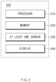
- FIG. 2 is a block diagram illustrating a configuration of a AR device.
- An AR device 200 may include a processor 210, a memory 220, at least one sensor 230, and/or a display 240.
- the configuration of the AR device 200 of FIG. 2 is illustrative, and the AR device 200 may further include another component.
- the AR device 200 may further include a wireless communication circuit.
- the processor 210 may execute, for example, software (e.g., a program 140 of FIG. 1 ) to control at least one other component (e.g., a hardware or software component) of the AR device 200 connected with the processor 210 and may perform a variety of data processing and calculation.
- the processor 210 may store commands or data received from another component (e.g., the at least one sensor 230) in a volatile memory (e.g., 132 of FIG. 1 ), may process the commands or data stored in the volatile memory 132, and may store result data in a non-volatile memory (e.g., 134 of FIG. 1 ).
- the processor 210 may process calculation for providing AR.
- the processor 210 may process calculation for providing AR by dividing it with an external device (e.g., 101 of FIG. 1 ) (e.g., cloud computing).
- an external device e.g., 101 of FIG. 1
- the processor 210 may exchange data for providing AR with the external device through the wireless communication circuit.
- the external device may process calculation associated with data and may transmit the data to the AR device 200.
- the memory 220 may store various pieces of data used by at least one component (e.g., the processor 210 or the at least one sensor 230) of the AR device 200.
- the data may include, for example, input data or output data associated with software (e.g., a program 140 of FIG. 1 ) and a command associated with it.
- the memory 220 may include the volatile memory 132 or the non-volatile memory 134.
- the memory 200 may data for providing AR.
- the memory 220 may store data for AR elements mapped to an AR space.
- the at least one sensor 230 may sense an operation state (e.g., power) of the AR device 200 or an external environment state (e.g., a user state) and may generate an electrical signal or a data value corresponding to the sensed state.
- the at least one sensor 230 may include, for example, a gesture sensor, an acceleration sensor, a grip sensor, a proximity sensor, a color sensor, and/or a biometric sensor.
- the AR device 200 may detect an operation of a user using the at least one sensor 230 and may provide AR based on the operation of the user.
- the display 240 may visually provide information to the outside (e.g., the user) of the AR device 200.
- the display 240 may be understood as a see-through display.
- the AR device 200 may output an AR element on the display 240.
- the user may see the AR element disposed on the AR space by means of the display 240.
- a space (or region) that the user is able to see by means of the display 240 of the AR device 200 in the AR space may be referred to as a user screen.
- the AR device 200 may provide the user with AR by means of the display 240.
- the AR may be understood as the case where the AR element is output on the AR space corresponding to the user screen.
- the AR device 200 may recognize an object and an environment of the AR space and may map an AR element corresponding to it to the recognized object or environment.
- the AR device 200 may store the mapping data in the memory 220.
- the AR device 200 may map an application (e.g., an image application) associated with the TV to the TV.
- the mapping data may be stored in the memory 220.
- the AR device 200 may receive mapping data for the AR space from a server (e.g., 108 of FIG. 1 ).
- mapping data for the AR space may be stored in the server (e.g., a cloud).
- the AR device 200 may receive mapping data from the server and may store the received mapping data in the memory 220.
- the AR device 200 may bring data from the memory 220 to output an AR element on the AR space.
- the AR device 200 may receive a user input (e.g., a gesture) to the AR element and may provide AR in response to the user input.
- the AR device 200 may output an application (e.g., the image application) on a specific object of the AR space and may receive a user input (e.g., a touch gesture) to run (e.g., play) the application (e.g., the image application).
- the AR device 200 may obtain data associated with an operation of the user (e.g., information associated with a movement direction of the user, a movement speed of the user, a gaze direction of the user, and/or a head direction of the user) using the at least one sensor 230.
- the operation of the user may be understood as the case where the user moves his or her body's part (e.g., a hand or a foot).
- the AR device 200 may recognize the operation of the user as a user input.
- the AR device 200 may recognize the operation of the user as a user input.
- the AR device 200 may execute the AR element (e.g., the application) in response to the user input.
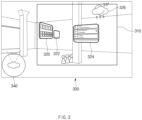
- FIG. 3 illustrates AR provided by an AR device.
- An AR space 300 of FIG. 3 may be understood as the case where the AR element is output on an object and an environment of a real space where a user and an AR device 200 are located.
- the AR device 200 may output AR elements 320, 322, 324, 326, and 340 on the AR space 300.
- the AR elements 320, 322, 324, 326, and 340 may be fixed at specified locations.
- the AR elements 320, 322, 324, 326, and 340 may be mapped to specific coordinates or objects (e.g., home appliances) in a real space.
- the AR elements 320, 322, 324, 326, and 340 may be displayed on a display (e.g., 240 of FIG. 2 ) in various forms. The forms where the AR elements 320, 322, 324, 326, and 340 are displayed will be described in detail in FIG. 4 .
- a size of a display 240 or a viewing angle of a user has a physical limit, the user may see only a portion of the AR space 300 by means of the AR device 200.
- the user may see a region corresponding to a field of view (FOV) region 310 by means of the AR device 200.
- a portion of the AR space 300 provided by means of the display 240 by the AR device 200 may be referred to as a user screen. The user needs to move his or her gaze to see an AR element capable of being displayed on the outside of the user screen.
- FIG. 3 illustrates the embodiment in which the AR element 340 indicating a gaze and a location of the user is output on the outside of the user screen.
- the AR element 340 may be output on the inside of the user screen.
- the AR element 340 indicating the gaze and the location of the user may fail to be output by the AR device 200.
- the AR element 340 may be output at a fixed location in the user screen.
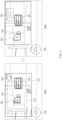
- FIG. 4 illustrates a method for displaying an AR element.
- an AR device may differently display AR elements 320, 322, 324, and 326 on a user screen depending on locations of the AR elements 320, 322, 324, and 326.
- the user screen may be referred to as AR that the user is able to see by means of a display (e.g., 240 of FIG. 2 ) of the AR device 200.
- a size of the user screen may be understood as corresponding to an FOV region (e.g., 310 of FIG. 3 ) of the user.
- the FOV region 310 may include a field of interest (FOI) region 410.
- the FOI region 410 may refer to a region which is smaller in size than the FOV region 310.
- the FOI region 410 may refer to a region that the user looks at with more interest in the FOV region 310.
- a size of the FOI region 410 may be adjusted.
- the AR device 200 may change an area of the FOI region 410 depending on user settings.
- the AR elements 320, 322, 324, and 326 may be displayed differently according to their locations in the user screen.
- the applications 320, 322, and 324 among the AR elements 320, 322, 324, and 326 may be located in the FOI region 410 and the application 326 may be located between the FOV region 310 and the FOI region 410.
- the AR device 200 may output the applications 320, 322, and 324 located in the FOI region 410 in the form of a preview and may output the application 326 located between the FOV region 310 and the FOI region 410 in the form of a widget.
- the preview may be understood as a user interface in which a function of the application is partially executed.
- the user may user a portion of a function (e.g., image playback) capable of being used when running an application (e.g., an image application) by means of the preview.
- a function e.g., image playback
- the widget may be understood as a user interface which briefly displays a function and/or content (weather information) of an application (e.g., a weather application).
- the AR elements 320, 322, 324, and 326 may be displayed differently.
- the user screen provided by the AR device 200 may be for a region more moved to the right than that in 400a.
- regions where the AR elements 320, 322, 324, and 326 are located in the user screen may vary.
- the applications 322, 324, and 326 may be located in the FOI region 410, and the application 320 may be located between the FOV region 310 and the FOI region 410.
- the AR device 200 may output the applications 322, 324, and 326 on the display 240 in the form of a preview and may output the application 320 on the display 240 in the form of a widget.
- the AR device 200 may display an AR element located on a region (i.e., the FOI region 410) that the user looks at with more interest differently from another AR element, thus increasing concentration on an application that the user wants to see.
- the AR device 200 may provide a user interface (UI) for assisting in identifying, executing, and/or navigating an AR element capable of being displayed on the AR space.
- UI user interface
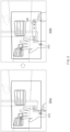
- FIG. 5 illustrates a user input in AR.
- An AR device may provide AR of FIGS. 2 to 4 by means of a display (e.g., 240 of FIG. 2 ).
- the AR device 200 may receive a user input to an AR element using at least one sensor (e.g., 230 of FIG. 2 ).
- the user input may be understood as various gestures using a body's part (e.g., a hand or a foot)
- the AR device 200 may recognize a body's part (e.g., a hand) of a user using the at least one sensor 230.
- the AR device 200 may recognize a body's part of the user and may output an AR element 510 capable of receiving an input of the user on the body's part of the user.
- an application 326 is located outside an FOV region (e.g., 310 of FIG. 3 ) in FIG. 5 , it may fail to be displayed on a user screen.
- the AR device 200 may receive a user input to the AR element 510.
- the user input may be referred to as a touch, swiping, and/or a double tap gesture of the user on the AR element 510.
- the description of the user input is illustrative, and the user input may include all gestures for selecting the AR element 510.
- the AR device 200 may output a user menu 520 in response to the user input in 500a.
- the user menu 520 may be understood as an AR element for outputting a user interface.
- the AR device 200 may receive a user input to the user menu 520 and may output a user interface described below.
- FIG. 5 is an example for describing the user input for outputting the user interface, and an embodiment of the disclosure is not limited thereto.
- the user input for outputting a user interface in 500a and 500b may be performed by one user input.
- the AR device 200 may receive a user input to an AR element (e.g., a shortcut key) output and may output a user interface.
- an AR element e.g., a shortcut key
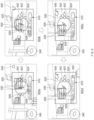
- FIG. 6 illustrates a user interface according to an embodiment.
- an AR device may receive a user input of FIG. 5 and may output a user interface 610.
- the user interface 610 may indicate types, relative locations, and/or directions of AR elements capable of being displayed on an AR space. 600a to 600d of FIG. 6 indicate the user interface 610 according to an embodiment.
- the user interface 610 may be provided in another method.
- the user interface 610 may include at least one graphic object 620, 622, 624, 626, and 628 and an indicator 630 (e.g., a compass shape) indicating a direction of the AR device 200.
- the AR device 200 may output the user interface 610 together on an AR space (e.g., 300 of FIG. 3 ).
- the at least one graphic object 620, 622, 624, 626, and 628 may correspond to AR elements (e.g., applications 320, 322, 324, and 326 of FIG. 3 ) capable of being displayed on the AR space.
- the at least one graphic object 620, 622, 624, 626, and 628 may indicate relative locations and/or directions of the AR elements respectively corresponding thereto.
- the graphic object 620 may correspond to an application 640, which may indicate a relation location and/or direction from a user of the application 640.
- the user, the graphic object 620, and the application 640 may be aligned in one direction on the user interface 610.
- the gaze and direction of the user in 660a may be displayed like an AR element 340 in 600a.
- the application 640 in 600a may be an AR element capable of being displayed on the outside of a user screen, which is not visible to the user.
- the AR device 200 may notify the user of a location and/or a direction of the application 640 by means of the user interface 610.
- the indicator 630 may be understood as indicating locations and gaze directions of the AR device 200 and the user in the AR space. For example, a direction indicated by one side of the indicator 630 and a direction that the user is looking at in the AR element 340 may be identical to each other. When the location and the gaze direction of the user is moved, the AR device 200 may display the indicator 630 in which it is reflected on the user interface 610.
- the AR device 200 may output the user interface 610 like 600b.
- the gaze direction of the user may be referenced by the AR element 340 in 600b.
- a description of the AR element 340 may be referenced by the description of FIG. 3 .
- the indicator 630 may interwork with gaze movement of the user to rotate such that its one side more indicates the right than that in 600a. The user may know that the gaze direction of the user moves in a direction where the application 640 is located by means of the user interface 610.
- the AR device 200 may output the user interface 610 like 600c.
- the gaze direction of the user may be referenced by the AR element 340 in 600c.
- the indicator 630 may interwork with gaze movement of the user to rotate such that its one side more indicate the right than that in 600b.
- the user may know that the gaze direction of the user is aligned with the direction where the application 640 is located by means of the user interface 610.
- the application 640 When at least a portion of the application 640 is located in an FOV region 310 due to the location and gaze movement of the user, it may be displayed on a user screen.
- the AR device 200 may provide an AR element 650 for ending the user interface 610.
- the AR device 200 may receive the user input to the AR element 650 to remove the user interface 610 and may provide AR.
- the AR device 200 may provide the user interface 610 to assist the user to easily identify the relative location and direction of the AR element capable of being displayed on the AR space.
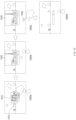
- FIG. 7 illustrates a user interface according to an embodiment.
- 700a illustrates that an AR device 200 receives a user input of FIG. 5 .
- a description of 700a may be referenced by the description of FIG. 5 .
- the AR device 200 may output a user interface 710 in 700b in response to a user input.
- the user interface 710 may include at least one graphic object 720, 722, 724, and 726 and a bar object 730.
- the at least one graphic object 720, 722, 724, and 726 may correspond to AR elements 740, 742, 744, and 746, respectively.
- the at least one graphic object 720, 722, 724, and 726 may indicate relative locations and directions of the corresponding AR elements 740, 742, 744, and 746 on the bar object 730.
- the at least one graphic object 720, 722, 724, and 726 may be displayed at the same size on the bar object 730, irrespective of distances between the corresponding AR elements 740, 742, 744, and 746 and a user. For example, because the application 722 is located in a place relatively closer to the user than the application 724, it may appear larger to the user. However, the graphic objects 622 and 624 corresponding to them may be displayed at the same size on the bar object 730.
- the AR device 200 may output the user interface 710 like 700c.
- the bar object 730 may interwork with the gaze movement of the user to rotate to the right.
- a new application 748 may be displayed on the user screen.
- the AR device 200 may display a graphic object 728 corresponding to the new application 748 on the bar object 730.
- 700d illustrates a user input ending the user interface 710.
- the AR device 200 may provide an AR element 750 for ending the user interface 710.
- the AR device 200 may receive a user input to the AR element 750.
- a description of the user input may be referenced by the description of FIG. 5 .
- the AR device 200 may remove the user interface 710 in response to the user input and may provide AR such as 700e.
- FIG. 8 illustrates a user interface according to an embodiment.
- a user interface 710 may include at least one graphic object 720, 722, 724, and 726 and a bar object 730. Unlike FIG. 7 , the user interface 710 of FIG. 8 may be manipulated by a user gesture (e.g., grab & release).
- a user gesture e.g., grab & release
- an AR device 200 may receive a user input and may manipulate the user interface 710. For example, a user may perform a grab operation using his or her body's part (e.g., a hand) with respect to a predetermined region of the user interface 710. After the grab operation, the user may move the body's part (e.g., the hand) to the left or right to rotate the bar object 730. When the user moves the body's part (e.g., the hand) in the state where he or she grabs the bar object 730, the bar object 730 in 800b may rotate in a counterclockwise direction like 800c.
- a user may perform a grab operation using his or her body's part (e.g., a hand) with respect to a predetermined region of the user interface 710. After the grab operation, the user may move the body's part (e.g., the hand) to the left or right to rotate the bar object 730.
- the bar object 730 in 800b may rotate in a counterclockwise direction like 800c
- the at least one graphic object 720, 722, 724, and 726 displayed on the bar object 730 may be displayed at a location where it rotates together with the bar object 730.
- AR may be provided irrespective of the user input.
- AR elements 740, 742, 744, and 746 may be displayed at fixed locations.
- the user may manipulate only the bar object 730 and may identify an AR element capable of being displayed on an AR space irrespective of the gaze of the user.
- the at least one graphic object 720, 722, 724, 726, and 728 may fail to be aligned with AR elements 740, 742, 744, 746, and 748 respectively corresponding thereto.
- the AR device 200 may receive a user input and may fix the bar object 730 in a rotated state.
- the user input in 800d may be understood as a release operation of releasing the grab.
- FIG. 9 illustrates a navigating function provided by an AR device.
- an AR device e.g., 200 of FIG. 2
- the AR device 200 may receive a user input to the user menu 910 and may perform a navigating function.
- the user input may be referred to as an operation where a user selects a navigate object 915 using his or her body's part (e.g., a hand).
- the user input to the navigate object 915 may include a user input selecting a target application 930 which becomes a navigating target.
- a navigating function will be described in 900b to 990i.
- the AR device 200 may output an indicator 920 (e.g., an arrow) indicating a relative location and direction of the target application 930.
- the user may identify the relative location and direction of the target application 930 by means of a direction indicated by the indicator 920.
- the user may move in a direction and location indicated by the indicator 920.
- the indicator 920 indicates the left in 900c
- the user may move to the left along the indicator 920.
- the target application 930 may be located in a user screen.
- the AR device 200 may perform a separate indication to indicate that a specific application displayed on the user screen is the target application 930.
- the AR device 200 may further display a quadrangular shape surrounding the target application 930.
- the user may move in a direction where the target application 930 is located along the indicator 920.
- the AR device 200 may differently output a shape of the indicator 920.
- the AR device 200 may receive a user input to an AR element 940.
- the AR device 200 may end the navigating function in response to the user input and may provide AR.
- the target application 930 may be displayed in the form of a preview or a widget on the user screen.
- the user may identify an AR element capable of being displayed on the AR space using the navigation function of FIG. 9 and may easily move to a place where the target application 930 is located.
- FIG. 10 illustrates a bringing function provided by an AR device.
- an AR device e.g., 200 of FIG. 2
- the AR device 200 may receive a user input to the user menu 1010 and may perform a bringing function.
- the user input may be referred to as an operation where a user selects a bring to me object 1015 using his or her body's part (e.g., a hand).
- the user input to the bring to me object 1015 may include a user input selecting a target application which becomes a bringing target.
- a bringing function will be described in 1000b to 1000d.
- the AR device 200 may bring a target application 1020 to a user screen.
- the target application 1020 may be displayed or run as a preview.
- the AR device 200 may receive a user input to an AR element 1040.
- the AR device 200 may end the bringing function in response to the user input.
- the user may identify an AR element located outside the user screen, using the bringing function of FIG. 10 , and may display or execute the target application 1020 on the user screen.
- FIG. 11 illustrates a flowchart of a method for providing a user interface.
- an AR device may provide a user with AR by means of a display (e.g., 240 of FIG. 2 ).
- the AR may be understood as outputting an AR element on an object and/or an environment located in an AR space (e.g., 300 of FIG. 3 ).
- the user may see AR corresponding to an FOV region (e.g., 310 of FIG. 3 ) by means of the AR device 200.
- a user screen may be referred to as AR that user is able of see by means of the display 240.
- the FOV region 310 may include an FOI region (e.g., 410 of FIG. 4 ).
- the AR element may be displayed differently according to its location in the FOV region 310.
- the AR element located in the FOI region 410 may be displayed in the form of a preview.
- the AR element located between the FOI region 410 and the FOV region 310 may be displayed in the form of a widget. Because the region that the user is able to see by means of the AR device 200 is limited, the user needs to identify a location and a direction of an AR element located outside the user screen.
- the AR device 200 may receive a user input (e.g., a gesture) to the AR element.
- the user input may be performed in various methods. A description of the user input may be referenced by the description of FIG. 5 .
- the user input in operation 1110 may be understood as a user input for outputting a user interface.
- the user input in operation 1110 may include one or more user inputs until the AR device 200 outputs the user interface.
- the AR device 200 may receive a user input and may display a user interface on the display 240.
- a description of the user interface may be referenced by the description of FIGS. 6 to 8 .
- the user interface may indicate relative locations and directions of AR elements capable of being displayed on an AR space.
- the user may identify the relative locations and directions of the AR elements capable of being displayed on the AR space by means of the user interface.
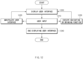
- FIG. 12 illustrates a flowchart of various user inputs to a user interface.
- an AR device e.g., 200 of FIG. 2
- the AR device 200 may receive a user input to the user interface.
- the user input in operation 1210 may be performed for various purposes.
- the AR device 200 may receive a user input and may proceed to operation 1220.
- the user may manipulate the user interface by means of the user input.
- the AR device 200 may display the user interface manipulated in response to the user input.
- the user input may be referred to as gaze movement of the user.
- the user input may be referred to as a grab & release operation of the user.
- the user may manipulate the user interface and may more easily identify relative locations and directions of AR elements capable of being displayed on an AR space.
- the AR device 200 may receive a user input and may proceed to operation 1230.
- the user input in operation 1230 may be understood as a user input for executing a navigating or bringing function.
- the AR device 200 may receive a user input (e.g., a touch gesture) to a navigating object (e.g., 915 of FIG. 9 ) or a bringing object (e.g., 1015 of FIG. 10 ) in a user menu (e.g., 910 of FIG. 9 or 1010 of FIG. 10 ).
- the user input may include a user input selecting a target application (e.g., 930 of FIG. 9 ).
- the AR device 200 may notify the user of a location and direction of the target application using an indicator (e.g., 920 of FIG. 9 ) or may bring the target application to a user screen to display or execute the target application as a preview.
- the user may navigate an AR element outside the user screen or may bring the AR element to the user screen, by means of the navigating or bringing function.
- the AR device 200 may receive a user input to an AR element (e.g., 940 of FIG. 9 or 1040 of FIG. 10 ) for ending the navigating or bringing function to end the navigating or bringing function and may display a user interface.
- the AR device 200 may receive a user input for ending the user interface.
- the AR device 200 may proceed to operation 1240 in response to the user input.
- the AR device 200 may remove the user interface and may provide AR for an AR space (e.g., 300 of FIG. 3 ).
Landscapes
- Engineering & Computer Science (AREA)
- Theoretical Computer Science (AREA)
- General Engineering & Computer Science (AREA)
- Physics & Mathematics (AREA)
- General Physics & Mathematics (AREA)
- Human Computer Interaction (AREA)
- Software Systems (AREA)
- Computer Graphics (AREA)
- Computer Hardware Design (AREA)
- Computer Vision & Pattern Recognition (AREA)
- Radar, Positioning & Navigation (AREA)
- Remote Sensing (AREA)
- Computing Systems (AREA)
- Architecture (AREA)
- Databases & Information Systems (AREA)
- Evolutionary Computation (AREA)
- General Health & Medical Sciences (AREA)
- Medical Informatics (AREA)
- Multimedia (AREA)
- Artificial Intelligence (AREA)
- Health & Medical Sciences (AREA)
- User Interface Of Digital Computer (AREA)
- Processing Or Creating Images (AREA)
Priority Applications (1)
| Application Number | Priority Date | Filing Date | Title |
|---|---|---|---|
| EP25193971.6A EP4617843A3 (de) | 2020-07-01 | 2021-06-21 | Elektronische vorrichtung und verfahren zur bereitstellung von erweiterter realität |
Applications Claiming Priority (2)
| Application Number | Priority Date | Filing Date | Title |
|---|---|---|---|
| KR1020200080848A KR102734523B1 (ko) | 2020-07-01 | 2020-07-01 | 증강 현실을 제공하는 전자 장치 및 그 방법 |
| PCT/KR2021/007733 WO2022005075A1 (ko) | 2020-07-01 | 2021-06-21 | 증강 현실을 제공하는 전자 장치 및 그 방법 |
Related Child Applications (1)
| Application Number | Title | Priority Date | Filing Date |
|---|---|---|---|
| EP25193971.6A Division EP4617843A3 (de) | 2020-07-01 | 2021-06-21 | Elektronische vorrichtung und verfahren zur bereitstellung von erweiterter realität |
Publications (2)
| Publication Number | Publication Date |
|---|---|
| EP4167191A1 true EP4167191A1 (de) | 2023-04-19 |
| EP4167191A4 EP4167191A4 (de) | 2023-11-22 |
Family
ID=79316481
Family Applications (2)
| Application Number | Title | Priority Date | Filing Date |
|---|---|---|---|
| EP21834394.5A Pending EP4167191A4 (de) | 2020-07-01 | 2021-06-21 | Elektronische vorrichtung und verfahren zur bereitstellung von erweiterter realität |
| EP25193971.6A Pending EP4617843A3 (de) | 2020-07-01 | 2021-06-21 | Elektronische vorrichtung und verfahren zur bereitstellung von erweiterter realität |
Family Applications After (1)
| Application Number | Title | Priority Date | Filing Date |
|---|---|---|---|
| EP25193971.6A Pending EP4617843A3 (de) | 2020-07-01 | 2021-06-21 | Elektronische vorrichtung und verfahren zur bereitstellung von erweiterter realität |
Country Status (4)
| Country | Link |
|---|---|
| US (1) | US12602881B2 (de) |
| EP (2) | EP4167191A4 (de) |
| KR (2) | KR102734523B1 (de) |
| WO (1) | WO2022005075A1 (de) |
Families Citing this family (3)
| Publication number | Priority date | Publication date | Assignee | Title |
|---|---|---|---|---|
| EP4521203A4 (de) | 2022-08-29 | 2025-08-06 | Samsung Electronics Co Ltd | Elektronische vorrichtung zur steuerung einer wearable-vorrichtung auf basis der eingabe durch eine elektronische vorrichtung und verfahren dafür |
| WO2024123041A1 (ko) * | 2022-12-06 | 2024-06-13 | 삼성전자 주식회사 | 웨어러블 장치의 움직임에 따라 가상 객체의 표시 상태를 조정하는 웨어러블 장치 및 그 제어 방법 |
| CN120283217A (zh) * | 2022-12-20 | 2025-07-08 | 三星电子株式会社 | 用于显示视觉对象的可穿戴设备及其方法 |
Family Cites Families (32)
| Publication number | Priority date | Publication date | Assignee | Title |
|---|---|---|---|---|
| US8745541B2 (en) * | 2003-03-25 | 2014-06-03 | Microsoft Corporation | Architecture for controlling a computer using hand gestures |
| US7873708B2 (en) * | 2004-04-28 | 2011-01-18 | At&T Mobility Ii Llc | Systems and methods for providing mobile advertising and directory assistance services |
| US8341541B2 (en) | 2005-01-18 | 2012-12-25 | Microsoft Corporation | System and method for visually browsing of open windows |
| DE102009037835B4 (de) | 2009-08-18 | 2012-12-06 | Metaio Gmbh | Verfahren zur Darstellung von virtueller Information in einer realen Umgebung |
| EP2393056A1 (de) * | 2010-06-02 | 2011-12-07 | Layar B.V. | Erfassung, Klassifizierung und Anzeige von Interessenpunkten zur Verwendung in einem Dienstleistungsbereitstellungssystem für erhöhte Realität und grafische Benutzeroberfläche zur Anzeige solcher klassifizierten Interessenpunkte |
| US9977496B2 (en) * | 2010-07-23 | 2018-05-22 | Telepatheye Inc. | Eye-wearable device user interface and augmented reality method |
| CN103210364B (zh) * | 2010-09-24 | 2017-03-15 | 夏普株式会社 | 内容显示装置、内容显示方法、便携终端、程序以及记录介质 |
| WO2013023706A1 (en) * | 2011-08-18 | 2013-02-21 | Layar B.V. | Computer-vision based augmented reality system |
| KR102021050B1 (ko) | 2012-06-06 | 2019-09-11 | 삼성전자주식회사 | 내비게이션 정보를 제공하는 방법, 기계로 읽을 수 있는 저장 매체, 이동 단말 및 서버 |
| US9129430B2 (en) * | 2013-06-25 | 2015-09-08 | Microsoft Technology Licensing, Llc | Indicating out-of-view augmented reality images |
| JP2015149634A (ja) | 2014-02-07 | 2015-08-20 | ソニー株式会社 | 画像表示装置および方法 |
| KR102303115B1 (ko) * | 2014-06-05 | 2021-09-16 | 삼성전자 주식회사 | 웨어러블 디바이스 및 웨어러블 디바이스 의 증강 현실 정보 제공 방법 |
| US20160054791A1 (en) * | 2014-08-25 | 2016-02-25 | Daqri, Llc | Navigating augmented reality content with a watch |
| JP6549693B2 (ja) | 2015-02-25 | 2019-07-24 | 京セラ株式会社 | ウェアラブル装置、制御方法及び制御プログラム |
| KR102317247B1 (ko) * | 2015-06-15 | 2021-10-26 | 한국전자통신연구원 | 영상정보를 이용한 증강현실 기반 손 인터랙션 장치 및 방법 |
| US20170092002A1 (en) * | 2015-09-30 | 2017-03-30 | Daqri, Llc | User interface for augmented reality system |
| CN113220116A (zh) | 2015-10-20 | 2021-08-06 | 奇跃公司 | 改变可穿戴设备用户输入模式的系统和方法及可穿戴系统 |
| WO2017098822A1 (ja) * | 2015-12-10 | 2017-06-15 | ソニー株式会社 | 情報処理装置、情報処理方法、及びプログラム |
| JP6560974B2 (ja) | 2015-12-17 | 2019-08-14 | 株式会社ソニー・インタラクティブエンタテインメント | 情報処理装置および操作受付方法 |
| JP6518582B2 (ja) * | 2015-12-21 | 2019-05-22 | 株式会社ソニー・インタラクティブエンタテインメント | 情報処理装置および操作受付方法 |
| KR20170126295A (ko) | 2016-05-09 | 2017-11-17 | 엘지전자 주식회사 | 헤드 마운티드 디스플레이 장치 및 그것의 제어방법 |
| KR102632795B1 (ko) * | 2016-09-21 | 2024-02-02 | 삼성전자주식회사 | 컨텐츠와 연관된 네비게이터 표시 방법 및 이를 구현한 전자 장치 |
| US20180095635A1 (en) * | 2016-10-04 | 2018-04-05 | Facebook, Inc. | Controls and Interfaces for User Interactions in Virtual Spaces |
| US10182210B1 (en) * | 2016-12-15 | 2019-01-15 | Steelcase Inc. | Systems and methods for implementing augmented reality and/or virtual reality |
| KR102330829B1 (ko) | 2017-03-27 | 2021-11-24 | 삼성전자주식회사 | 전자 장치에서 증강현실 기능 제공 방법 및 장치 |
| KR102108962B1 (ko) | 2017-08-08 | 2020-05-12 | 한국과학기술연구원 | 전방향 가상현실 네비게이션을 위한 제자리 걸음을 이용한 인터랙션 장치 및 방법 |
| WO2019165055A1 (en) * | 2018-02-22 | 2019-08-29 | Magic Leap, Inc. | Browser for mixed reality systems |
| US12093518B2 (en) * | 2018-11-15 | 2024-09-17 | Spintura, Inc. | Electronic picture carousel |
| US10602302B1 (en) * | 2019-02-06 | 2020-03-24 | Philip Scott Lyren | Displaying a location of binaural sound outside a field of view |
| US11151967B2 (en) * | 2019-06-06 | 2021-10-19 | Honeywell International Inc. | Method and system for spawning attention pointers (ATP) for drawing attention of an user in a virtual screen display with augmented and virtual reality |
| US11714890B2 (en) * | 2020-04-16 | 2023-08-01 | Capital One Services, Llc | Systems and methods for authenticating users |
| CN116489268A (zh) * | 2020-08-05 | 2023-07-25 | 华为技术有限公司 | 一种设备识别方法及相关装置 |
-
2020
- 2020-07-01 KR KR1020200080848A patent/KR102734523B1/ko active Active
-
2021
- 2021-06-21 WO PCT/KR2021/007733 patent/WO2022005075A1/ko not_active Ceased
- 2021-06-21 EP EP21834394.5A patent/EP4167191A4/de active Pending
- 2021-06-21 EP EP25193971.6A patent/EP4617843A3/de active Pending
-
2022
- 2022-12-23 US US18/146,257 patent/US12602881B2/en active Active
-
2024
- 2024-11-21 KR KR1020240167194A patent/KR20240168285A/ko active Pending
Also Published As
| Publication number | Publication date |
|---|---|
| US20230128520A1 (en) | 2023-04-27 |
| WO2022005075A1 (ko) | 2022-01-06 |
| EP4617843A3 (de) | 2025-11-19 |
| EP4617843A2 (de) | 2025-09-17 |
| US12602881B2 (en) | 2026-04-14 |
| KR102734523B1 (ko) | 2024-11-27 |
| EP4167191A4 (de) | 2023-11-22 |
| KR20240168285A (ko) | 2024-11-29 |
| KR20220003254A (ko) | 2022-01-10 |
Similar Documents
| Publication | Publication Date | Title |
|---|---|---|
| EP3665559B1 (de) | Elektronische vorrichtung und verfahren zur ausführung einer funktion unter verwendung einer eingabeschnittstelle, die über mindestens einen teil des inhalts angezeigt wird | |
| US12602881B2 (en) | Electronic device and method for providing augmented reality | |
| US20240281126A1 (en) | Electronic device changing configuration of screen according to change in size of at least one icon and method for controlling the same | |
| US11941315B2 (en) | Wearable electronic device for displaying augmented reality object and method for operating the same | |
| US11822728B2 (en) | Electronic device and operation method thereof | |
| US20230260177A1 (en) | Electronic device and method for providing augmented reality content | |
| US20250217091A1 (en) | Electronic device and method for controlling screen displayed on flexible display | |
| EP4325345A1 (de) | Elektronische vorrichtung zur erfassung von benutzereingaben über eine virtuelle tastatur und betriebsverfahren dafür | |
| US12086373B2 (en) | Electronic device and method for controlling display of a plurality of objects on wearable display device | |
| EP4261790B1 (de) | Verfahren zur bereitstellung einer inhaltserzeugungsfunktion und elektronische vorrichtung zur unterstützung davon | |
| EP4651068A1 (de) | Elektronische vorrichtung zur bereitstellung von leistungsinhalt in virtueller realität und steuerungsverfahren dafür | |
| EP4394568A1 (de) | Verfahren zur anzeige eines ausführungsbildschirms einer anwendung und elektronische vorrichtung zur unterstützung davon | |
| EP3687186B1 (de) | Vorrichtung und verfahren zur bereitstellung von informationen über interessenpunkte (poi) in 360-grad-videos | |
| US12489880B2 (en) | Electronic device for providing AR/VR environment, and operation method thereof | |
| EP4379534A1 (de) | Elektronische vorrichtung zur steuerung der anzeige einer virtuellen vorrichtung, verfahren dafür und nichttransitorisches computerlesbares speichermedium dafür | |
| EP4589416A1 (de) | Elektronische vorrichtung, die die konfiguration eines bildschirms als reaktion auf die änderung der grösse von mindestens einem symbol ändert, und steuerungsverfahren dafür | |
| US20240419320A1 (en) | Electronic device and method for displaying touch input or hovering input on basis of change in display area of rollable display | |
| EP4597284A1 (de) | Elektronische vorrichtung zur bereitstellung eines repräsentativen bildes einer externen elektronischen vorrichtung, verfahren zum betrieb davon und speichermedium | |
| EP4603955A1 (de) | Verfahren zur bereitstellung einer benutzerschnittstelle und elektronische wearable-vorrichtung zur unterstützung davon | |
| US20250124627A1 (en) | First electronic device including artificial intelligence model, method for operating the same, and second electronic device including artificial intelligence model | |
| EP4554198A1 (de) | Elektronische vorrichtung und verfahren zur anzeige eines bildschirms durch mehrere anzeigen | |
| US20260023480A1 (en) | Electronic device for controlling display of execution screens, operation method thereof, and recording medium | |
| US20260064238A1 (en) | Head-wearable electronic device, method, and non-transitory computer-readable storage medium for touch input in three-dimensional space | |
| EP4538841A1 (de) | Elektronische vorrichtung zur unterstützung von paarung und steuerungsverfahren dafür | |
| EP4730094A1 (de) | Elektronische vorrichtung und verfahren zur verwaltung eines popup-fensters damit |
Legal Events
| Date | Code | Title | Description |
|---|---|---|---|
| STAA | Information on the status of an ep patent application or granted ep patent |
Free format text: STATUS: THE INTERNATIONAL PUBLICATION HAS BEEN MADE |
|
| PUAI | Public reference made under article 153(3) epc to a published international application that has entered the european phase |
Free format text: ORIGINAL CODE: 0009012 |
|
| STAA | Information on the status of an ep patent application or granted ep patent |
Free format text: STATUS: REQUEST FOR EXAMINATION WAS MADE |
|
| 17P | Request for examination filed |
Effective date: 20230111 |
|
| AK | Designated contracting states |
Kind code of ref document: A1 Designated state(s): AL AT BE BG CH CY CZ DE DK EE ES FI FR GB GR HR HU IE IS IT LI LT LU LV MC MK MT NL NO PL PT RO RS SE SI SK SM TR |
|
| DAV | Request for validation of the european patent (deleted) | ||
| DAX | Request for extension of the european patent (deleted) | ||
| A4 | Supplementary search report drawn up and despatched |
Effective date: 20231025 |
|
| RIC1 | Information provided on ipc code assigned before grant |
Ipc: G06F 3/04842 20220101ALI20231019BHEP Ipc: G06F 3/04817 20220101ALI20231019BHEP Ipc: G06F 3/04815 20220101ALI20231019BHEP Ipc: G06F 3/0482 20130101ALI20231019BHEP Ipc: G06F 3/0481 20220101ALI20231019BHEP Ipc: G06F 3/01 20060101ALI20231019BHEP Ipc: G06T 19/00 20110101AFI20231019BHEP |
|
| STAA | Information on the status of an ep patent application or granted ep patent |
Free format text: STATUS: EXAMINATION IS IN PROGRESS |
|
| 17Q | First examination report despatched |
Effective date: 20241209 |