EP4167251B1 - Noyau pour opération de suivi de charge - Google Patents
Noyau pour opération de suivi de charge Download PDFInfo
- Publication number
- EP4167251B1 EP4167251B1 EP21821656.2A EP21821656A EP4167251B1 EP 4167251 B1 EP4167251 B1 EP 4167251B1 EP 21821656 A EP21821656 A EP 21821656A EP 4167251 B1 EP4167251 B1 EP 4167251B1
- Authority
- EP
- European Patent Office
- Prior art keywords
- load
- reactor core
- control rod
- axial offset
- power
- Prior art date
- Legal status (The legal status is an assumption and is not a legal conclusion. Google has not performed a legal analysis and makes no representation as to the accuracy of the status listed.)
- Active
Links
Images


Classifications
-
- G—PHYSICS
- G21—NUCLEAR PHYSICS; NUCLEAR ENGINEERING
- G21C—NUCLEAR REACTORS
- G21C7/00—Control of nuclear reaction
- G21C7/06—Control of nuclear reaction by application of neutron-absorbing material, i.e. material with absorption cross-section very much in excess of reflection cross-section
- G21C7/08—Control of nuclear reaction by application of neutron-absorbing material, i.e. material with absorption cross-section very much in excess of reflection cross-section by displacement of solid control elements, e.g. control rods
- G21C7/10—Construction of control elements
-
- G—PHYSICS
- G21—NUCLEAR PHYSICS; NUCLEAR ENGINEERING
- G21C—NUCLEAR REACTORS
- G21C7/00—Control of nuclear reaction
- G21C7/06—Control of nuclear reaction by application of neutron-absorbing material, i.e. material with absorption cross-section very much in excess of reflection cross-section
- G21C7/08—Control of nuclear reaction by application of neutron-absorbing material, i.e. material with absorption cross-section very much in excess of reflection cross-section by displacement of solid control elements, e.g. control rods
-
- G—PHYSICS
- G21—NUCLEAR PHYSICS; NUCLEAR ENGINEERING
- G21D—NUCLEAR POWER PLANT
- G21D3/00—Control of nuclear power plant
- G21D3/08—Regulation of any parameters in the plant
-
- G—PHYSICS
- G21—NUCLEAR PHYSICS; NUCLEAR ENGINEERING
- G21D—NUCLEAR POWER PLANT
- G21D3/00—Control of nuclear power plant
- G21D3/08—Regulation of any parameters in the plant
- G21D3/12—Regulation of any parameters in the plant by adjustment of the reactor in response only to changes in engine demand
- G21D3/16—Varying reactivity
-
- Y—GENERAL TAGGING OF NEW TECHNOLOGICAL DEVELOPMENTS; GENERAL TAGGING OF CROSS-SECTIONAL TECHNOLOGIES SPANNING OVER SEVERAL SECTIONS OF THE IPC; TECHNICAL SUBJECTS COVERED BY FORMER USPC CROSS-REFERENCE ART COLLECTIONS [XRACs] AND DIGESTS
- Y02—TECHNOLOGIES OR APPLICATIONS FOR MITIGATION OR ADAPTATION AGAINST CLIMATE CHANGE
- Y02E—REDUCTION OF GREENHOUSE GAS [GHG] EMISSIONS, RELATED TO ENERGY GENERATION, TRANSMISSION OR DISTRIBUTION
- Y02E30/00—Energy generation of nuclear origin
- Y02E30/30—Nuclear fission reactors
Definitions
- the present disclosure relates to a reactor core for load following operation.
- a reactor core for load following operation of the conventional nuclear power plant performed a load following operation by raising and lowering control rods for a load following operation in an axial direction of the reactor core in response to set power (e.g., 50% to 100%).
- Van Geemert Rene et al. discusses the merits of Generalized Perturbation Theory (GPT) in the computational nuclear science and engineering context.
- Document KR 101668088 B1 discloses a control rod and a control rod assembly of a nuclear reactor.
- Document JPS58105088A discloses a control rod for a boiling water reactor, and more particularly a control rod capable of optimally controlling a power distribution of a reactor by specifying a distribution of a neutron absorber.
- Document " Improvement of the axial power distribution control capabilities in VVER-1000 reactors" (ANNALS OF NUCLEAR ENERGY, PERGAMON PRESS, OXFORD, GB, vol. 27, no.
- the present invention has been made in an effort to provide a reactor core for load following operation having advantages of minimizing fluctuations in power axial offset and xenon axial offset during a load following operation of a nuclear power plant.
- An exemplary embodiment of the present invention provides a reactor core for load following operation including: a reactor core body; a plurality of load-following control rods that are configured to be inserted into the reactor core body in an axial direction in response to an output set for the load following operation, overlap each other in the axial direction, and are configured to be simultaneously raised and lowered; and a first power axial offset control rod that is spaced apart from the plurality of load-following control rods in a plane, has an end portion positioned below a center of the reactor core body in the axial direction, and is configured to be raised and lowered only below the center of the reactor core body in a direction to compensate for a fluctuation in a power axial offset due to the insertion of the plurality of load-following control rods.
- the first power axial offset control rod may include: a top absorbing material having a first diameter; a bottom absorbing material that is positioned below the top absorbing material and has a second diameter larger than the first diameter; and a cladding material that encloses the top absorbing material and the bottom absorbing material, and a top thickness of the cladding material enclosing the top absorbing material is thicker than a bottom thickness of the cladding material enclosing the bottom absorbing material.
- the top absorbing material and the bottom absorbing material may contain an Ag-In-Cd alloy.
- the plurality of load-following control rods may include a first load-following control rod, a second load-following control rod, and a third load-following control rod sequentially overlapped by 30% to 70% in the axial direction.
- the first load-following control rod and the second load-following control rod may have the same structure as the first power axial offset control rod, and the third load-following control rod may have a structure different from that of the first power axial offset control rod.
- the reactor core may further include: a second power axial offset control rod that is spaced apart from the first power axial offset control rod, has an end portion positioned on a top of the reactor core body in the axial direction, and is configured to be raised and lowered only on the top of the reactor core body in a direction to assist the first power axial offset control rod.
- a second power axial offset control rod that is spaced apart from the first power axial offset control rod, has an end portion positioned on a top of the reactor core body in the axial direction, and is configured to be raised and lowered only on the top of the reactor core body in a direction to assist the first power axial offset control rod.
- the second power axial offset control rod may have a structure different from that of the first power axial offset control rod.
- the reactor core may further include: a plurality of shutdown control rods that are spaced apart from the plurality of load-following control rods in a plane, and inserted into the reactor core body for shutdown of a reactor.
- the power axial offset may have a negative value for an entire period
- the reactor core body may include a plurality of fuels including at least one of MOX and UO 2 .
- a reactor core for load following operation capable of minimizing fluctuations in power axial offset and xenon axial offset during a load following operation of a nuclear power plant. That is, according to a reactor core for load following operation according to an embodiment, it is possible to secure a sufficient thermal margin during a load following operation, thereby providing a much greater operating margin than before.
- the reactor core for load following operation may be a reactor core included in a pressurized water reactor (PWR), but is not limited thereto.
- PWR pressurized water reactor
- FIG. 1 is a layout diagram of a reactor core for load following operation according to an embodiment.
- FIG. 1 is a layout diagram illustrating a part of the entire reactor core.
- a reactor core for load following operation includes a reactor core body RC, a plurality of load-following control rods CY, CX, and C1, a first power axial offset control rod CZ, a second power axial offset control rod AO, and a plurality of shutdown control rods SB and SA.
- the reactor core body RC includes a plurality of fuel assemblies including at least one of MOX and UO 2 .
- the plurality of fuel assemblies includes a total of 193 assemblies, and one fuel assembly includes nuclear fuel rods in a 17*17 Westinghouse type arrangement.
- An effective reactor core length of the reactor core body RC may be 426.7 cm or 46 cm longer than the APR1400, but is not limited thereto.
- the fuel assemblies included in the reactor core body RC include fresh UO 2 fuel, once burned UO 2 fuel, twice burned UO 2 fuel, fresh MOX fuel, once burned MOX fuel, and twice burned MOX fuel.
- the arrangement of the fuel assemblies may be configured as illustrated in FIG. 1 , but is not limited thereto.
- the reactor core body RC may be operated for 18 months, but is not limited thereto.
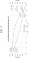
- FIG. 2 is a graph showing characteristics of a reactor core body illustrated in FIG. 1 .
- the X axis represents burnup (B/U)
- the left Y axis represents critical boron concentration (CBC)
- the right Y axis represents the power axial offset (power AO).
- the reactor core body may represent a beginning of cycle (BOC), a middle of cycle (MOC), and an end of the cycle (EOC), respectively, at each burnup of 0.1GWD/tHM, 14.3GWD/tHM, and 16.5GWD/tHM.
- BOC beginning of cycle
- MOC middle of cycle
- EOC end of the cycle
- the critical boron concentration (CBC) and the power axial offset (power AO) in each cycle are as illustrated in FIG. 2 .
- the power axial offset may have a negative value during the entire period, but is not limited thereto.
- PAO power axial offset
- P top means a top output of the reactor core
- P bottom means a bottom output of the reactor core
- the power axial offset (Power AO) of the reactor core body has a negative value, it means that the bottom output of the reactor core body is higher than the top output.
- the plurality of load-following control rods CY, CX, and C1 are arranged on a top of the reactor core body RC, and are optionally inserted into the reactor core body RC in the axial direction for load following operation control, power axial offset control, or reactor shutdown of the reactor core body RC.
- Control rods including the plurality of load-following control rods CY, CX, and C1, the first power axial offset control rod CZ, the second power axial offset control rod AO, and the plurality of shutdown control rods SB and SA include a total of 85 control rods, and 65 control rods of the control rods are positioned on UO 2 fuel assemblies, and 20 control rods are positioned on MOX fuel assemblies.
- FIG. 3 is a table showing characteristics of control rods illustrated in FIG. 1 .
- the plurality of load-following control rods CY, CX, and C1 are inserted into the reactor core body RC in the axial direction for reactivity control corresponding to the output set for the load following operation, and are simultaneously raised and lowered to the reactor core body RC by overlapping each other in the axial direction.
- the plurality of load-following control rods CY, CX, and C1 includes a first load-following control rod CY, a second load-following control rod CX, and a third load-following control rod C1.
- the first load-following control rod CY and the second load-following control rod CX have the same structure as the first power axial offset control rod CZ to be described later.
- the third load-following control rod C1 has a structure different from that of the first power axial offset control rod CZ.
- the third load-following control rod C1 includes an absorbing material containing B 4 C, and a top absorbing material and a bottom absorbing material have the same diameter.
- the first power axial offset control rod CZ is spaced apart from the plurality of load-following control rods CY, CX, and C1 in a plane for the power axial offset control during the load following operation, has an end portion inserted below the center of the reactor core body RC in the axial direction, and is lowered and raised only below the center of the reactor core body RC in the direction (i.e., direction in which the first power axial offset control rod CZ is raised when the top is over-output and is lowered when the bottom is over-output) to compensate for the fluctuation in the power axial offset due to the insertion of the plurality of load-following control rods CY, CX, and C1.
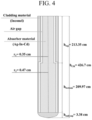
- FIG. 4 is a longitudinal cross-sectional view illustrating the first power axial offset control rod illustrated in FIG. 1 .
- the first power axial offset control rod CZ includes an absorbing material containing a silver-indium-cadmium (Ag-In-Cd) alloy.
- the first power axial offset control rod CZ includes a top absorbing material having a first diameter r 1 , a bottom absorbing material that is positioned below the top absorbing material and has a second diameter r 2 larger than the first diameter r 1 , and a cladding material enclosing the top absorbing material and the bottom absorbing material.
- a top thickness of the cladding material enclosing the top absorbing material is thicker than a bottom thickness of the cladding material enclosing the bottom absorbing material.
- An air gap is positioned between the cladding material and the absorbing material.
- the second diameter r 2 of the bottom absorbing material of the first power axial offset control rod CZ is larger than the first diameter r 1 of the top absorbing material, the effect of suppressing the bottom output compared to the top output of the reactor core body RC is improved.
- a top weight and a bottom weight of the first power axial offset control rod CZ are substantially the same, so the first power axial offset control rod CZ may fall to the reactor core body RC within 4 seconds by its own weight.
- the first power axial offset control rod CZ has the same structure as the first load-following control rod CY and the second load-following control rod CX.
- the first power axial offset control rod CZ has the same structure as the first load-following control rod CY and the second load-following control rod CX
- the first power axial offset control rod CZ, the first load-following control rod CY, and the second load-following control rod CX exchange roles with each other to reduce the effect that only the surrounding fuel burns less compared to other fuels according to the insertion of the power axial offset control rod during the load following operation.
- the second power axial offset control rod AO has a structure different from that of the first power axial offset control rod CZ.
- the second power axial offset control rod AO includes the absorbing material containing B 4 C, and the top absorbing material and the bottom absorbing material have the same diameter.
- the second power axial offset control rod AO is spaced apart from the first power axial offset control rod CZ in a plane for the power axial offset control during the load following operation and has an end portion positioned on the top of the reactor core body RC in the axial direction.
- the second power axial offset control rod AO is raised and lowered only on the top of the reactor core body RC in a direction to assist the first power axial offset control rod CZ.
- the plurality of shutdown control rods SB and SA are spaced apart from the plurality of load-following control rods CY, CX, and C1, and are inserted into the reactor core body RC to shutdown the reactor.
- the plurality of shutdown control rods SB and SA include the absorbing material containing B 4 C, and the top absorbing material and the bottom absorbing material have the same diameter.
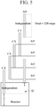
- FIG. 5 is a diagram illustrating movement of the control rods illustrated in FIG. 1 .
- the plurality of load-following control rods CY, CX, and C1 are inserted into the reactor core body RC in the axial direction for the reactivity control corresponding to the output set for the load following operation.
- the first load-following control rod CY, the second load-following control rod CX, and the third load-following control rod C1 included in the plurality of load-following control rods CY, CX, and C1 are sequentially overlapped by 50% (0.5) in the axial direction.
- the first load-following control rod CY, the second load-following control rod CX, and the third load-following control rod C1 is raised and lowered while being automatically inserted into the reactor core body RC in response to the set output.
- first load-following control rod CY, the second load-following control rod CX, and the third load-following control rod C1 may be sequentially overlapped in the axial direction by 30% to 70%.
- the first power axial offset control rod CZ has an end portion positioned below the center of the reactor core body RC in the axial direction for the power axial offset control during the load following operation, and is lowered and raised only below the center of the reactor core body RC in the direction to compensate for the fluctuation in the power axial offset due to the insertion of the plurality of load-following control rods CY, CX, and C1.
- the second power axial offset control rod AO has an end portion positioned on the top of the reactor core body RC in the axial direction for the power axial offset control during the load following operation, and is raised and lowered only on the top of the reactor core body RC to assist the first power axial offset control rod CZ.
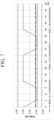
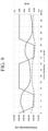
- FIG. 6 is a graph showing control rods critical heights of the control rods during a load following operation at an end of cycle (EOC) of a reactor core for load following operation according to an embodiment.
- EOC end of cycle
- the set output (solid gray line) of the load following operation scenario of the reactor core for load following operation decreases from 100% to 50% over 3 hours at the end of cycle (EOC) of the reactor core body and lasts for 6 hours, and then again increases from 50% to 100% over 3 hours, in which one set lasting for 12 hours is set as two consecutive sets.
- the first load-following control rod CY, the second load-following control rod CX, and the third load-following control rod C1 are inserted into the reactor core body while being sequentially overlapped by 50% in the axial direction in response to the output (solid gray line) set for the load following operation, and thus, a total of 228 steps of the reactor core body are raised and lowered.
- the first power axial offset control rod CZ has an end portion positioned below the center of the reactor core body in the axial direction during the load following operation, and is lowered and raised only below the center (114 steps) of the reactor core body in the direction (i.e., direction in which the first power axial offset control rod CZ is raised when the top is over-output and is lowered when the bottom is over-output) to compensate for the fluctuation in the power axial offset due to the insertion of the first load-following control rod CY, the second load-following control rod CX, and the third load-following control rod C1.
- the first power axial offset control rod CZ is raised and lowered only below the center of the reactor core body in response to the fluctuation in the power axial offset fluctuation while being inserted into the reactor core body by 65% to 75% in the axial direction during the load following operation.
- the second power axial offset control rod AO has the end portion positioned on the top of the reactor core body in the axial direction during the load following operation, and is raised and lowered only the top (top of 171 steps) of the reactor core body in the direction to assist the first power axial offset control rod CZ.
- the first power axial offset control rod CZ is inserted up to 57 steps out of the total of 228 steps.
- boric acid dilution may be performed to compensate for the reactivity. Since the output is biased toward the bottom due to the insertion of the first load-following control rod CY, to prevent this, the first power axial offset control rod CZ is lowered and then the trend of the output distribution starts to reverse, so the first power axial offset control rod CZ is raised.
- the output reaches 50% which is the target level
- the second power axial offset control rod AO is partially inserted, and the second load-following control rod CX and the third load-following control rod C1 are slightly drawn out.
- the compensation for the reactivity varying due to the xenon fluctuation may be finely controlled by moving the second power axial offset control rod AO.
- the power axial offset of the reactor core body is controlled by raising and lowering the first power axial offset control rod CZ, and the varying reactivity is compensated by raising and lowering the second power axial offset control rod AO.
- the second power axial offset control rod AO is completely drawn out from the reactor core body, and the second load-following control rod CX and the third load-following control rod C1 are slightly inserted. After recovering 100% output, the power axial offset is adjusted using the first power axial offset control rod CZ.
- the fluctuation in the power axial offset (Power AO) during the load following operation corresponding to the output set for the load following operation is 0.02 at most.
- FIG. 9 is a graph illustrating the xenon axial offset during the load following operation of the reactor core for load following operation according to an embodiment.
- the X axis represents time
- the left Y axis represents xenon density (Xe density)
- the right Y axis represents a xenon axial offset (Xe AO).
- a reactor core for load following operation capable of minimizing fluctuations in power axial offset and xenon axial offset during a load following operation of a nuclear power plant.
- RC Reactor core body
- CY, CX, C1 Load-following control rod
- CZ First power axial offset control rod
- AO Second power axial offset control rod
Landscapes
- Physics & Mathematics (AREA)
- Engineering & Computer Science (AREA)
- Plasma & Fusion (AREA)
- General Engineering & Computer Science (AREA)
- High Energy & Nuclear Physics (AREA)
- Chemical & Material Sciences (AREA)
- Chemical Kinetics & Catalysis (AREA)
- Monitoring And Testing Of Nuclear Reactors (AREA)
Claims (9)
- Noyau de réacteur pour opération avec suivi de charge, comprenant :un corps de noyau de réacteur (RC) ;une pluralité de tiges de commande de suivi de charge (CY, CX, C1) qui sont configurées pour être insérées dans le corps de noyau de réacteur (RC) dans une direction axiale en réponse à un ensemble de sortie pour l'opération de suivi de charge, se chevauchent dans la direction axiale, et sont configurées pour être simultanément levées et abaissées, caractérisé en ce que le noyau de réacteur comprend en outreune première tige de commande de décalage axial de puissance (CZ) qui est espacée de la pluralité de tiges de commande de suivi de charge (CY, CX, C1) dans un plan, a une partie d'extrémité positionnée sous un centre du corps de noyau de réacteur (RC) dans la direction axiale, et est configurée pour être levée et abaissée uniquement sous le centre du corps de noyau de réacteur (RC) dans une direction pour compenser une fluctuation d'un décalage axial de puissance en raison de l'insertion de la pluralité de tiges de commande de suivi de charge (CY, CX, C1).
- Noyau de réacteur selon la revendication 1, dans lequel :
la première tige de commande de décalage axial de puissance (CZ) comporte :un matériau absorbant supérieur ayant un premier diamètre ;un matériau absorbant inférieur qui est positionné sous le matériau absorbant supérieur et a un second diamètre plus grand que le premier diamètre ; etun matériau de revêtement qui entoure le matériau absorbant supérieur et le matériau absorbant inférieur, etune épaisseur supérieure du matériau de revêtement entourant le matériau absorbant supérieur est plus épaisse qu'une épaisseur inférieure du matériau de revêtement entourant le matériau absorbant inférieur. - Noyau de réacteur selon la revendication 2, dans lequel :
le matériau absorbant supérieur et le matériau absorbant inférieur contiennent un alliage Ag-In-Cd. - Noyau de réacteur selon la revendication 2, dans lequel :
la pluralité de tiges de commande de suivi de charge (CY, CX, C1) comporte une première tige de commande de suivi de charge (CY), une deuxième tige de commande de suivi de charge (CX) et une troisième tige de commande de suivi de charge (C1) se chevauchant séquentiellement de 30 % à 70 % dans la direction axiale. - Noyau de réacteur selon la revendication 4, dans lequel :la première tige de commande de suivi de charge (CY) et la deuxième tige de commande de suivi de charge (CX) ont la même structure que la première tige de commande de décalage axial de puissance (CZ), etla troisième tige de commande de suivi de charge (C1) a une structure différente de celle de la première tige de commande de décalage axial de puissance (CZ).
- Noyau de réacteur selon la revendication 1, comprenant en outre :
une seconde tige de commande de décalage axial de puissance (AO) qui est espacée de la première tige de commande de décalage axial de puissance (CZ), a une partie d'extrémité positionnée au sommet du corps de noyau de réacteur (RC) dans la direction axiale, et est configurée pour être levée et abaissée uniquement au sommet du corps de noyau de réacteur (RC) dans une direction pour aider la première tige de commande de décalage axial de puissance (CZ). - Noyau de réacteur selon la revendication 6, dans lequel :
la seconde tige de commande de décalage axial de puissance (AO) a une structure différente de celle de la première tige de commande de décalage axial de puissance (CZ). - Noyau de réacteur selon la revendication 1, comprenant en outre :
une pluralité de tiges de commande d'arrêt (SB, SA) qui sont espacées de la pluralité de tiges de commande de suivi de charge (CY, CX, C1) dans un plan, et insérées dans le corps de noyau de réacteur (RC) pour l'arrêt d'un réacteur. - Noyau de réacteur selon la revendication 1, dans lequel :dans le corps de noyau de réacteur (RC), le décalage axial de puissance a une valeur négative pendant une période entière, etle corps de noyau de réacteur (RC) comporte une pluralité de combustibles comportant au moins l'un parmi MOX et UO2.
Applications Claiming Priority (2)
| Application Number | Priority Date | Filing Date | Title |
|---|---|---|---|
| KR1020200071018A KR102463008B1 (ko) | 2020-06-11 | 2020-06-11 | 부하 추종 운전용 노심 |
| PCT/KR2021/007290 WO2021251773A1 (fr) | 2020-06-11 | 2021-06-10 | Noyau pour opération de suivi de charge |
Publications (3)
| Publication Number | Publication Date |
|---|---|
| EP4167251A1 EP4167251A1 (fr) | 2023-04-19 |
| EP4167251A4 EP4167251A4 (fr) | 2024-05-15 |
| EP4167251B1 true EP4167251B1 (fr) | 2025-05-07 |
Family
ID=78845752
Family Applications (1)
| Application Number | Title | Priority Date | Filing Date |
|---|---|---|---|
| EP21821656.2A Active EP4167251B1 (fr) | 2020-06-11 | 2021-06-10 | Noyau pour opération de suivi de charge |
Country Status (4)
| Country | Link |
|---|---|
| EP (1) | EP4167251B1 (fr) |
| KR (1) | KR102463008B1 (fr) |
| CN (1) | CN115917671A (fr) |
| WO (1) | WO2021251773A1 (fr) |
Families Citing this family (4)
| Publication number | Priority date | Publication date | Assignee | Title |
|---|---|---|---|---|
| KR102696301B1 (ko) * | 2022-02-04 | 2024-08-20 | 한국수력원자력 주식회사 | 복수의 소형모듈형 원자로를 포함하는 원자력발전소의 운전방법 |
| CN117012410A (zh) * | 2022-04-29 | 2023-11-07 | 中广核研究院有限公司 | 压水堆堆芯控制方法、装置、计算机设备、存储介质 |
| JP2024063575A (ja) * | 2022-10-26 | 2024-05-13 | 日立Geニュークリア・エナジー株式会社 | 炉心の制御方法 |
| KR102900926B1 (ko) * | 2023-03-20 | 2025-12-15 | 한국수력원자력 주식회사 | 원자로 부하 추종 운전 시스템 |
Family Cites Families (7)
| Publication number | Priority date | Publication date | Assignee | Title |
|---|---|---|---|---|
| JPS58105088A (ja) * | 1981-12-18 | 1983-06-22 | 株式会社東芝 | 原子炉の制御棒 |
| KR100443369B1 (ko) * | 2001-11-23 | 2004-08-09 | 한국과학기술원 | 가압경수로형 원자로용 하부 치우침 강도 제어봉 |
| KR100595820B1 (ko) * | 2003-05-16 | 2006-07-03 | 한국과학기술원 | 가압경수로형 원자로용 축 방향 다분할 강도 제어봉 |
| US8532246B2 (en) * | 2007-08-17 | 2013-09-10 | Westinghouse Electric Company Llc | Nuclear reactor robust gray control rod |
| WO2011143172A1 (fr) * | 2010-05-11 | 2011-11-17 | Thorium Power, Inc. | Assemblage de combustible à noyau d'alliage de combustibles métalliques et son procédé de fabrication |
| KR101668088B1 (ko) * | 2015-05-13 | 2016-10-19 | 한국원자력연구원 | 원자로 |
| RU2691628C1 (ru) * | 2018-09-03 | 2019-06-17 | Акционерное общество "Высокотехнологический научно-исследовательский институт неорганических материалов имени академика А.А. Бочвара" | Твэл ядерного реактора |
-
2020
- 2020-06-11 KR KR1020200071018A patent/KR102463008B1/ko active Active
-
2021
- 2021-06-10 WO PCT/KR2021/007290 patent/WO2021251773A1/fr not_active Ceased
- 2021-06-10 EP EP21821656.2A patent/EP4167251B1/fr active Active
- 2021-06-10 CN CN202180042029.4A patent/CN115917671A/zh active Pending
Also Published As
| Publication number | Publication date |
|---|---|
| EP4167251A1 (fr) | 2023-04-19 |
| EP4167251A4 (fr) | 2024-05-15 |
| WO2021251773A1 (fr) | 2021-12-16 |
| CN115917671A (zh) | 2023-04-04 |
| KR20210153982A (ko) | 2021-12-20 |
| KR102463008B1 (ko) | 2022-11-02 |
Similar Documents
| Publication | Publication Date | Title |
|---|---|---|
| EP4167251B1 (fr) | Noyau pour opération de suivi de charge | |
| Karoutas et al. | The maturing of nuclear fuel: Past to Accident Tolerant Fuel | |
| JPH0445795B2 (fr) | ||
| Onoue et al. | Application of MSHIM core control strategy for Westinghouse AP1000 nuclear power plant | |
| Franceschini et al. | Advanced operational strategy for the IRIS reactor: Load follow through mechanical shim (MSHIM) | |
| EP0124775A1 (fr) | Assemblage combustible | |
| Raj et al. | Operational characteristics of LWR core fuelled with thorium-based fuel | |
| JPH067194B2 (ja) | 軽水型原子炉炉心およびその燃料装荷方法 | |
| Chaudri et al. | Excess reactivity control using innovative burnable absorber configuration for a 24-month cycle APR-1400 | |
| Franceschini et al. | Core physics analysis of 100% MOX core in IRIS | |
| Cho et al. | The Analysis of the MTC Effect for Controlling Secondary Reactivity Based on Coolant Temperature for Soluble Boron-free SMR Core | |
| JP5085522B2 (ja) | 長期連続運転用原子炉の炉心 | |
| Leer et al. | Fast modular reactor nuclear design parameters of fuel cycle and power distributions | |
| JP3943624B2 (ja) | 燃料集合体 | |
| JP2610254B2 (ja) | 沸騰水型原子炉 | |
| Akie et al. | Core burnup calculation and accidents analyses of a pressurized water reactor partially loaded with rock-like oxide fuel | |
| JP3318193B2 (ja) | 燃料装荷方法 | |
| JP2966877B2 (ja) | 燃料集合体 | |
| JPS63127190A (ja) | 原子炉燃料集合体 | |
| Bi et al. | Control Strategy of Soluble Boron-Free Operation for a Small PWR | |
| JP3130602B2 (ja) | 原子炉の炉心および燃料集合体群 | |
| JP3117207B2 (ja) | 沸騰水型原子炉用燃料集合体 | |
| JP3085715B2 (ja) | 原子炉の運転方法 | |
| Cudrnak et al. | Optimization of fuel assembly with gadolinium for LWRS | |
| JP3441149B2 (ja) | 原子炉の炉心 |
Legal Events
| Date | Code | Title | Description |
|---|---|---|---|
| STAA | Information on the status of an ep patent application or granted ep patent |
Free format text: STATUS: THE INTERNATIONAL PUBLICATION HAS BEEN MADE |
|
| PUAI | Public reference made under article 153(3) epc to a published international application that has entered the european phase |
Free format text: ORIGINAL CODE: 0009012 |
|
| STAA | Information on the status of an ep patent application or granted ep patent |
Free format text: STATUS: REQUEST FOR EXAMINATION WAS MADE |
|
| 17P | Request for examination filed |
Effective date: 20221122 |
|
| AK | Designated contracting states |
Kind code of ref document: A1 Designated state(s): AL AT BE BG CH CY CZ DE DK EE ES FI FR GB GR HR HU IE IS IT LI LT LU LV MC MK MT NL NO PL PT RO RS SE SI SK SM TR |
|
| DAV | Request for validation of the european patent (deleted) | ||
| DAX | Request for extension of the european patent (deleted) | ||
| REG | Reference to a national code |
Ref country code: DE Free format text: PREVIOUS MAIN CLASS: G21C0007080000 Ref country code: DE Ref legal event code: R079 Ref document number: 602021030555 Country of ref document: DE Free format text: PREVIOUS MAIN CLASS: G21C0007080000 Ipc: G21C0007100000 |
|
| A4 | Supplementary search report drawn up and despatched |
Effective date: 20240416 |
|
| RIC1 | Information provided on ipc code assigned before grant |
Ipc: G21D 3/08 20060101ALI20240411BHEP Ipc: G21C 7/08 20060101ALI20240411BHEP Ipc: G21D 3/16 20060101ALI20240411BHEP Ipc: G21C 7/10 20060101AFI20240411BHEP |
|
| GRAP | Despatch of communication of intention to grant a patent |
Free format text: ORIGINAL CODE: EPIDOSNIGR1 |
|
| STAA | Information on the status of an ep patent application or granted ep patent |
Free format text: STATUS: GRANT OF PATENT IS INTENDED |
|
| INTG | Intention to grant announced |
Effective date: 20241213 |
|
| GRAS | Grant fee paid |
Free format text: ORIGINAL CODE: EPIDOSNIGR3 |
|
| GRAA | (expected) grant |
Free format text: ORIGINAL CODE: 0009210 |
|
| STAA | Information on the status of an ep patent application or granted ep patent |
Free format text: STATUS: THE PATENT HAS BEEN GRANTED |
|
| AK | Designated contracting states |
Kind code of ref document: B1 Designated state(s): AL AT BE BG CH CY CZ DE DK EE ES FI FR GB GR HR HU IE IS IT LI LT LU LV MC MK MT NL NO PL PT RO RS SE SI SK SM TR |
|
| REG | Reference to a national code |
Ref country code: GB Ref legal event code: FG4D |
|
| REG | Reference to a national code |
Ref country code: CH Ref legal event code: EP |
|
| REG | Reference to a national code |
Ref country code: DE Ref legal event code: R096 Ref document number: 602021030555 Country of ref document: DE |
|
| REG | Reference to a national code |
Ref country code: IE Ref legal event code: FG4D |
|
| PGFP | Annual fee paid to national office [announced via postgrant information from national office to epo] |
Ref country code: AT Payment date: 20250721 Year of fee payment: 5 |
|
| REG | Reference to a national code |
Ref country code: NL Ref legal event code: MP Effective date: 20250507 |
|
| PG25 | Lapsed in a contracting state [announced via postgrant information from national office to epo] |
Ref country code: PT Free format text: LAPSE BECAUSE OF FAILURE TO SUBMIT A TRANSLATION OF THE DESCRIPTION OR TO PAY THE FEE WITHIN THE PRESCRIBED TIME-LIMIT Effective date: 20250908 Ref country code: FI Free format text: LAPSE BECAUSE OF FAILURE TO SUBMIT A TRANSLATION OF THE DESCRIPTION OR TO PAY THE FEE WITHIN THE PRESCRIBED TIME-LIMIT Effective date: 20250507 Ref country code: ES Free format text: LAPSE BECAUSE OF FAILURE TO SUBMIT A TRANSLATION OF THE DESCRIPTION OR TO PAY THE FEE WITHIN THE PRESCRIBED TIME-LIMIT Effective date: 20250507 |
|
| PGFP | Annual fee paid to national office [announced via postgrant information from national office to epo] |
Ref country code: DE Payment date: 20250702 Year of fee payment: 5 |
|
| REG | Reference to a national code |
Ref country code: LT Ref legal event code: MG9D |
|
| PG25 | Lapsed in a contracting state [announced via postgrant information from national office to epo] |
Ref country code: NO Free format text: LAPSE BECAUSE OF FAILURE TO SUBMIT A TRANSLATION OF THE DESCRIPTION OR TO PAY THE FEE WITHIN THE PRESCRIBED TIME-LIMIT Effective date: 20250807 Ref country code: GR Free format text: LAPSE BECAUSE OF FAILURE TO SUBMIT A TRANSLATION OF THE DESCRIPTION OR TO PAY THE FEE WITHIN THE PRESCRIBED TIME-LIMIT Effective date: 20250808 |
|
| PG25 | Lapsed in a contracting state [announced via postgrant information from national office to epo] |
Ref country code: NL Free format text: LAPSE BECAUSE OF FAILURE TO SUBMIT A TRANSLATION OF THE DESCRIPTION OR TO PAY THE FEE WITHIN THE PRESCRIBED TIME-LIMIT Effective date: 20250507 Ref country code: PL Free format text: LAPSE BECAUSE OF FAILURE TO SUBMIT A TRANSLATION OF THE DESCRIPTION OR TO PAY THE FEE WITHIN THE PRESCRIBED TIME-LIMIT Effective date: 20250507 |
|
| REG | Reference to a national code |
Ref country code: AT Ref legal event code: MK05 Ref document number: 1793426 Country of ref document: AT Kind code of ref document: T Effective date: 20250507 |
|
| PG25 | Lapsed in a contracting state [announced via postgrant information from national office to epo] |
Ref country code: BG Free format text: LAPSE BECAUSE OF FAILURE TO SUBMIT A TRANSLATION OF THE DESCRIPTION OR TO PAY THE FEE WITHIN THE PRESCRIBED TIME-LIMIT Effective date: 20250507 |
|
| PG25 | Lapsed in a contracting state [announced via postgrant information from national office to epo] |
Ref country code: HR Free format text: LAPSE BECAUSE OF FAILURE TO SUBMIT A TRANSLATION OF THE DESCRIPTION OR TO PAY THE FEE WITHIN THE PRESCRIBED TIME-LIMIT Effective date: 20250507 |
|
| PG25 | Lapsed in a contracting state [announced via postgrant information from national office to epo] |
Ref country code: AT Free format text: LAPSE BECAUSE OF FAILURE TO SUBMIT A TRANSLATION OF THE DESCRIPTION OR TO PAY THE FEE WITHIN THE PRESCRIBED TIME-LIMIT Effective date: 20250507 |
|
| PG25 | Lapsed in a contracting state [announced via postgrant information from national office to epo] |
Ref country code: RS Free format text: LAPSE BECAUSE OF FAILURE TO SUBMIT A TRANSLATION OF THE DESCRIPTION OR TO PAY THE FEE WITHIN THE PRESCRIBED TIME-LIMIT Effective date: 20250807 |
|
| PG25 | Lapsed in a contracting state [announced via postgrant information from national office to epo] |
Ref country code: IS Free format text: LAPSE BECAUSE OF FAILURE TO SUBMIT A TRANSLATION OF THE DESCRIPTION OR TO PAY THE FEE WITHIN THE PRESCRIBED TIME-LIMIT Effective date: 20250907 |
|
| PG25 | Lapsed in a contracting state [announced via postgrant information from national office to epo] |
Ref country code: LV Free format text: LAPSE BECAUSE OF FAILURE TO SUBMIT A TRANSLATION OF THE DESCRIPTION OR TO PAY THE FEE WITHIN THE PRESCRIBED TIME-LIMIT Effective date: 20250507 |
|
| PG25 | Lapsed in a contracting state [announced via postgrant information from national office to epo] |
Ref country code: SM Free format text: LAPSE BECAUSE OF FAILURE TO SUBMIT A TRANSLATION OF THE DESCRIPTION OR TO PAY THE FEE WITHIN THE PRESCRIBED TIME-LIMIT Effective date: 20250507 Ref country code: DK Free format text: LAPSE BECAUSE OF FAILURE TO SUBMIT A TRANSLATION OF THE DESCRIPTION OR TO PAY THE FEE WITHIN THE PRESCRIBED TIME-LIMIT Effective date: 20250507 |
|
| PG25 | Lapsed in a contracting state [announced via postgrant information from national office to epo] |
Ref country code: CZ Free format text: LAPSE BECAUSE OF FAILURE TO SUBMIT A TRANSLATION OF THE DESCRIPTION OR TO PAY THE FEE WITHIN THE PRESCRIBED TIME-LIMIT Effective date: 20250507 |
|
| PG25 | Lapsed in a contracting state [announced via postgrant information from national office to epo] |
Ref country code: EE Free format text: LAPSE BECAUSE OF FAILURE TO SUBMIT A TRANSLATION OF THE DESCRIPTION OR TO PAY THE FEE WITHIN THE PRESCRIBED TIME-LIMIT Effective date: 20250507 |
|
| PG25 | Lapsed in a contracting state [announced via postgrant information from national office to epo] |
Ref country code: SK Free format text: LAPSE BECAUSE OF FAILURE TO SUBMIT A TRANSLATION OF THE DESCRIPTION OR TO PAY THE FEE WITHIN THE PRESCRIBED TIME-LIMIT Effective date: 20250507 |
|
| REG | Reference to a national code |
Ref country code: CH Ref legal event code: H13 Free format text: ST27 STATUS EVENT CODE: U-0-0-H10-H13 (AS PROVIDED BY THE NATIONAL OFFICE) Effective date: 20260127 |
|
| PG25 | Lapsed in a contracting state [announced via postgrant information from national office to epo] |
Ref country code: IT Free format text: LAPSE BECAUSE OF FAILURE TO SUBMIT A TRANSLATION OF THE DESCRIPTION OR TO PAY THE FEE WITHIN THE PRESCRIBED TIME-LIMIT Effective date: 20250507 |
|
| PG25 | Lapsed in a contracting state [announced via postgrant information from national office to epo] |
Ref country code: RO Free format text: LAPSE BECAUSE OF FAILURE TO SUBMIT A TRANSLATION OF THE DESCRIPTION OR TO PAY THE FEE WITHIN THE PRESCRIBED TIME-LIMIT Effective date: 20250507 |
|
| REG | Reference to a national code |
Ref country code: DE Ref legal event code: R097 Ref document number: 602021030555 Country of ref document: DE |
|
| PG25 | Lapsed in a contracting state [announced via postgrant information from national office to epo] |
Ref country code: LU Free format text: LAPSE BECAUSE OF NON-PAYMENT OF DUE FEES Effective date: 20250610 |
|
| PG25 | Lapsed in a contracting state [announced via postgrant information from national office to epo] |
Ref country code: MC Free format text: LAPSE BECAUSE OF FAILURE TO SUBMIT A TRANSLATION OF THE DESCRIPTION OR TO PAY THE FEE WITHIN THE PRESCRIBED TIME-LIMIT Effective date: 20250507 |
|
| REG | Reference to a national code |
Ref country code: BE Ref legal event code: MM Effective date: 20250630 |
|
| PLBE | No opposition filed within time limit |
Free format text: ORIGINAL CODE: 0009261 |
|
| STAA | Information on the status of an ep patent application or granted ep patent |
Free format text: STATUS: NO OPPOSITION FILED WITHIN TIME LIMIT |
|
| REG | Reference to a national code |
Ref country code: CH Ref legal event code: L10 Free format text: ST27 STATUS EVENT CODE: U-0-0-L10-L00 (AS PROVIDED BY THE NATIONAL OFFICE) Effective date: 20260318 |
|
| PG25 | Lapsed in a contracting state [announced via postgrant information from national office to epo] |
Ref country code: IE Free format text: LAPSE BECAUSE OF NON-PAYMENT OF DUE FEES Effective date: 20250610 |
|
| 26N | No opposition filed |
Effective date: 20260210 |
|
| PG25 | Lapsed in a contracting state [announced via postgrant information from national office to epo] |
Ref country code: BE Free format text: LAPSE BECAUSE OF NON-PAYMENT OF DUE FEES Effective date: 20250630 |
|
| PG25 | Lapsed in a contracting state [announced via postgrant information from national office to epo] |
Ref country code: FR Free format text: LAPSE BECAUSE OF NON-PAYMENT OF DUE FEES Effective date: 20250707 |