EP4167329B1 - Porte-batterie pour un véhicule électrique et procédé de fabrication d'un tel porte-batterie - Google Patents
Porte-batterie pour un véhicule électrique et procédé de fabrication d'un tel porte-batterie Download PDFInfo
- Publication number
- EP4167329B1 EP4167329B1 EP21202414.5A EP21202414A EP4167329B1 EP 4167329 B1 EP4167329 B1 EP 4167329B1 EP 21202414 A EP21202414 A EP 21202414A EP 4167329 B1 EP4167329 B1 EP 4167329B1
- Authority
- EP
- European Patent Office
- Prior art keywords
- side wall
- battery carrier
- section
- aluminum material
- sections
- Prior art date
- Legal status (The legal status is an assumption and is not a legal conclusion. Google has not performed a legal analysis and makes no representation as to the accuracy of the status listed.)
- Active
Links
Images


Classifications
-
- B—PERFORMING OPERATIONS; TRANSPORTING
- B60—VEHICLES IN GENERAL
- B60K—ARRANGEMENT OR MOUNTING OF PROPULSION UNITS OR OF TRANSMISSIONS IN VEHICLES; ARRANGEMENT OR MOUNTING OF PLURAL DIVERSE PRIME-MOVERS IN VEHICLES; AUXILIARY DRIVES FOR VEHICLES; INSTRUMENTATION OR DASHBOARDS FOR VEHICLES; ARRANGEMENTS IN CONNECTION WITH COOLING, AIR INTAKE, GAS EXHAUST OR FUEL SUPPLY OF PROPULSION UNITS IN VEHICLES
- B60K1/00—Arrangement or mounting of electrical propulsion units
- B60K1/04—Arrangement or mounting of electrical propulsion units of the electric storage means for propulsion
-
- B—PERFORMING OPERATIONS; TRANSPORTING
- B60—VEHICLES IN GENERAL
- B60L—PROPULSION OF ELECTRICALLY-PROPELLED VEHICLES; SUPPLYING ELECTRIC POWER FOR AUXILIARY EQUIPMENT OF ELECTRICALLY-PROPELLED VEHICLES; ELECTRODYNAMIC BRAKE SYSTEMS FOR VEHICLES IN GENERAL; MAGNETIC SUSPENSION OR LEVITATION FOR VEHICLES; MONITORING OPERATING VARIABLES OF ELECTRICALLY-PROPELLED VEHICLES; ELECTRIC SAFETY DEVICES FOR ELECTRICALLY-PROPELLED VEHICLES
- B60L50/00—Electric propulsion with power supplied within the vehicle
- B60L50/50—Electric propulsion with power supplied within the vehicle using propulsion power supplied by batteries or fuel cells
- B60L50/60—Electric propulsion with power supplied within the vehicle using propulsion power supplied by batteries or fuel cells using power supplied by batteries
- B60L50/66—Arrangements of batteries
-
- H—ELECTRICITY
- H01—ELECTRIC ELEMENTS
- H01M—PROCESSES OR MEANS, e.g. BATTERIES, FOR THE DIRECT CONVERSION OF CHEMICAL ENERGY INTO ELECTRICAL ENERGY
- H01M10/00—Secondary cells; Manufacture thereof
- H01M10/04—Construction or manufacture in general
- H01M10/0413—Large-sized flat cells or batteries for motive or stationary systems with plate-like electrodes
-
- H—ELECTRICITY
- H01—ELECTRIC ELEMENTS
- H01M—PROCESSES OR MEANS, e.g. BATTERIES, FOR THE DIRECT CONVERSION OF CHEMICAL ENERGY INTO ELECTRICAL ENERGY
- H01M50/00—Constructional details or processes of manufacture of the non-active parts of electrochemical cells other than fuel cells, e.g. hybrid cells
- H01M50/20—Mountings; Secondary casings or frames; Racks, modules or packs; Suspension devices; Shock absorbers; Transport or carrying devices; Holders
- H01M50/218—Mountings; Secondary casings or frames; Racks, modules or packs; Suspension devices; Shock absorbers; Transport or carrying devices; Holders characterised by the material
- H01M50/22—Mountings; Secondary casings or frames; Racks, modules or packs; Suspension devices; Shock absorbers; Transport or carrying devices; Holders characterised by the material of the casings or racks
- H01M50/222—Inorganic material
- H01M50/224—Metals
-
- H—ELECTRICITY
- H01—ELECTRIC ELEMENTS
- H01M—PROCESSES OR MEANS, e.g. BATTERIES, FOR THE DIRECT CONVERSION OF CHEMICAL ENERGY INTO ELECTRICAL ENERGY
- H01M50/00—Constructional details or processes of manufacture of the non-active parts of electrochemical cells other than fuel cells, e.g. hybrid cells
- H01M50/20—Mountings; Secondary casings or frames; Racks, modules or packs; Suspension devices; Shock absorbers; Transport or carrying devices; Holders
- H01M50/233—Mountings; Secondary casings or frames; Racks, modules or packs; Suspension devices; Shock absorbers; Transport or carrying devices; Holders characterised by physical properties of casings or racks, e.g. dimensions
- H01M50/236—Hardness
-
- H—ELECTRICITY
- H01—ELECTRIC ELEMENTS
- H01M—PROCESSES OR MEANS, e.g. BATTERIES, FOR THE DIRECT CONVERSION OF CHEMICAL ENERGY INTO ELECTRICAL ENERGY
- H01M50/00—Constructional details or processes of manufacture of the non-active parts of electrochemical cells other than fuel cells, e.g. hybrid cells
- H01M50/20—Mountings; Secondary casings or frames; Racks, modules or packs; Suspension devices; Shock absorbers; Transport or carrying devices; Holders
- H01M50/233—Mountings; Secondary casings or frames; Racks, modules or packs; Suspension devices; Shock absorbers; Transport or carrying devices; Holders characterised by physical properties of casings or racks, e.g. dimensions
- H01M50/238—Flexibility or foldability
-
- H—ELECTRICITY
- H01—ELECTRIC ELEMENTS
- H01M—PROCESSES OR MEANS, e.g. BATTERIES, FOR THE DIRECT CONVERSION OF CHEMICAL ENERGY INTO ELECTRICAL ENERGY
- H01M50/00—Constructional details or processes of manufacture of the non-active parts of electrochemical cells other than fuel cells, e.g. hybrid cells
- H01M50/20—Mountings; Secondary casings or frames; Racks, modules or packs; Suspension devices; Shock absorbers; Transport or carrying devices; Holders
- H01M50/233—Mountings; Secondary casings or frames; Racks, modules or packs; Suspension devices; Shock absorbers; Transport or carrying devices; Holders characterised by physical properties of casings or racks, e.g. dimensions
- H01M50/242—Mountings; Secondary casings or frames; Racks, modules or packs; Suspension devices; Shock absorbers; Transport or carrying devices; Holders characterised by physical properties of casings or racks, e.g. dimensions adapted for protecting batteries against vibrations, collision impact or swelling
-
- H—ELECTRICITY
- H01—ELECTRIC ELEMENTS
- H01M—PROCESSES OR MEANS, e.g. BATTERIES, FOR THE DIRECT CONVERSION OF CHEMICAL ENERGY INTO ELECTRICAL ENERGY
- H01M50/00—Constructional details or processes of manufacture of the non-active parts of electrochemical cells other than fuel cells, e.g. hybrid cells
- H01M50/20—Mountings; Secondary casings or frames; Racks, modules or packs; Suspension devices; Shock absorbers; Transport or carrying devices; Holders
- H01M50/247—Mountings; Secondary casings or frames; Racks, modules or packs; Suspension devices; Shock absorbers; Transport or carrying devices; Holders specially adapted for portable devices, e.g. mobile phones, computers, hand tools or pacemakers
-
- H—ELECTRICITY
- H01—ELECTRIC ELEMENTS
- H01M—PROCESSES OR MEANS, e.g. BATTERIES, FOR THE DIRECT CONVERSION OF CHEMICAL ENERGY INTO ELECTRICAL ENERGY
- H01M50/00—Constructional details or processes of manufacture of the non-active parts of electrochemical cells other than fuel cells, e.g. hybrid cells
- H01M50/20—Mountings; Secondary casings or frames; Racks, modules or packs; Suspension devices; Shock absorbers; Transport or carrying devices; Holders
- H01M50/249—Mountings; Secondary casings or frames; Racks, modules or packs; Suspension devices; Shock absorbers; Transport or carrying devices; Holders specially adapted for aircraft or vehicles, e.g. cars or trains
-
- B—PERFORMING OPERATIONS; TRANSPORTING
- B60—VEHICLES IN GENERAL
- B60K—ARRANGEMENT OR MOUNTING OF PROPULSION UNITS OR OF TRANSMISSIONS IN VEHICLES; ARRANGEMENT OR MOUNTING OF PLURAL DIVERSE PRIME-MOVERS IN VEHICLES; AUXILIARY DRIVES FOR VEHICLES; INSTRUMENTATION OR DASHBOARDS FOR VEHICLES; ARRANGEMENTS IN CONNECTION WITH COOLING, AIR INTAKE, GAS EXHAUST OR FUEL SUPPLY OF PROPULSION UNITS IN VEHICLES
- B60K1/00—Arrangement or mounting of electrical propulsion units
- B60K1/04—Arrangement or mounting of electrical propulsion units of the electric storage means for propulsion
- B60K2001/0405—Arrangement or mounting of electrical propulsion units of the electric storage means for propulsion characterised by their position
- B60K2001/0438—Arrangement under the floor
-
- H—ELECTRICITY
- H01—ELECTRIC ELEMENTS
- H01M—PROCESSES OR MEANS, e.g. BATTERIES, FOR THE DIRECT CONVERSION OF CHEMICAL ENERGY INTO ELECTRICAL ENERGY
- H01M2220/00—Batteries for particular applications
- H01M2220/20—Batteries in motive systems, e.g. vehicle, ship, plane
-
- Y—GENERAL TAGGING OF NEW TECHNOLOGICAL DEVELOPMENTS; GENERAL TAGGING OF CROSS-SECTIONAL TECHNOLOGIES SPANNING OVER SEVERAL SECTIONS OF THE IPC; TECHNICAL SUBJECTS COVERED BY FORMER USPC CROSS-REFERENCE ART COLLECTIONS [XRACs] AND DIGESTS
- Y02—TECHNOLOGIES OR APPLICATIONS FOR MITIGATION OR ADAPTATION AGAINST CLIMATE CHANGE
- Y02E—REDUCTION OF GREENHOUSE GAS [GHG] EMISSIONS, RELATED TO ENERGY GENERATION, TRANSMISSION OR DISTRIBUTION
- Y02E60/00—Enabling technologies; Technologies with a potential or indirect contribution to GHG emissions mitigation
- Y02E60/10—Energy storage using batteries
Definitions
- the invention relates to a battery carrier which is intended for fastening in a floor area of a supporting structure of an electrically driven motor vehicle, wherein the battery carrier, with a floor section and a side wall section running around the floor section, defines a receiving space for battery elements to be positioned there.
- the invention also relates to a method for producing such a battery carrier.
- Battery carriers of the type in question here also known in technical terms as “battery trays”, contain the storage units in which the electrical energy required to drive the motor vehicle is stored. These usually rechargeable energy storage units are referred to synonymously as “batteries” or “accumulators” in common parlance. For the sake of simplicity, the term “battery” is therefore used throughout this text to refer to the energy storage units in question. Batteries of this type are usually made up of several cell-like battery elements.
- Lithium-ion batteries are state of the art and enable high energy density while also having a comparatively long service life.
- Li-ion batteries are sensitive to mechanical and thermal stress. Damage to the battery elements can lead to fires and the release of toxic components. These toxic components can pose a significant risk if they are released into the environment in an uncontrolled manner. For example, if the highly reactive lithium metal of a Li-ion battery comes into contact with water, the water molecules are broken down into their components hydrogen and oxygen, which form a gas mixture that is highly explosive.
- battery carriers of the type in question here must be designed in such a way that the battery elements arranged in them can not only be protected against mechanical damage during normal driving and in the event of an accident, but also reliably prevent contents of the battery elements from escaping into the environment in the event of a leak.
- the supporting structure for an electrically powered vehicle presented there comprises a base part which has a rectangular frame designed like a ladder and extending in the longitudinal direction of the supporting structure.
- the frame has compartments in each of which a plate-shaped battery can be inserted.
- the frame On its narrow sides, the frame has a coupling section via which the battery housing is connected to other components of the supporting structure, such as profiles for coupling to the axle units or the outer skin of the vehicle.
- the frame is attached to Its underside is covered with a plate. There is also a cover on the frame to protect the vehicle's occupants from fumes or similar escaping from the batteries in the event of a battery failure.
- This battery carrier which has the generic features of the invention, delimits a receiving space in the manner of a trough with its base and a side wall running around the base, in which the battery elements are arranged for use. At least one segment of the trough, preferably the entire trough, is made as a folding component in one piece and from a single material from a circuit board.
- a flat, suitably shaped sheet metal blank is provided, in which in the area of the beads to be created, cutouts are cut into the sections that later form the side wall sections of the battery carrier.
- the battery carrier is formed from the blank prepared in this way by various folding operations along predetermined edge lines so that the beads are formed in the base and the side wall sections protrude vertically from the base.
- the joints at which two side wall sections or one side wall section and one end of one of the beads meet are then joined together, with the connection between the joined parts preferably being carried out as a material-bonded connection, in particular as a weld.
- a battery pack comprising a punching basin is known, wherein the punching basin forms a receiving space and wherein the receiving space is divided into a plurality of sub-receiving spaces by steel rod supports.
- the DE 10 2017 120 533 A1 relates to a battery carrier for an electric vehicle having a tray for accommodating batteries and optionally a lid for closing the tray, wherein the tray is designed as a sheet metal component with at least two opposite side walls, which are made in one piece and of the same material from a sheet metal plate with the base.
- JP 2021-68523 A discloses a battery housing unit comprising a container body, a lid and at least one inner reinforcing material.
- the container body is formed from a deep-drawn product of a 5000 series aluminum alloy and has a bottom wall and a peripheral wall integrally connected to the bottom wall.
- the lid is mounted on the container body to cover the interior of the container at a position above the container body.
- the inner reinforcing material is made of a 7000 series aluminum alloy.
- the DE 10 2017 102 685 A1 relates to a tray for a battery carrier for arrangement on an electric motor vehicle, wherein the battery carrier is suitable for receiving at least one battery and the tray is produced as a sheet metal component deep-drawn from an aluminum alloy with a base and walls arranged at an angle ⁇ to the base.
- a method for producing such a battery carrier should also be specified.
- the invention has solved this problem by a battery carrier which has at least the features specified in claim 1.
- the invention has also solved this problem by the method specified in claim 8.
- a battery carrier according to the invention which is intended for fastening in a floor area of a support structure of an electrically powered motor vehicle, thus delimits a receiving space for at least one battery element to be positioned there with a floor section and a side wall running around the floor section.
- the side wall comprises at least two side wall sections which are angled at an angle of more than 0° to the floor section and meet in a corner area.
- the bottom section of the battery carrier is formed in one piece from a first aluminum material.
- side wall sections, including the The respective corner area is formed in one piece from a second aluminium material which has a higher elongation at break A than the first aluminium material.
- the first aluminum material used according to the invention for the base section has a tensile strength Rm of at least 170 MPa (Rm ⁇ 170 MPa), for example at least 220 MPa (Rm ⁇ 220 MPa), in particular at least 240 MPa (Rm ⁇ 240 MPa), and an elongation at break A of up to 10% (A ⁇ 10%), in particular up to 8% (A ⁇ 8%).
- Rm ⁇ 170 MPa for example at least 220 MPa (Rm ⁇ 220 MPa), in particular at least 240 MPa (Rm ⁇ 240 MPa)
- an elongation at break A of up to 10% (A ⁇ 10%), in particular up to 8% (A ⁇ 8%).
- Aluminum materials with such a range of properties are referred to in the specialist world, as well as in the present text, as "high-strength aluminum materials.”
- the elongation at break A of the second aluminum material, from which the side wall sections that meet in a corner area and the corner area in question are formed in one piece is typically at least 10% (A ⁇ 10), in particular at least 15% (A ⁇ 15%).
- Aluminum materials with such a high elongation at break A are referred to in technical terms, as in this text, as "ductile aluminum materials.”
- the base section of a battery carrier according to the invention thus consists of a high-strength aluminum material, while at least the side wall sections meeting in a corner region and the relevant corner region formed in one piece with them consist of a ductile aluminum material.
- a battery carrier according to the invention is therefore characterized by the fact that it is made entirely of aluminum materials. This gives it a significantly lower weight than conventional sheet steel constructions.
- the invention is based on the idea of using an aluminum material for the base section, which is exposed to the greatest stresses from stone chips and the like during use and also has to bear the weight of the battery elements.
- This material has a high level of strength and as such can safely withstand the mechanical stresses acting on it.
- additional molded elements with complex shapes or which are difficult to produce using forming technology are placed in the area of those side wall sections of the battery carrier which are made of an aluminum material with increased elongation properties compared to the material of the base section and therefore optimized deformability. In this way, it is possible to form the battery carrier according to the invention by forming in one piece from a suitably shaped sheet metal blank, despite the fact that the base section made of high-strength aluminum material is insufficiently deformable for complex shaping.
- a sheet metal plate can be used to produce a battery carrier according to the invention, the sections of which are made of different aluminum materials and are connected to one another using proven joining techniques, in particular welding or gluing techniques, in such a way that a firm and tight cohesion of these sections is ensured even after the plate has been formed into the battery carrier.
- the invention uses the proven principle of tailor-welded blanks, which is based on the use of tailored-welded blanks. Manufacturing of components that have different local requirements (see for example DE 10 2011 101 586 B4 ).
- the invention not only succeeds in providing a battery carrier of low weight that reliably meets the requirements placed on its load-bearing capacity.
- the tightness of the connection between the individual sections is always guaranteed in a battery carrier according to the invention. This is achieved not least by the fact that the corner areas of the battery carrier, which are particularly critical with regard to shape and cracking, are located exclusively in the side wall sections, which are made of ductile, easily deformable aluminum material. In this way, despite the deformations that inevitably occur during use and the associated stresses in the battery carrier, a permanently tight shielding of the battery elements arranged in the battery carrier from the environment is guaranteed.
- the central base section of a battery carrier according to the invention consisting of the higher-strength aluminum material, is, for example, essentially flat, so that it is deformed at most with a small degree of deformation when the battery carrier is shaped.
- the base section can of course be provided with beads and similar shaped elements if necessary, which can be reproduced despite the limited deformability of the higher-strength material from which the base section is made.
- Such shaped elements can, for example, improve the dimensional stability of the base section or facilitate the fastening and alignment of the battery elements to be arranged in the battery carrier.
- the central section of the sheet metal plate can also be designed in such a way that it not only forms the base section of a battery carrier according to the invention, but also at least one section of the side wall, which should, for example, have a particularly high level of strength. This is particularly useful if the wall section in question is simply shaped, i.e., for example, it only has straight, parallel side walls or edges. These should ideally merge into the adjacent side wall section or the base section with such large bending radii that cracking is reliably avoided.
- the geometries suitable for this can be determined in a known manner depending on the strength and elongation properties of the aluminum material used for the base section.
- the battery carrier has a higher-strength side wall section on two opposite sides, which is formed in one piece with the base section from the higher-strength aluminum material of the base section, wherein one of the ductile side wall sections, which have a corner region of the battery carrier between them, forms an extension of the respective higher-strength side wall section, which can extend in particular along the base section.
- the base section of a battery carrier according to the invention can, for example, have a rectangular basic shape in which a higher-strength side wall section extends on opposite longitudinal sides of the base section, wherein the higher-strength side sections are each extended on their sides assigned to the corner regions of the battery carrier by a ductile side wall section joined to them, in particular welded.
- the corner areas which are critical with regard to the forming behavior, in particular the risk of cracking, are relocated in this way to the section of the battery carrier or the sheet metal plate used to manufacture it, which consists of the easily deformable, ductile aluminum material.
- All joining methods known in practice for this purpose can be used to join the base section made of the first, higher-strength aluminum material with the side wall sections made of the second, ductile aluminum material.
- These include in particular welding methods such as laser welding or friction stir welding, but also adhesive methods or other known methods by means of which the sections made of different materials to be joined can be permanently and tightly connected to one another by means of material, force and/or form closure.
- the central section of the sheet metal blank provided in step a) of the method according to the invention extends over the entire width of the sheet metal blank, but only over a portion of the length of the sheet metal blank, wherein during the forming in step b) of the method according to the invention the mutually opposite edge sections of the central section extending between the ductile side sections of the sheet metal blank are each formed into a higher-strength side wall section of the battery carrier.
- the angle ß enclosed between the base section and the surrounding side wall of a battery carrier according to the invention is always greater than 0°, which means that the base section and the surrounding side wall section run in planes that are aligned at an angle to one another.
- the angle ß is typically in the range from 80° to 135°, in particular 85° to 120°, with angles ß of ⁇ 90° being particularly practical from a manufacturing point of view. It goes without saying that the information provided here on the angle ß is not to be understood in a strictly mathematical sense, but in a technical sense, i.e. it is to be interpreted with the tolerances that are unavoidable in manufacturing and are usually permitted in practice.
- Al alloys that are classified in the 6000, 7000 or 8000 series of aluminum materials according to the nomenclature developed by the Aluminum Association are suitable as the first, higher-strength Al material for the bottom section.
- the materials in the 6000 series have proven to be particularly suitable.
- the above-mentioned alloys meet the requirements set according to the invention for the high-strength aluminum material of the base section with regard to its tensile strength Rm of at least 170 MPa (Rm ⁇ 170 MPa), in particular at least 220 MPa (Rm ⁇ 220 MPa), and the elongation at break A of less than 10% (A ⁇ 10%), in particular less than 9% (A ⁇ 10%), such as up to 8% (A ⁇ 8%) or up to 7% (A ⁇ 7%).
- High-strength Al materials whose tensile strength Rm is at least 240 MPa, in particular at least 250 MPa, have proven particularly useful.
- Al materials preferably used for the base section according to the invention typically only have an elongation at break A of up to 7% (A ⁇ 7%) with a tensile strength Rm of at least 250 MPa.
- Tensile strengths of up to 250 MPa (Rm ⁇ 250 MPa) and elongations at break A of up to 7% (A ⁇ 7%) of the high-strength Al materials intended for the higher-strength base section of a battery carrier according to the invention prove to be particularly suitable for the purposes of the invention in view of the requirements placed on their strength and ductility.
- Al materials which meet the requirements set by the invention for the material of the central base section are, for example, those designated EN AW-6003, EN AW-6005, EN AW-6005A, EN AW-6005B, EN AW-6060, EN AW-6061A, EN AW-6063, EN AW-6063A.
- materials which have an elongation at break A of at least 10% (A ⁇ 10%), in particular at least 15% (A ⁇ 15%), preferably at least 20% (A ⁇ 20%).
- the tensile strength Rm of these materials is typically at most 240 MPa (Rm ⁇ 240 MPa), in particular at most 230 MPa (Rm ⁇ 230 MPa), whereby tensile strengths of 180 MPa to 240 MPa (180 MPa ⁇ Rm ⁇ 240 MPa), in particular up to 230 MPa (Rm ⁇ 230 MPa, in particular 180 MPa ⁇ Rm ⁇ 230 MPa), and elongations at break A of 13 % to 28 % (13 % ⁇ A ⁇ 28 %) are particularly practical.
- This series includes the materials EN AW-5005, EN AW-5005A, EN AW-5305, EN AW-5505, EN AW-5605, EN AW-5006, EN AW-5010, EN AW-5110, EN AW-5210, EN AW-5310, EN AW-5018, EN AW-5018B, EN AW-5019, EN AW-5119, EN AW-5119A, EN AW-5026, EN AW-5040, EN AW-5042, EN AW-5049, EN AW-5149, EN AW-5249, EN AW-5449, EN AW-5449A, EN AW-5050, EN AW-5050A, EN AW-5051A, EN AW-5251, EN AW-5052, EN AW-5252, EN
- the side wall sections made of the ductile aluminum material are also each shaped in such a way that the areas that are critical with regard to deformation and cracking are moved away from the less deformable base section.
- the ductile side wall sections can have a first side wall zone on the base side, which is connected to the respective associated edge of the base section in the manner of a lateral extension and only after a certain distance from the less deformable base section passes into the corner area, via which the zone of the side wall that is aligned at a larger angle in relation to the base section is connected to the base section.
- This design is particularly useful for those ductile side wall sections that run along the joint seam via which the respective section of a battery carrier according to the invention made of ductile material is connected to its section made of higher-strength material.
- the battery carrier component obtained can undergo further forming steps in a manner known per se in order to form further shaped elements on the side wall or the base section, for example.
- These shaped elements can be, for example, a flange that can be used to attach the battery carrier to a vehicle body, beads or other structures that serve to stiffen the respective side wall section, or depressions, projections or the like that are used for fixing, striking or positioning the battery elements to be arranged in the battery carrier can be used.
- the battery carrier obtained after the forming process can be trimmed in a known manner in an edge region of the circumferential side wall in order to remove excess sheet material.
- openings can also optionally be formed, in particular punched or drilled, into the battery carrier, which are required for fastening the battery carrier to a vehicle body or for aids for fastening the battery elements in the battery carrier.
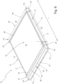
- the material provided for the manufacture of battery carrier B, Fig. 1 The sheet metal plate 1 shown is composed of a central section 2 and two side sections 3, 4.
- Each of the identically shaped side sections 3, 4 is connected, in particular welded, with its respective associated edge to one of the edges 5, 6 of the central section 2 aligned transversely to the longitudinal extension of the sheet metal plate 1.
- connection of the side sections 3, 4 with the central section 2 can be carried out using a variety of joining methods that have proven themselves in the state of the art for producing permanently tight and durable joint seams. These include in particular the laser welding or friction stir welding methods regularly used in the production of tailored welded blanks from aluminum sheets.
- the side sections 3, 4 are preferably aligned butt against the edges 5, 6 of the central section 2 in order to obtain joint seams S1, S2 that are as flat as possible.
- Fig. 1 the course of the outer edge of a circumferential edge section 8 of the battery carrier B to be produced from the sheet metal blank 1 is shown in dash-dotted lines.
- the central section 2 and the side sections 3,4 are each cut from 3 mm thick sheets.
- the central section consists of the high-strength aluminum material AA6063 in the T6 state, while the two ductile side sections 3,4 consist of the more ductile aluminum material AA5754 in the 0 state.
- the Al material AA6063 has a tensile strength Rm of 260 MPa and an elongation at break A of 7%.
- the Al material AA5754 in the 0 state has a tensile strength Rm of 230 MPa and an elongation at break A of 22%.
- the dashed line indicates Fig. 1
- a central base section 9 of the battery carrier B to be produced is delimited.
- the dotted lines indicate Fig. 1 a depression 10 formed in the bottom section 9 of the battery carrier B to be produced.
- the planar extent of the side sections 3, 4 and the central section 2 are selected such that the corner areas 11a - 11d of the side wall 12 of the battery carrier B to be produced, which are critical in terms of the forming behavior, are formed in the ductile side sections 3, 4.
- the sheet metal blank 1 is placed in a conventional press (not shown here), whose punch and die are shaped according to the desired shape of the battery carrier B.
- the press is used to form a blank R from the sheet metal blank 1, the basic shape of which already largely corresponds to the shape of the finished battery carrier B ( Fig. 2 ).
- the blank R therefore already has the central bottom section 9 formed from the central section 2 of the sheet metal plate 1 with a depression 10 formed in it, which runs around the bottom section 9. Side wall 12 and the edge portion 8 which projects laterally from the side wall 12 in the manner of a collar and surrounds the battery carrier B.
- the edge section 8 is cut along the line indicated by the dotted line ( Fig. 1 , 2 ) indicated outer edge of the edge section 8 is trimmed to remove excess sheet metal sections ( Fig. 3 ).
- the blank R is then subjected to a further forming process in which the areas of the edge section 8 which run parallel to the edges 5,6 or the joint seams S1,S2 are provided with a depression 16,17 extending over almost the entire width of the relevant areas ( Fig. 4 ).
- through holes 18 arranged at regular intervals are made in the depressions 16, 17 of the edge section 8, for example by means of a punching operation, which can be used for later fastening the finished battery carrier B to a vehicle body (not shown here) or, preferably, for fastening a cover (also not shown here) to the battery carrier B ( Fig. 5 ).
- the depression 10 is formed in the base section 9 and extends over almost the entire surface of the base section 9 except for an edge running around it.
- the side wall 12 runs around the base section 9.
- the side wall 12 is arranged at an angle to the base section 9 such that an angle ß of approximately 90° is enclosed between it and the base section 9.
- the side wall 12 comprises the high-strength Al material of the Bottom section 9 consisting of side wall sections 13,14, which extend along the long sides L1,L2 of the battery carrier B and are formed in one piece with the central bottom section 9 from the central section 2 of the sheet metal plate 1.
- the higher-strength side wall sections 13,14 of the side wall 12 are extended by short side wall sections 20,21,22,23, which are each formed from the side sections 3,4 of the sheet metal plate 1.
- the short, ductile side wall sections 20 - 23 meet in the corner region 11a - 11d assigned to them in each case a further ductile side wall section 24, 25 of the side wall 12, which is also formed from one of the ductile side sections 3, 4 and extends parallel to the joining seams S1, S2 along the respective transverse side Q1, Q2 of the battery carrier B.
- the corner areas 11a - 11d are arranged in the sections made of ductile Al material, while the central base section 9 and the side wall sections 13, 14 assigned to the long sides L1, L2, which, together with the base section 9, have to bear the main load of the battery elements to be accommodated by the battery carrier B, are made of high-strength Al material.
- the side wall sections 24, 25 made of the ductile Al material are shaped in such a way that they have a bottom-side first side wall zone 26, which is joined to the outer edge area of the bottom section 9 at its edge area associated with the bottom section 9, and a lateral extension of the bottom section 9, a second side wall zone 27 aligned at an angle with respect to its first side wall zone 26 and the bottom section 9, and a transition zone 28 via which the first side wall zone 26 merges into the second side wall zone 27.
- the inventive design and configuration of the battery carrier B makes it possible to ensure permanently tight shielding and an equally reliable, stable hold of battery elements (not shown here), which are arranged for use in the receiving space AR which the battery carrier B delimits.
Landscapes
- Chemical & Material Sciences (AREA)
- Engineering & Computer Science (AREA)
- Chemical Kinetics & Catalysis (AREA)
- Electrochemistry (AREA)
- General Chemical & Material Sciences (AREA)
- Transportation (AREA)
- Life Sciences & Earth Sciences (AREA)
- Mechanical Engineering (AREA)
- Inorganic Chemistry (AREA)
- Sustainable Development (AREA)
- Sustainable Energy (AREA)
- Power Engineering (AREA)
- Computer Hardware Design (AREA)
- Biophysics (AREA)
- Combustion & Propulsion (AREA)
- Aviation & Aerospace Engineering (AREA)
- Manufacturing & Machinery (AREA)
- Battery Mounting, Suspending (AREA)
- Sealing Battery Cases Or Jackets (AREA)
Claims (10)
- Porte-batterie prévu pour être fixé dans une zone de fond d'une structure porteuse d'un véhicule automobile à entraînement électrique, le porte-batterie (B) délimite, par une section de fond (9) et une paroi latérale (12) entourant la section de fond (9), un espace disponible (AR) pour au moins un élément de batterie à y positionner, et la paroi latérale (12) comporte au moins deux sections de paroi latérale (13, 14, 20-25) qui sont inclinées et orientées selon un angle (ß) supérieur à 0° par rapport à la section de fond (9) et qui se rejoignent dans une zone d'angle (11a-11d),caractériser par,la section de fond (9) du porte-batterie (B) est formée d'une seule pièce dans un premier matériau d'aluminium,
etque des sections de paroi latérale (20-23, 24, 25), qui partent de la paroi latérale (12) et qui se rejoignent dans au moins une des zones d'angle (11a-11d), sont formées, y compris la zone d'angle respective (11a-11d), d'une seule pièce dans un deuxième matériau d'aluminium qui présente un allongement à la rupture A supérieur à celui du premier matériau d'aluminium. - Porte-batterie selon la revendication 1, caractérisé en ce que le premier matériau d'aluminium présente une résistance à la traction Rm d'au moins 170 MPa et un allongement à la rupture A inférieur à 10 %.
- Porte-batterie selon la revendication 1 ou 2, caractérisé en ce que le deuxième matériau d'aluminium présente un allongement à la rupture A d'au moins 10 %.
- Porte-batterie selon l'une des revendications précédentes, caractérisé en ce que le porte-batterie (B) présente sur deux côtés opposés (L1, L2) respectivement une section de paroi latérale (13, 14) qui est formée d'une seule pièce avec la section de fond (9) dans le premier matériau d'aluminium, et en ce que respectivement l'une des sections de paroi latérale (20 - 23), qui ont entre elles une zone d'angle (11a - 11d) du porte-batterie (B), forme un prolongement de l'une des sections de paroi latérale (20 - 23) constituées du deuxième matériau d'aluminium de la section de fond (9).
- Porte-batterie selon la revendication 4, caractérisé en ce que la section de fond (9), vue de dessus, présente une forme de base rectangulaire, en ce que sur des côtés longitudinaux (L1, L2) mutuellement opposés de la section de fond (9) s'étend respectivement une section de paroi latérale (13, 14) composée du premier matériau d'aluminium, et en ce que les sections de paroi latérale (13, 14) composées du premier matériau d'aluminium sont prolongées, sur leurs côtés associés aux zones d'angle (11a-11d) du porte-batterie (B), par une section de paroi latérale composée du deuxième matériau d'aluminium, qui est assemblée avec elles.
- Porte-batterie selon la revendication 5, caractérisé en ce que les sections de paroi latérale (13, 14) à haute résistance s'étendent parallèlement l'une à l'autre.
- Porte-batterie selon l'une des revendications précédentes, caractérisé en ce que le premier matériau est un alliage d'aluminium de la série 6000, 7000 ou 8000 (AlMgSi) et le second matériau d'aluminium est un alliage d'aluminium de la série 3000, 4000 ou 5000 (AlMg).
- Procédé de fabrication d'un porte-batterie (B), prévu pour être fixé dans une zone de fond d'une structure porteuse d'un véhicule automobile à entraînement électrique, le porte-batterie (B) délimite, par une section de fond (9) et une paroi latérale (12) entourant la section de fond (9), un espace disponible (AR) pour au moins un élément de batterie à y positionner, et la paroi latérale (12) comporte au moins deux sections de paroi latérale (13, 14, 20-25) qui sont inclinées et orientées selon un angle (ß) supérieur à 0° par rapport à la section de fond (9) et qui se rejoignent dans une zone d'angle (11a-11d), comprenant les étapes de travail suivantes :a) Mise à disposition d'une platine de tôle (1) qui comprend une section centrale (2) qui est constituée d'un premier matériau d'aluminium et d'au moins deux sections latérales (3, 4) qui sont reliées par leur bord respectif associé à des bords opposés (5, 6) l'un à l'autre de la section centrale (2) et qui sont composées au moins par sections d'un deuxième matériau d'aluminium, pendant que le premier matériau d'aluminium présente un allongement à la rupture A qui est inférieur à l'allongement à la rupture A du deuxième matériau d'aluminium ;b) Déformation de la platine de tôle (1) en porte-batterie (B) en formant une section de fond (9) et une paroi latérale (12) du porte-batterie (B) entourant la section de fond (9), les zones de d'angle (11a-11d), dans lesquelles deux sections de paroi latérale (20-23, 24, 25) de la paroi latérale (12) se rejoignent, étant formées au cours de la déformation exclusivement à partir des sections (3, 4) de la platine de tôle (1) composées du deuxième matériau d'aluminium;c) Découpe optionnelle d'une zone de bord (8) de la paroi latérale périphérique (12) ;d) Déformation supplémentaire optionnelle de la paroi latérale (12) ou de la section de fond (9) pour former au moins un élément de forme supplémentaire (16, 17);e) Fabrication optionnelle d'ouvertures (18) dans le porte-batterie (B).
- Procédé selon la revendication 8, caractérisé en ce que la section centrale (2) de la platine de tôle (1) mis à disposition à l'étape de travail a) s'étend sur toute la largeur (W) de la platine de tôle (1), mais seulement sur une partie de la longueur (L) de la platine de tôle (1), et en ce que, lors de la déformation dans l'étape de travail b), les sections de bord de la section centrale (2) opposées l'une à l'autre et s'étendant entre les sections latérales ductiles (3, 4) de la platine de tôle (1) sont formées chacune en une section de paroi latérale (13, 14) à haute résistance du porte-batterie (B).
- Procédé selon la revendication 9, caractérisé en ce que les sections de paroi latérale (13, 14) composées du premier matériau d'aluminium s'étendent parallèlement l'une à l'autre.
Priority Applications (4)
| Application Number | Priority Date | Filing Date | Title |
|---|---|---|---|
| EP21202414.5A EP4167329B1 (fr) | 2021-10-13 | 2021-10-13 | Porte-batterie pour un véhicule électrique et procédé de fabrication d'un tel porte-batterie |
| PCT/IB2022/059671 WO2023062496A1 (fr) | 2021-10-13 | 2022-10-10 | Support de batterie pour un véhicule à propulsion électrique et procédé de fabrication d'un tel support de batterie |
| CN202280069089.XA CN118104021B (zh) | 2021-10-13 | 2022-10-10 | 用于电驱动车辆的电池载体及这种电池载体的制造方法 |
| US18/700,846 US12304297B2 (en) | 2021-10-13 | 2022-10-10 | Battery carrier for an electrically driven vehicle and method of manufacturing such a battery carrier |
Applications Claiming Priority (1)
| Application Number | Priority Date | Filing Date | Title |
|---|---|---|---|
| EP21202414.5A EP4167329B1 (fr) | 2021-10-13 | 2021-10-13 | Porte-batterie pour un véhicule électrique et procédé de fabrication d'un tel porte-batterie |
Publications (2)
| Publication Number | Publication Date |
|---|---|
| EP4167329A1 EP4167329A1 (fr) | 2023-04-19 |
| EP4167329B1 true EP4167329B1 (fr) | 2025-02-19 |
Family
ID=78179271
Family Applications (1)
| Application Number | Title | Priority Date | Filing Date |
|---|---|---|---|
| EP21202414.5A Active EP4167329B1 (fr) | 2021-10-13 | 2021-10-13 | Porte-batterie pour un véhicule électrique et procédé de fabrication d'un tel porte-batterie |
Country Status (4)
| Country | Link |
|---|---|
| US (1) | US12304297B2 (fr) |
| EP (1) | EP4167329B1 (fr) |
| CN (1) | CN118104021B (fr) |
| WO (1) | WO2023062496A1 (fr) |
Family Cites Families (9)
| Publication number | Priority date | Publication date | Assignee | Title |
|---|---|---|---|---|
| US20120161472A1 (en) | 2010-12-22 | 2012-06-28 | Tesla Motors, Inc. | System for Absorbing and Distributing Side Impact Energy Utilizing an Integrated Battery Pack |
| DE102011101586B4 (de) | 2011-05-13 | 2019-05-29 | Aleris Aluminum Koblenz Gmbh | Verfahren zur Herstellung eines geformten Karosseriebauteils für eine Fahrzeugkarosserie aus einem Tailored Blank |
| DE102017102685B4 (de) * | 2017-02-10 | 2021-11-04 | Benteler Automobiltechnik Gmbh | Batterieträger mit einer tiefgezogenen Wanne aus Aluminiumsowie Verfahren zu dessen Herstellung |
| US10886513B2 (en) * | 2017-05-16 | 2021-01-05 | Shape Corp. | Vehicle battery tray having tub-based integration |
| US10637023B2 (en) | 2017-09-06 | 2020-04-28 | Benteler Automobiltechnik Gmbh | Battery carrier for an electric motor vehicle |
| DE102017120533A1 (de) * | 2017-09-06 | 2019-03-07 | Benteler Automobiltechnik Gmbh | Batterieträger sowie Verfahren zur Herstellung des Batterieträgers |
| DE102019101637B4 (de) | 2019-01-23 | 2020-11-19 | Benteler Automobiltechnik Gmbh | Batterieträger mit eingeformter Sicke |
| JP7140735B2 (ja) * | 2019-10-18 | 2022-09-21 | 株式会社神戸製鋼所 | バッテリー収容ユニット |
| CN112531261A (zh) * | 2020-12-04 | 2021-03-19 | 东风(武汉)实业有限公司 | 一种异种材料混合工艺电池包 |
-
2021
- 2021-10-13 EP EP21202414.5A patent/EP4167329B1/fr active Active
-
2022
- 2022-10-10 CN CN202280069089.XA patent/CN118104021B/zh active Active
- 2022-10-10 US US18/700,846 patent/US12304297B2/en active Active
- 2022-10-10 WO PCT/IB2022/059671 patent/WO2023062496A1/fr not_active Ceased
Also Published As
| Publication number | Publication date |
|---|---|
| CN118104021A (zh) | 2024-05-28 |
| US20240408951A1 (en) | 2024-12-12 |
| CN118104021B (zh) | 2025-09-05 |
| EP4167329A1 (fr) | 2023-04-19 |
| WO2023062496A1 (fr) | 2023-04-20 |
| US12304297B2 (en) | 2025-05-20 |
Similar Documents
| Publication | Publication Date | Title |
|---|---|---|
| EP2729348B1 (fr) | Structure de plancher pour un véhicule | |
| DE102012100977B3 (de) | Energiespeichergefäß für ein Kraftfahrzeug mit Elektro- oder Hybridantrieb | |
| EP3544082B9 (fr) | Dispositif logement destiné de recevoir des moyens de stockage électriques et procédé de fabrication d'un dispositif logement | |
| DE102016117223B4 (de) | Fahrzeugtürschwellerverstärkung | |
| DE102016115037B4 (de) | Batteriekasten mit seitlicher Verstärkung | |
| DE102017104360A1 (de) | Batteriegehäuse | |
| WO2020038698A1 (fr) | Boîtier de batterie à élément de renforcement | |
| DE112018005556T5 (de) | Batterieträger-bodenbaugruppe für elektrofahrzeuge | |
| EP3465795A1 (fr) | Boîtier pour batterie de véhicule et procédé de fabrication d'un tel boîtier | |
| DE202018103481U1 (de) | Fahrzeugschwellerverstärkung | |
| DE102018131374B4 (de) | Modular aufgebauter Batterieträger | |
| DE112016000651T5 (de) | Fahrzeugkarosseriestruktur eines fahrzeugs | |
| EP4257391B1 (fr) | Porte-batterie monobloc, ainsi que procédé de moulage sous pression d'un porte-batterie monobloc | |
| DE102016121254A1 (de) | Batterieträger mit Toleranzausgleichselement | |
| EP4396894B1 (fr) | Ensemble boitier | |
| DE102020130361A1 (de) | Strukturelle verbesserungen eines elektrofahrzeugs | |
| DE102023118648A1 (de) | Eckschutz für batteriekasten eines elektrofahrzeugs | |
| DE102019207595B3 (de) | Batterieanordnung sowie Fahrzeug mit einer derartigen Batterieanordnung | |
| EP3942622B1 (fr) | Boitier de batterie, batterie de traction et vehicule avec un tel boitier de batterie | |
| DE102019213750B3 (de) | Flächenbauteil sowie elektrochemischer Speicher und/oder Kraftfahrzeug mit einem solchen Flächenbauteil | |
| EP4167329B1 (fr) | Porte-batterie pour un véhicule électrique et procédé de fabrication d'un tel porte-batterie | |
| DE102023118488A1 (de) | Batteriemontagehalterung für batteriekasten eines elektrofahrzeugs | |
| DE102015014641A1 (de) | Bodenblech für ein Fahrzeug, Bodenstruktur eines Fahrzeugs mit einem derartigen Bodenblech sowie Fahrzeug mit einer Bodenstruktur, welche ein derartiges Bodenblech aufweist | |
| DE102019203302B4 (de) | Deckelteil sowie Gehäuse mit einem derartigen Deckelteil | |
| DE102023124889B4 (de) | Bodenrahmen für eine Kraftfahrzeugkarosserie |
Legal Events
| Date | Code | Title | Description |
|---|---|---|---|
| PUAI | Public reference made under article 153(3) epc to a published international application that has entered the european phase |
Free format text: ORIGINAL CODE: 0009012 |
|
| STAA | Information on the status of an ep patent application or granted ep patent |
Free format text: STATUS: REQUEST FOR EXAMINATION WAS MADE |
|
| 17P | Request for examination filed |
Effective date: 20220330 |
|
| AK | Designated contracting states |
Kind code of ref document: A1 Designated state(s): AL AT BE BG CH CY CZ DE DK EE ES FI FR GB GR HR HU IE IS IT LI LT LU LV MC MK MT NL NO PL PT RO RS SE SI SK SM TR |
|
| RBV | Designated contracting states (corrected) |
Designated state(s): AL AT BE BG CH CY CZ DE DK EE ES FI FR GB GR HR HU IE IS IT LI LT LU LV MC MK MT NL NO PL PT RO RS SE SI SK SM TR |
|
| GRAP | Despatch of communication of intention to grant a patent |
Free format text: ORIGINAL CODE: EPIDOSNIGR1 |
|
| STAA | Information on the status of an ep patent application or granted ep patent |
Free format text: STATUS: GRANT OF PATENT IS INTENDED |
|
| INTG | Intention to grant announced |
Effective date: 20241014 |
|
| GRAS | Grant fee paid |
Free format text: ORIGINAL CODE: EPIDOSNIGR3 |
|
| GRAA | (expected) grant |
Free format text: ORIGINAL CODE: 0009210 |
|
| STAA | Information on the status of an ep patent application or granted ep patent |
Free format text: STATUS: THE PATENT HAS BEEN GRANTED |
|
| AK | Designated contracting states |
Kind code of ref document: B1 Designated state(s): AL AT BE BG CH CY CZ DE DK EE ES FI FR GB GR HR HU IE IS IT LI LT LU LV MC MK MT NL NO PL PT RO RS SE SI SK SM TR |
|
| REG | Reference to a national code |
Ref country code: GB Ref legal event code: FG4D Free format text: NOT ENGLISH |
|
| REG | Reference to a national code |
Ref country code: CH Ref legal event code: EP |
|
| REG | Reference to a national code |
Ref country code: IE Ref legal event code: FG4D Free format text: LANGUAGE OF EP DOCUMENT: GERMAN |
|
| REG | Reference to a national code |
Ref country code: DE Ref legal event code: R096 Ref document number: 502021006688 Country of ref document: DE |
|
| REG | Reference to a national code |
Ref country code: NL Ref legal event code: MP Effective date: 20250219 |
|
| PG25 | Lapsed in a contracting state [announced via postgrant information from national office to epo] |
Ref country code: RS Free format text: LAPSE BECAUSE OF FAILURE TO SUBMIT A TRANSLATION OF THE DESCRIPTION OR TO PAY THE FEE WITHIN THE PRESCRIBED TIME-LIMIT Effective date: 20250519 |
|
| PG25 | Lapsed in a contracting state [announced via postgrant information from national office to epo] |
Ref country code: FI Free format text: LAPSE BECAUSE OF FAILURE TO SUBMIT A TRANSLATION OF THE DESCRIPTION OR TO PAY THE FEE WITHIN THE PRESCRIBED TIME-LIMIT Effective date: 20250219 |
|
| PG25 | Lapsed in a contracting state [announced via postgrant information from national office to epo] |
Ref country code: PL Free format text: LAPSE BECAUSE OF FAILURE TO SUBMIT A TRANSLATION OF THE DESCRIPTION OR TO PAY THE FEE WITHIN THE PRESCRIBED TIME-LIMIT Effective date: 20250219 |
|
| PG25 | Lapsed in a contracting state [announced via postgrant information from national office to epo] |
Ref country code: ES Free format text: LAPSE BECAUSE OF FAILURE TO SUBMIT A TRANSLATION OF THE DESCRIPTION OR TO PAY THE FEE WITHIN THE PRESCRIBED TIME-LIMIT Effective date: 20250219 |
|
| REG | Reference to a national code |
Ref country code: LT Ref legal event code: MG9D |
|
| PG25 | Lapsed in a contracting state [announced via postgrant information from national office to epo] |
Ref country code: NO Free format text: LAPSE BECAUSE OF FAILURE TO SUBMIT A TRANSLATION OF THE DESCRIPTION OR TO PAY THE FEE WITHIN THE PRESCRIBED TIME-LIMIT Effective date: 20250519 Ref country code: IS Free format text: LAPSE BECAUSE OF FAILURE TO SUBMIT A TRANSLATION OF THE DESCRIPTION OR TO PAY THE FEE WITHIN THE PRESCRIBED TIME-LIMIT Effective date: 20250619 |
|
| PG25 | Lapsed in a contracting state [announced via postgrant information from national office to epo] |
Ref country code: NL Free format text: LAPSE BECAUSE OF FAILURE TO SUBMIT A TRANSLATION OF THE DESCRIPTION OR TO PAY THE FEE WITHIN THE PRESCRIBED TIME-LIMIT Effective date: 20250219 |
|
| PG25 | Lapsed in a contracting state [announced via postgrant information from national office to epo] |
Ref country code: HR Free format text: LAPSE BECAUSE OF FAILURE TO SUBMIT A TRANSLATION OF THE DESCRIPTION OR TO PAY THE FEE WITHIN THE PRESCRIBED TIME-LIMIT Effective date: 20250219 |
|
| PG25 | Lapsed in a contracting state [announced via postgrant information from national office to epo] |
Ref country code: LV Free format text: LAPSE BECAUSE OF FAILURE TO SUBMIT A TRANSLATION OF THE DESCRIPTION OR TO PAY THE FEE WITHIN THE PRESCRIBED TIME-LIMIT Effective date: 20250219 Ref country code: PT Free format text: LAPSE BECAUSE OF FAILURE TO SUBMIT A TRANSLATION OF THE DESCRIPTION OR TO PAY THE FEE WITHIN THE PRESCRIBED TIME-LIMIT Effective date: 20250620 |
|
| PG25 | Lapsed in a contracting state [announced via postgrant information from national office to epo] |
Ref country code: BG Free format text: LAPSE BECAUSE OF FAILURE TO SUBMIT A TRANSLATION OF THE DESCRIPTION OR TO PAY THE FEE WITHIN THE PRESCRIBED TIME-LIMIT Effective date: 20250219 Ref country code: GR Free format text: LAPSE BECAUSE OF FAILURE TO SUBMIT A TRANSLATION OF THE DESCRIPTION OR TO PAY THE FEE WITHIN THE PRESCRIBED TIME-LIMIT Effective date: 20250520 |
|
| PG25 | Lapsed in a contracting state [announced via postgrant information from national office to epo] |
Ref country code: SE Free format text: LAPSE BECAUSE OF FAILURE TO SUBMIT A TRANSLATION OF THE DESCRIPTION OR TO PAY THE FEE WITHIN THE PRESCRIBED TIME-LIMIT Effective date: 20250219 |
|
| PG25 | Lapsed in a contracting state [announced via postgrant information from national office to epo] |
Ref country code: SM Free format text: LAPSE BECAUSE OF FAILURE TO SUBMIT A TRANSLATION OF THE DESCRIPTION OR TO PAY THE FEE WITHIN THE PRESCRIBED TIME-LIMIT Effective date: 20250219 |
|
| PG25 | Lapsed in a contracting state [announced via postgrant information from national office to epo] |
Ref country code: DK Free format text: LAPSE BECAUSE OF FAILURE TO SUBMIT A TRANSLATION OF THE DESCRIPTION OR TO PAY THE FEE WITHIN THE PRESCRIBED TIME-LIMIT Effective date: 20250219 |
|
| PG25 | Lapsed in a contracting state [announced via postgrant information from national office to epo] |
Ref country code: IT Free format text: LAPSE BECAUSE OF FAILURE TO SUBMIT A TRANSLATION OF THE DESCRIPTION OR TO PAY THE FEE WITHIN THE PRESCRIBED TIME-LIMIT Effective date: 20250219 |
|
| PG25 | Lapsed in a contracting state [announced via postgrant information from national office to epo] |
Ref country code: EE Free format text: LAPSE BECAUSE OF FAILURE TO SUBMIT A TRANSLATION OF THE DESCRIPTION OR TO PAY THE FEE WITHIN THE PRESCRIBED TIME-LIMIT Effective date: 20250219 Ref country code: CZ Free format text: LAPSE BECAUSE OF FAILURE TO SUBMIT A TRANSLATION OF THE DESCRIPTION OR TO PAY THE FEE WITHIN THE PRESCRIBED TIME-LIMIT Effective date: 20250219 |
|
| PG25 | Lapsed in a contracting state [announced via postgrant information from national office to epo] |
Ref country code: RO Free format text: LAPSE BECAUSE OF FAILURE TO SUBMIT A TRANSLATION OF THE DESCRIPTION OR TO PAY THE FEE WITHIN THE PRESCRIBED TIME-LIMIT Effective date: 20250219 |
|
| PG25 | Lapsed in a contracting state [announced via postgrant information from national office to epo] |
Ref country code: SK Free format text: LAPSE BECAUSE OF FAILURE TO SUBMIT A TRANSLATION OF THE DESCRIPTION OR TO PAY THE FEE WITHIN THE PRESCRIBED TIME-LIMIT Effective date: 20250219 |
|
| REG | Reference to a national code |
Ref country code: DE Ref legal event code: R097 Ref document number: 502021006688 Country of ref document: DE |
|
| PLBE | No opposition filed within time limit |
Free format text: ORIGINAL CODE: 0009261 |
|
| STAA | Information on the status of an ep patent application or granted ep patent |
Free format text: STATUS: NO OPPOSITION FILED WITHIN TIME LIMIT |
|
| PGFP | Annual fee paid to national office [announced via postgrant information from national office to epo] |
Ref country code: DE Payment date: 20251020 Year of fee payment: 5 |
|
| PGFP | Annual fee paid to national office [announced via postgrant information from national office to epo] |
Ref country code: AT Payment date: 20260113 Year of fee payment: 5 |
|
| 26N | No opposition filed |
Effective date: 20251120 |