EP4167330A1 - Sekundärbatterie und verfahren zur herstellung davon - Google Patents
Sekundärbatterie und verfahren zur herstellung davon Download PDFInfo
- Publication number
- EP4167330A1 EP4167330A1 EP21824782.3A EP21824782A EP4167330A1 EP 4167330 A1 EP4167330 A1 EP 4167330A1 EP 21824782 A EP21824782 A EP 21824782A EP 4167330 A1 EP4167330 A1 EP 4167330A1
- Authority
- EP
- European Patent Office
- Prior art keywords
- pressure
- secondary battery
- formation process
- electrode assembly
- battery case
- Prior art date
- Legal status (The legal status is an assumption and is not a legal conclusion. Google has not performed a legal analysis and makes no representation as to the accuracy of the status listed.)
- Granted
Links
Images


Classifications
-
- H—ELECTRICITY
- H01—ELECTRIC ELEMENTS
- H01M—PROCESSES OR MEANS, e.g. BATTERIES, FOR THE DIRECT CONVERSION OF CHEMICAL ENERGY INTO ELECTRICAL ENERGY
- H01M50/00—Constructional details or processes of manufacture of the non-active parts of electrochemical cells other than fuel cells, e.g. hybrid cells
- H01M50/60—Arrangements or processes for filling or topping-up with liquids; Arrangements or processes for draining liquids from casings
- H01M50/609—Arrangements or processes for filling with liquid, e.g. electrolytes
- H01M50/627—Filling ports
-
- H—ELECTRICITY
- H01—ELECTRIC ELEMENTS
- H01M—PROCESSES OR MEANS, e.g. BATTERIES, FOR THE DIRECT CONVERSION OF CHEMICAL ENERGY INTO ELECTRICAL ENERGY
- H01M10/00—Secondary cells; Manufacture thereof
- H01M10/04—Construction or manufacture in general
- H01M10/049—Processes for forming or storing electrodes in the battery container
-
- H—ELECTRICITY
- H01—ELECTRIC ELEMENTS
- H01M—PROCESSES OR MEANS, e.g. BATTERIES, FOR THE DIRECT CONVERSION OF CHEMICAL ENERGY INTO ELECTRICAL ENERGY
- H01M10/00—Secondary cells; Manufacture thereof
- H01M10/04—Construction or manufacture in general
-
- H—ELECTRICITY
- H01—ELECTRIC ELEMENTS
- H01M—PROCESSES OR MEANS, e.g. BATTERIES, FOR THE DIRECT CONVERSION OF CHEMICAL ENERGY INTO ELECTRICAL ENERGY
- H01M10/00—Secondary cells; Manufacture thereof
- H01M10/04—Construction or manufacture in general
- H01M10/0413—Large-sized flat cells or batteries for motive or stationary systems with plate-like electrodes
-
- H—ELECTRICITY
- H01—ELECTRIC ELEMENTS
- H01M—PROCESSES OR MEANS, e.g. BATTERIES, FOR THE DIRECT CONVERSION OF CHEMICAL ENERGY INTO ELECTRICAL ENERGY
- H01M10/00—Secondary cells; Manufacture thereof
- H01M10/04—Construction or manufacture in general
- H01M10/0436—Small-sized flat cells or batteries for portable equipment
-
- H—ELECTRICITY
- H01—ELECTRIC ELEMENTS
- H01M—PROCESSES OR MEANS, e.g. BATTERIES, FOR THE DIRECT CONVERSION OF CHEMICAL ENERGY INTO ELECTRICAL ENERGY
- H01M10/00—Secondary cells; Manufacture thereof
- H01M10/04—Construction or manufacture in general
- H01M10/0468—Compression means for stacks of electrodes and separators
-
- H—ELECTRICITY
- H01—ELECTRIC ELEMENTS
- H01M—PROCESSES OR MEANS, e.g. BATTERIES, FOR THE DIRECT CONVERSION OF CHEMICAL ENERGY INTO ELECTRICAL ENERGY
- H01M10/00—Secondary cells; Manufacture thereof
- H01M10/04—Construction or manufacture in general
- H01M10/0481—Compression means other than compression means for stacks of electrodes and separators
-
- H—ELECTRICITY
- H01—ELECTRIC ELEMENTS
- H01M—PROCESSES OR MEANS, e.g. BATTERIES, FOR THE DIRECT CONVERSION OF CHEMICAL ENERGY INTO ELECTRICAL ENERGY
- H01M10/00—Secondary cells; Manufacture thereof
- H01M10/05—Accumulators with non-aqueous electrolyte
- H01M10/058—Construction or manufacture
- H01M10/0585—Construction or manufacture of accumulators having only flat construction elements, i.e. flat positive electrodes, flat negative electrodes and flat separators
-
- H—ELECTRICITY
- H01—ELECTRIC ELEMENTS
- H01M—PROCESSES OR MEANS, e.g. BATTERIES, FOR THE DIRECT CONVERSION OF CHEMICAL ENERGY INTO ELECTRICAL ENERGY
- H01M4/00—Electrodes
- H01M4/02—Electrodes composed of, or comprising, active material
- H01M4/04—Processes of manufacture in general
-
- H—ELECTRICITY
- H01—ELECTRIC ELEMENTS
- H01M—PROCESSES OR MEANS, e.g. BATTERIES, FOR THE DIRECT CONVERSION OF CHEMICAL ENERGY INTO ELECTRICAL ENERGY
- H01M4/00—Electrodes
- H01M4/02—Electrodes composed of, or comprising, active material
- H01M4/04—Processes of manufacture in general
- H01M4/0438—Processes of manufacture in general by electrochemical processing
- H01M4/044—Activating, forming or electrochemical attack of the supporting material
- H01M4/0445—Forming after manufacture of the electrode, e.g. first charge, cycling
- H01M4/0447—Forming after manufacture of the electrode, e.g. first charge, cycling of complete cells or cells stacks
-
- H—ELECTRICITY
- H01—ELECTRIC ELEMENTS
- H01M—PROCESSES OR MEANS, e.g. BATTERIES, FOR THE DIRECT CONVERSION OF CHEMICAL ENERGY INTO ELECTRICAL ENERGY
- H01M50/00—Constructional details or processes of manufacture of the non-active parts of electrochemical cells other than fuel cells, e.g. hybrid cells
- H01M50/10—Primary casings; Jackets or wrappings
-
- H—ELECTRICITY
- H01—ELECTRIC ELEMENTS
- H01M—PROCESSES OR MEANS, e.g. BATTERIES, FOR THE DIRECT CONVERSION OF CHEMICAL ENERGY INTO ELECTRICAL ENERGY
- H01M50/00—Constructional details or processes of manufacture of the non-active parts of electrochemical cells other than fuel cells, e.g. hybrid cells
- H01M50/10—Primary casings; Jackets or wrappings
- H01M50/102—Primary casings; Jackets or wrappings characterised by their shape or physical structure
- H01M50/107—Primary casings; Jackets or wrappings characterised by their shape or physical structure having curved cross-section, e.g. round or elliptic
-
- H—ELECTRICITY
- H01—ELECTRIC ELEMENTS
- H01M—PROCESSES OR MEANS, e.g. BATTERIES, FOR THE DIRECT CONVERSION OF CHEMICAL ENERGY INTO ELECTRICAL ENERGY
- H01M50/00—Constructional details or processes of manufacture of the non-active parts of electrochemical cells other than fuel cells, e.g. hybrid cells
- H01M50/10—Primary casings; Jackets or wrappings
- H01M50/116—Primary casings; Jackets or wrappings characterised by the material
-
- H—ELECTRICITY
- H01—ELECTRIC ELEMENTS
- H01M—PROCESSES OR MEANS, e.g. BATTERIES, FOR THE DIRECT CONVERSION OF CHEMICAL ENERGY INTO ELECTRICAL ENERGY
- H01M50/00—Constructional details or processes of manufacture of the non-active parts of electrochemical cells other than fuel cells, e.g. hybrid cells
- H01M50/40—Separators; Membranes; Diaphragms; Spacing elements inside cells
- H01M50/46—Separators, membranes or diaphragms characterised by their combination with electrodes
-
- H—ELECTRICITY
- H01—ELECTRIC ELEMENTS
- H01M—PROCESSES OR MEANS, e.g. BATTERIES, FOR THE DIRECT CONVERSION OF CHEMICAL ENERGY INTO ELECTRICAL ENERGY
- H01M50/00—Constructional details or processes of manufacture of the non-active parts of electrochemical cells other than fuel cells, e.g. hybrid cells
- H01M50/60—Arrangements or processes for filling or topping-up with liquids; Arrangements or processes for draining liquids from casings
- H01M50/609—Arrangements or processes for filling with liquid, e.g. electrolytes
- H01M50/627—Filling ports
- H01M50/636—Closing or sealing filling ports, e.g. using lids
-
- H—ELECTRICITY
- H01—ELECTRIC ELEMENTS
- H01M—PROCESSES OR MEANS, e.g. BATTERIES, FOR THE DIRECT CONVERSION OF CHEMICAL ENERGY INTO ELECTRICAL ENERGY
- H01M10/00—Secondary cells; Manufacture thereof
- H01M10/42—Methods or arrangements for servicing or maintenance of secondary cells or secondary half-cells
-
- H—ELECTRICITY
- H01—ELECTRIC ELEMENTS
- H01M—PROCESSES OR MEANS, e.g. BATTERIES, FOR THE DIRECT CONVERSION OF CHEMICAL ENERGY INTO ELECTRICAL ENERGY
- H01M50/00—Constructional details or processes of manufacture of the non-active parts of electrochemical cells other than fuel cells, e.g. hybrid cells
- H01M50/60—Arrangements or processes for filling or topping-up with liquids; Arrangements or processes for draining liquids from casings
- H01M50/609—Arrangements or processes for filling with liquid, e.g. electrolytes
-
- Y—GENERAL TAGGING OF NEW TECHNOLOGICAL DEVELOPMENTS; GENERAL TAGGING OF CROSS-SECTIONAL TECHNOLOGIES SPANNING OVER SEVERAL SECTIONS OF THE IPC; TECHNICAL SUBJECTS COVERED BY FORMER USPC CROSS-REFERENCE ART COLLECTIONS [XRACs] AND DIGESTS
- Y02—TECHNOLOGIES OR APPLICATIONS FOR MITIGATION OR ADAPTATION AGAINST CLIMATE CHANGE
- Y02E—REDUCTION OF GREENHOUSE GAS [GHG] EMISSIONS, RELATED TO ENERGY GENERATION, TRANSMISSION OR DISTRIBUTION
- Y02E60/00—Enabling technologies; Technologies with a potential or indirect contribution to GHG emissions mitigation
- Y02E60/10—Energy storage using batteries
-
- Y—GENERAL TAGGING OF NEW TECHNOLOGICAL DEVELOPMENTS; GENERAL TAGGING OF CROSS-SECTIONAL TECHNOLOGIES SPANNING OVER SEVERAL SECTIONS OF THE IPC; TECHNICAL SUBJECTS COVERED BY FORMER USPC CROSS-REFERENCE ART COLLECTIONS [XRACs] AND DIGESTS
- Y02—TECHNOLOGIES OR APPLICATIONS FOR MITIGATION OR ADAPTATION AGAINST CLIMATE CHANGE
- Y02P—CLIMATE CHANGE MITIGATION TECHNOLOGIES IN THE PRODUCTION OR PROCESSING OF GOODS
- Y02P70/00—Climate change mitigation technologies in the production process for final industrial or consumer products
- Y02P70/50—Manufacturing or production processes characterised by the final manufactured product
Definitions
- the present invention relates to a secondary battery and a method for manufacturing the same, and more particularly, to a secondary battery in which a swelling phenomenon of an electrode assembly is prevented, and a plurality of unit cells are be laminated due to a pressure inside a battery case, and a method for manufacturing the same.
- secondary batteries include nickel-cadmium batteries, nickel-hydrogen batteries, lithium ion batteries, and lithium ion polymer batteries.
- Such a secondary battery is being applied to be used in small-sized products such as digital cameras, P-DVDs, MP3Ps, mobile phones, PDAs, portable game devices, power tools, E-bikes, and the like as well as large-sized products requiring high power such as electric vehicles and hybrid vehicles, power storage devices for storing surplus power or renewable energy, and backup power storage devices.
- electrode active material slurry is applied to a positive electrode collector and a negative electrode collector to manufacture a positive electrode (cathode) and a negative electrode (anode). Then, the electrodes are laminated on both sides of a separator form an electrode assembly. Also, the electrode assembly is accommodated in a battery case, and then the battery case is sealed after an electrolyte is injected therein.
- Such a secondary battery is classified into a pouch type secondary battery and a can type secondary battery according to a material of a case accommodating the electrode assembly.
- the electrode assembly is accommodated in a pouch made of a flexible polymer material having a variable shape.
- an electrode assembly is accommodated in a case made of a metal or plastic material having a predetermined shape.
- the can type secondary battery is classified into a prismatic type secondary battery in which the case has a polygonal shape and a cylinder type secondary battery in which the case has a cylindrical shape according to the shape of the case.
- an injection hole is sealed after an electrolyte is injected into a pouch type battery case, and then, a formation process is performed. Also, a hole is punched in a degassing part formed at one side of the pouch to perform a degassing process for discharging a gas generated in the battery. Thereafter, the pouch is re-sealed, and the degassing part is removed.
- the secondary battery since the formation process is performed after the injection hole is completely closed, a charging rate may be high, and the gas may be quickly discharged.
- the secondary battery may be manufactured within a predetermined process time.
- an injection hole may not be completely closed. If the formation process is performed after the injection hole is completely closed, unlike the pouch type battery case, if a volume of the battery case is expanded once due to generation of a gas, it is very difficult to return to its original state after the degassing process.
- the can type battery case is made of a material having rigidity such as a metal or plastic, it is impossible to reseal the battery case after the degassing hole is punched. Therefore, before closing the injection hole, a primary electrolyte is first injected, and a formation process is performed in a dry room to prevent moisture from being permeated. Then, after the gas is discharged to some extent, a secondary electrolyte is injected, and the injection hole is closed.
- the injection hole has to be closed in a state in which the gas is not completely discharged.
- the gas is discharged, and the gas partially remains within the case.
- a swelling phenomenon in which the electrode assembly swells by the remaining gas occurs, there is a problem in that the manufactured secondary battery increases in thickness.
- An object of the present invention is to provide a method for manufacturing a secondary battery in which a swelling phenomenon of an electrode assembly is prevented, and a plurality of unit cells are be laminated due to a pressure inside a battery case.
- a method for manufacturing a secondary battery according to an embodiment of the present invention for achieving the above object includes: accommodating an electrode assembly, in which electrodes and separators are alternately stacked, in a can type battery case; primarily injecting an electrolyte through an injection hole; applying a pressure to the battery case while performing a formation process in a state in which the injection hole is opened; secondarily injecting the electrolyte through the injection hole; and closing the injection hole.
- the electrode assembly may be a stack type electrode assembly in which at least portions of the electrodes and the separators are laminated.
- the applying of the pressure while performing the formation process may include: applying a primary pressure as a first pressure while performing a primary formation process; and applying a secondary pressure as a second pressure that is greater than the first pressure while performing a secondary formation process.
- the first pressure may be 0.5 kgf/cm 2 to 1 kgf/cm 2
- the second pressure may be 4.5 kgf/cm 2 to 10 kgf/cm 2 .
- a charging rate may be 23% or less.
- a charging rate may be 70% or less.
- the battery case may be heated.
- the battery case may be heated at a temperature of 55° to 65°.
- the method may further include performing aging after the primarily injecting of the electrolyte and before the applying of the pressure while performing the formation process.
- a temperature for the aging may be 20° to 30°.
- a gas remaining in the battery case may be discharged to the outside.
- a secondary battery according to an embodiment of the present invention for achieving the above object includes: a stack type electrode assembly, in which electrodes and separators are alternately stacked, wherein at least portions of the electrodes and the separators are laminated with each other; and a can type battery case in which the electrode assembly is accommodated and which has a constant outer appearance.
- the gas may be effectively discharged to the outside to prevent the electrode assembly from swelling and to shorten the manufacturing process.
- the plurality of unit cells may be laminated due to the pressure inside the battery case.
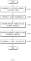
- FIG. 1 is a flowchart illustrating a method for manufacturing a secondary battery 1 according to an embodiment of the present invention.
- a gas may be effectively discharged to the outside to prevent the electrode assembly from swelling and to shorten a manufacturing process.
- a stack type electrode assembly not a jelly roll type electrode assembly
- a plurality of unit cells may be laminated due to a pressure inside a battery case 12.
- a method for manufacturing a secondary battery 1 includes: a process of accommodating an electrode assembly, in which electrodes and separators are alternately stacked, in a can type battery case 12; a process of primarily injecting an electrolyte through an injection hole 111; a process of applying a pressure to the battery case 12 while performing a formation process in a state in which the injection hole 111 is opened; a process of secondarily injecting the electrolyte through the injection hole 111, and a process of closing the injection hole 111.
- the process of applying the pressure while performing the formation process may include a process of primarily applying a first pressure while performing a primary formation process; and a process of secondarily applying a second pressure that is greater than the first pressure while performing a secondary formation process.
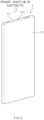
- FIG. 2 is a schematic view illustrating a state in which the electrolyte is primarily injected into the secondary battery 1 according to an embodiment of the prevent invention.
- a method for manufacturing the secondary battery 1 according to an embodiment of the present invention is largely classified into three processes such as an electrode plate process, an assembly process, and a formation process.
- the electrode plate process is a process of manufacturing a positive electrode and a negative electrode.
- an active material may be applied to a base material to manufacture the positive electrode and the negative electrode.
- the assembly process is a process of assembling the secondary battery 1.
- the positive and negative electrodes, which are manufactured as described above, and the separators may be alternately stacked to manufacture the electrode assembly.
- the electrode assembly is classified into a jelly roll type electrode assembly formed by stacking a long electrode sheet and separator sheet and then winding the sheets and a stack type electrode assembly in which at least portions of the plurality of electrodes and separators are laminated to be bonded to each other according to shapes of the electrode assembly.
- the jelly roll type electrode assembly is used in a can type secondary battery, and a stack type electrode assembly is used in a pouch type secondary battery.
- a gas may partially remain inside the battery case.
- the jelly roll type electrode assembly since the laminating is not performed, there is no bonding between the electrode and the separator, and also, even if a gas is generated after the formation process, the gas may be smoothly discharged to the outside, and thus, since an amount of gag trapped in the battery case is small, a swelling phenomenon does not occur often.
- the stacked electrode assembly since at least a portion is bonded by laminating the electrodes and the separators, an amount of gas trapped between the electrodes and the separators may be large when the formation process is performed.
- the formation process is performed after the battery case is completely sealed.
- the gas may be smoothly discharged to the outside through a separate degassing process to be later.
- the stack type electrode assembly having high energy density and low possibility of occurrence of damage may be used.
- the stack type electrode assembly in which at least a portion of the electrodes and the separators is laminated is used. Therefore, the energy density is higher, and the possibility of occurrence of damage is low when compared to the can type secondary battery according to the related art. However, the gas generated in the formation process has to be more smoothly discharged.
- the stack type electrode assembly is accommodated therein through an opening of the can type battery case 12, and the opening of the battery case 12 is covered (S101).
- a top cap assembly 11 or the like may be used.
- the opening of the battery case 12 may be covered by welding an outer wall of the battery case 12 to the top cap assembly 11.
- the battery case 12 is made of a material having rigidity, such as a metal or plastic and thus is constantly maintained in outer appearance thereof.
- a prismatic type battery having a polyhedron or polygonal column shape is illustrated in FIG. 2
- the embodiment of the present invention is not limited thereto.
- the battery case 12 may be a cylinder type battery having a cylindrical shape. That is, if the battery case 12 is provided in the can type having a predetermined shape, various kinds of secondary batteries 1 may be provided without limitation.
- the electrolyte is primarily injected through the injection hole 111 formed in the battery case 12 (S102).
- S102 the electrolyte
- the electrolyte injected into the battery case 12 may be discharged together with the gas to the outside by overflow.
- a pressure may be lowered so that the surroundings are close to a vacuum state. Therefore, impregnability of the electrolyte may be further improved.
- the formation process is a process of forming an SEI layer on a surface of electrode plates of the electrode assembly to have electric charges.
- the secondary battery 1 may be finally charged through the formation process to supply power.
- the formation process may be performed without closing the injection hole 111.
- the formation process may be performed in a dry room.
- an aging process is a process of storing the assembled secondary battery 1 for a predetermined time at specific temperature and humidity.
- the electrolyte is sufficiently dispersed in the secondary battery 1 to optimize movement of ions.
- the temperature for performing such the aging process may be between 20° to 30°, in particular, preferably 25°.
- FIG. 3 is a schematic view illustrating a state in which the can type secondary battery swells.
- a gas may be generated inside the battery case 12.
- the injection hole 111 is not closed, but is maintained in an open state.
- the injection hole 111 may be closed so that the gas partially remain inside the battery case 12.
- an amount of gas trapped between the electrodes and the separators in the gas generated by performing the formation process may be large.
- a swelling phenomenon in which the electrode assembly swells by the gas occurs, as illustrated in FIG. 3 , a problem in that the secondary battery 1 increases in thickness.
- FIG. 4 is a schematic view illustrating a state in which the secondary battery 1 is pressed by a jig according to an embodiment of the present invention.
- a pressure is applied to the secondary battery 1 by using a jig 2.
- a first pressure may be primarily applied while performing a first formation process (S103), and then a second pressure that is greater than the first pressure may be secondarily applied while performing a second formation process (S104).
- the first pressure for applying the primary pressure may be relatively weak that is enough to prevent the outer appearance of the secondary battery 1 from being deformed only by a large amount of gas. That is, the first pressure may be 0.5 kgf/cm 2 to 1 kgf/cm 2 , in particular, preferably 0.5 kgf/cm 2 to 0.7 kgf/cm 2 .
- the first pressure is less than 0.5 kgf/cm 2 , even if the injection hole 111 is opened, the outer appearance of the secondary battery 1 may be deformed by the large amount of gas. Conversely, if the first pressure is greater than 1 kgf/cm 2 , there is no significantly different effect compared to the case of the pressure of 1 kgf/cm 2 .
- the secondary pressure is applied while performing a secondary formation process.
- the second pressure for applying the secondary pressure may be relatively strong that is enough to allow the gas to remain inside the battery case 12 or to maximally discharge the trapped gas. That is, the second pressure may be 4.5 kgf/cm 2 to 10 kgf/cm 2 , in particular, preferably 5.0 kgf/cm 2 to 7.0 kgf/cm 2 . If the second pressure is less than 4.5 kgf/cm 2 , the remaining or trapped gas may not be smoothly discharged to the outside. Conversely, if the second pressure is greater than 10 kgf/cm 2 , the can type battery case 12 may be recessed inward and deformed, and also, the electrolyte inside the battery case 12 may be discharged to the outside.
- the secondary battery 1 when a pressure is applied while performing the formation process as described above, the secondary battery 1 may be heated at a high temperature.
- the electrode assembly according to embodiments of the present invention is the stack type electrode assembly, and the stack type electrode assembly is formed by laminating at least a portion of the plurality of electrodes and separators.
- a non-laminated portion may exist, and as the electrode assembly increases in thickness, the non-laminated portion may increase.
- the stack type electrode assembly includes a lamination & stack type electrode assembly, in which unit cells are stacked after the unit cells are manufactured, and a stack & folding type electrode assembly, in which a plurality of unit cells are attached to be spaced apart from each other on one surface of a separator sheet that is a long length in one direction, and then, the separator sheet is repeatedly folded from one end thereof in the same direction.
- the electrodes and the separators inside the unit cells may be easily bonded by a laminating process, but after the unit cells are stacked, the electrodes and the separators of the unit cells may not be easily bonded through the laminating process because the electrodes and the separators are already thick.
- the secondary battery 1 when a pressure is applied while performing the formation process, the secondary battery 1 may be heated at a high temperature to discharge the remaining or trapped gas to the outside and also to additionally laminate non-laminated portion of the electrode assembly.
- the secondary battery 1 it is preferable to heat the secondary battery 1, particularly, when applying the secondary pressure as the relatively strong second pressure, and the temperature is heated to 55° to 65°. If the heating temperature is lower than 55°, an effect of the laminating may be reduced. Conversely, if the heating temperature is higher than 65°, the internal electrolyte may be evaporated, or the electrode assembly may be damaged.
- the jig 2 for pressing the secondary battery 1 has a flat pressing surface to uniformly press the entire surface of both surfaces of the secondary battery 1. Also, as illustrated in FIG. 4 , the jig 2 moves toward the secondary battery 1 to apply a pressure. In addition, after a predetermined time elapses, the jig 2 moves in a direction opposite to the secondary battery 1 to remove the pressure applied to the secondary battery 1. The jig 2 may also reciprocate in a vertical direction and a horizontal direction. Therefore, the pressure may be intensively applied to any position of the battery case 12 or an appropriate point intended by a user.
- a piston or the like may be connected to an opposite surface of the pressing surface of the jig 2.
- the jig 2 may move by the piston in various manners without limitation, such as a mechanical system, a hydraulic system, and the like.
- a charging rate When performing the primary formation process, a charging rate may be approximately 23% or less, preferably 170 or less. In addition, when performing the secondary formation process, the charging rate may be higher than the above-described charging rate, for example, about 70% or less, preferably 65% or less.
- the formation process is performed in a state in which the injection hole 111 of the can type secondary battery 1 is opened, and the gas may be discharged to the outside through the injection hole 111.
- the gas since the secondary battery 1 is pressed while performing the formation process, the gas may be discharged to the outside as much as possible.
- the gas remaining in the battery case 12 may be reduced to be minimized, thereby preventing the secondary battery 1 from increasing in thickness.
- a stack type electrode assembly not a jelly roll type electrode assembly, is accommodated in a can type battery case 12
- a plurality of unit cells may be laminated due to a pressure 12 inside a battery case.
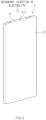
- FIG. 5 is a schematic view illustrating a state in which the electrolyte is secondarily injected into the secondary battery 1 according to an embodiment of the prevent invention.
- the electrolyte is injected secondarily.
- the pressure may be lowered to be close to a vacuum state around the surroundings, or an injection device for secondarily injecting the electrolyte may suction the gas while injecting the electrolyte. Therefore, the gas still remaining inside the battery case 12 may be further discharged.
- the injection hole 111 is closed.
- the secondary battery 1 according to an embodiment of the present invention may be completely manufactured.
Landscapes
- Chemical & Material Sciences (AREA)
- Chemical Kinetics & Catalysis (AREA)
- Electrochemistry (AREA)
- General Chemical & Material Sciences (AREA)
- Engineering & Computer Science (AREA)
- Manufacturing & Machinery (AREA)
- Secondary Cells (AREA)
Applications Claiming Priority (2)
| Application Number | Priority Date | Filing Date | Title |
|---|---|---|---|
| KR1020200072599A KR102957144B1 (ko) | 2020-06-15 | 이차 전지 및 그의 제조 방법 | |
| PCT/KR2021/007400 WO2021256804A1 (ko) | 2020-06-15 | 2021-06-14 | 이차 전지 및 그의 제조 방법 |
Publications (3)
| Publication Number | Publication Date |
|---|---|
| EP4167330A1 true EP4167330A1 (de) | 2023-04-19 |
| EP4167330A4 EP4167330A4 (de) | 2024-04-10 |
| EP4167330B1 EP4167330B1 (de) | 2025-11-19 |
Family
ID=79164316
Family Applications (1)
| Application Number | Title | Priority Date | Filing Date |
|---|---|---|---|
| EP21824782.3A Active EP4167330B1 (de) | 2020-06-15 | 2021-06-14 | Sekundärbatterie und verfahren zur herstellung |
Country Status (5)
| Country | Link |
|---|---|
| US (1) | US20230253609A1 (de) |
| EP (1) | EP4167330B1 (de) |
| CN (1) | CN115917810A (de) |
| ES (1) | ES3063581T3 (de) |
| WO (1) | WO2021256804A1 (de) |
Cited By (1)
| Publication number | Priority date | Publication date | Assignee | Title |
|---|---|---|---|---|
| SE2330370A1 (en) * | 2023-08-28 | 2025-03-01 | Novo Energy R&D Ab | Using compressive forces during battery cell manufacturing |
Families Citing this family (1)
| Publication number | Priority date | Publication date | Assignee | Title |
|---|---|---|---|---|
| US20230155163A1 (en) * | 2021-11-15 | 2023-05-18 | Sk On Co., Ltd. | Formation Method For Secondary Battery |
Family Cites Families (15)
| Publication number | Priority date | Publication date | Assignee | Title |
|---|---|---|---|---|
| KR100416093B1 (ko) * | 2001-05-23 | 2004-01-24 | 삼성에스디아이 주식회사 | 리튬전지의 제조방법 |
| JP2003217671A (ja) * | 2002-01-18 | 2003-07-31 | At Battery:Kk | 密閉型電池の製造方法と密閉型電池のシール性評価方法 |
| JP4383781B2 (ja) * | 2002-08-21 | 2009-12-16 | 株式会社東芝 | 電池の製造方法 |
| FR2936653B1 (fr) * | 2008-09-30 | 2011-02-11 | Commissariat Energie Atomique | Accumulateur a electrolyte liquide et procede de remplissage |
| KR101002783B1 (ko) | 2010-05-27 | 2011-01-10 | (주)벡셀 | 전해액 주입방법 |
| JP5683938B2 (ja) * | 2010-12-22 | 2015-03-11 | 日立オートモティブシステムズ株式会社 | 二次電池の製造方法および電解液注入装置 |
| CN103988357B (zh) * | 2011-11-24 | 2017-09-26 | 丰田自动车株式会社 | 非水电解液二次电池的制造方法 |
| US9859569B2 (en) * | 2012-02-07 | 2018-01-02 | Nissan Motor Co., Ltd. | Method and device for manufacturing film-wrapped electrical device |
| KR101629482B1 (ko) * | 2013-07-31 | 2016-06-10 | 주식회사 엘지화학 | 활성화 공정 중 전지를 가압하는 리튬 이차전지의 제조방법 |
| KR20160068929A (ko) * | 2013-10-15 | 2016-06-15 | 도요타지도샤가부시키가이샤 | 이차 전지의 제조 방법 |
| KR101750089B1 (ko) * | 2014-06-09 | 2017-06-21 | 주식회사 엘지화학 | 각형 전지용 탑 캡 및 이를 포함하는 전지팩 |
| KR101905246B1 (ko) * | 2014-09-30 | 2018-10-05 | 주식회사 엘지화학 | 리튬 이차전지의 제조방법 |
| KR20170101582A (ko) * | 2016-02-29 | 2017-09-06 | 주식회사 엘지화학 | 활성화 공정 중 압력을 변화시키는 과정을 포함하는 리튬 이차전지의 제조 방법 |
| KR102586807B1 (ko) * | 2017-11-24 | 2023-10-10 | (주)이티에스 | 전해질 주입장치 및 전해액 주입방법 |
| KR102740245B1 (ko) * | 2018-11-05 | 2024-12-06 | 주식회사 엘지에너지솔루션 | 전지 제조용 가스 제거기 및 이를 이용한 전지 제조 방법 |
-
2021
- 2021-06-14 EP EP21824782.3A patent/EP4167330B1/de active Active
- 2021-06-14 US US18/010,237 patent/US20230253609A1/en active Pending
- 2021-06-14 CN CN202180042931.6A patent/CN115917810A/zh active Pending
- 2021-06-14 WO PCT/KR2021/007400 patent/WO2021256804A1/ko not_active Ceased
- 2021-06-14 ES ES21824782T patent/ES3063581T3/es active Active
Cited By (2)
| Publication number | Priority date | Publication date | Assignee | Title |
|---|---|---|---|---|
| SE2330370A1 (en) * | 2023-08-28 | 2025-03-01 | Novo Energy R&D Ab | Using compressive forces during battery cell manufacturing |
| WO2025045820A1 (en) * | 2023-08-28 | 2025-03-06 | Novo Energy R&D Ab | Method for manufacturing a battery cell using compressive forces |
Also Published As
| Publication number | Publication date |
|---|---|
| EP4167330A4 (de) | 2024-04-10 |
| CN115917810A (zh) | 2023-04-04 |
| US20230253609A1 (en) | 2023-08-10 |
| KR20210155281A (ko) | 2021-12-22 |
| EP4167330B1 (de) | 2025-11-19 |
| WO2021256804A1 (ko) | 2021-12-23 |
| ES3063581T3 (en) | 2026-04-17 |
Similar Documents
| Publication | Publication Date | Title |
|---|---|---|
| KR102256599B1 (ko) | 가압 지그 및 이를 이용한 이차전지 제조 방법 | |
| US9548517B2 (en) | Battery cell of stair-like structure | |
| US9741974B2 (en) | Battery cell having round corner | |
| KR101382554B1 (ko) | 휘어진 형상의 전지셀 및 이를 포함하는 전지팩 | |
| KR102045246B1 (ko) | 탈기 과정의 공정성이 향상된 이차전지의 제조 방법 | |
| KR102820685B1 (ko) | 이차전지 제조방법 및 이차전지 제조용 프리 디개스 장치 | |
| KR101596269B1 (ko) | 안전성이 향상된 신규한 구조의 전지셀 | |
| US9853294B2 (en) | Secondary battery and manufacturing method thereof | |
| US10050255B2 (en) | Rechargeable battery and method of manufacturing the same | |
| KR101838315B1 (ko) | 파우치형 리튬 이차전지의 제조 방법 | |
| US11050103B2 (en) | Pouch cell and method of forming same | |
| KR20110073405A (ko) | 휘어진 형상의 전지셀 및 이를 포함하는 전지팩 | |
| US9553298B2 (en) | Pouch type case, battery cell, and method of manufacturing battery cell | |
| EP2637238B1 (de) | Wiederaufladbare Batterie und Batteriemodul | |
| KR20210089027A (ko) | 이차전지 제조장치 및 이차전지 제조방법 | |
| EP4167330A1 (de) | Sekundärbatterie und verfahren zur herstellung davon | |
| KR20170094669A (ko) | 각형 이차전지의 제조 방법 및 제조 장치 | |
| US20140227573A1 (en) | Electric device having round corner | |
| KR102957144B1 (ko) | 이차 전지 및 그의 제조 방법 | |
| KR20240027551A (ko) | 리튬 이차전지의 활성화 방법 | |
| KR102849371B1 (ko) | 파우치형 전지 케이스 및 이를 포함하는 파우치형 이차 전지, 파우치형 전지 케이스의 제조 방법, 그리고 파우치형 전지 케이스 제조용 성형 지그 | |
| JP2025515976A (ja) | パウチ型電池ケース及びそれを含むパウチ型二次電池、パウチ型電池ケースの製造方法、そしてパウチ型電池ケース製造用成形ジグ | |
| CN121889902A (zh) | 加压装置及加压方法 | |
| KR20230080583A (ko) | 확장된 가스 포켓부를 포함하는 파우치형 전지케이스 및 이를 이용한 파우치형 이차전지의 제조방법 |
Legal Events
| Date | Code | Title | Description |
|---|---|---|---|
| STAA | Information on the status of an ep patent application or granted ep patent |
Free format text: STATUS: THE INTERNATIONAL PUBLICATION HAS BEEN MADE |
|
| PUAI | Public reference made under article 153(3) epc to a published international application that has entered the european phase |
Free format text: ORIGINAL CODE: 0009012 |
|
| STAA | Information on the status of an ep patent application or granted ep patent |
Free format text: STATUS: REQUEST FOR EXAMINATION WAS MADE |
|
| 17P | Request for examination filed |
Effective date: 20221208 |
|
| AK | Designated contracting states |
Kind code of ref document: A1 Designated state(s): AL AT BE BG CH CY CZ DE DK EE ES FI FR GB GR HR HU IE IS IT LI LT LU LV MC MK MT NL NO PL PT RO RS SE SI SK SM TR |
|
| DAV | Request for validation of the european patent (deleted) | ||
| DAX | Request for extension of the european patent (deleted) | ||
| A4 | Supplementary search report drawn up and despatched |
Effective date: 20240314 |
|
| RIC1 | Information provided on ipc code assigned before grant |
Ipc: H01M 4/04 20060101ALI20240307BHEP Ipc: H01M 50/116 20210101ALI20240307BHEP Ipc: H01M 10/04 20060101AFI20240307BHEP |
|
| REG | Reference to a national code |
Ref country code: DE Ref legal event code: R079 Free format text: PREVIOUS MAIN CLASS: H01M0010040000 Ipc: H01M0010420000 Ref document number: 602021042751 Country of ref document: DE |
|
| RIC1 | Information provided on ipc code assigned before grant |
Ipc: H01M 10/42 20060101AFI20250722BHEP |
|
| GRAP | Despatch of communication of intention to grant a patent |
Free format text: ORIGINAL CODE: EPIDOSNIGR1 |
|
| STAA | Information on the status of an ep patent application or granted ep patent |
Free format text: STATUS: GRANT OF PATENT IS INTENDED |
|
| INTG | Intention to grant announced |
Effective date: 20250903 |
|
| GRAS | Grant fee paid |
Free format text: ORIGINAL CODE: EPIDOSNIGR3 |
|
| GRAA | (expected) grant |
Free format text: ORIGINAL CODE: 0009210 |
|
| STAA | Information on the status of an ep patent application or granted ep patent |
Free format text: STATUS: THE PATENT HAS BEEN GRANTED |
|
| AK | Designated contracting states |
Kind code of ref document: B1 Designated state(s): AL AT BE BG CH CY CZ DE DK EE ES FI FR GB GR HR HU IE IS IT LI LT LU LV MC MK MT NL NO PL PT RO RS SE SI SK SM TR |
|
| P01 | Opt-out of the competence of the unified patent court (upc) registered |
Free format text: CASE NUMBER: UPC_APP_9448_4167330/2025 Effective date: 20251009 |
|
| REG | Reference to a national code |
Ref country code: CH Ref legal event code: F10 Free format text: ST27 STATUS EVENT CODE: U-0-0-F10-F00 (AS PROVIDED BY THE NATIONAL OFFICE) Effective date: 20251119 Ref country code: GB Ref legal event code: FG4D |
|
| REG | Reference to a national code |
Ref country code: DE Ref legal event code: R096 Ref document number: 602021042751 Country of ref document: DE |
|
| REG | Reference to a national code |
Ref country code: IE Ref legal event code: FG4D |
|
| REG | Reference to a national code |
Ref country code: NL Ref legal event code: MP Effective date: 20251119 |
|
| REG | Reference to a national code |
Ref country code: LT Ref legal event code: MG9D |
|
| PG25 | Lapsed in a contracting state [announced via postgrant information from national office to epo] |
Ref country code: NO Free format text: LAPSE BECAUSE OF FAILURE TO SUBMIT A TRANSLATION OF THE DESCRIPTION OR TO PAY THE FEE WITHIN THE PRESCRIBED TIME-LIMIT Effective date: 20260219 |
|
| PG25 | Lapsed in a contracting state [announced via postgrant information from national office to epo] |
Ref country code: HR Free format text: LAPSE BECAUSE OF FAILURE TO SUBMIT A TRANSLATION OF THE DESCRIPTION OR TO PAY THE FEE WITHIN THE PRESCRIBED TIME-LIMIT Effective date: 20251119 Ref country code: AT Free format text: LAPSE BECAUSE OF FAILURE TO SUBMIT A TRANSLATION OF THE DESCRIPTION OR TO PAY THE FEE WITHIN THE PRESCRIBED TIME-LIMIT Effective date: 20251119 Ref country code: FI Free format text: LAPSE BECAUSE OF FAILURE TO SUBMIT A TRANSLATION OF THE DESCRIPTION OR TO PAY THE FEE WITHIN THE PRESCRIBED TIME-LIMIT Effective date: 20251119 |
|
| REG | Reference to a national code |
Ref country code: AT Ref legal event code: MK05 Ref document number: 1859668 Country of ref document: AT Kind code of ref document: T Effective date: 20251119 |
|
| PG25 | Lapsed in a contracting state [announced via postgrant information from national office to epo] |
Ref country code: NL Free format text: LAPSE BECAUSE OF FAILURE TO SUBMIT A TRANSLATION OF THE DESCRIPTION OR TO PAY THE FEE WITHIN THE PRESCRIBED TIME-LIMIT Effective date: 20251119 |
|
| PG25 | Lapsed in a contracting state [announced via postgrant information from national office to epo] |
Ref country code: RS Free format text: LAPSE BECAUSE OF FAILURE TO SUBMIT A TRANSLATION OF THE DESCRIPTION OR TO PAY THE FEE WITHIN THE PRESCRIBED TIME-LIMIT Effective date: 20260219 |
|
| REG | Reference to a national code |
Ref country code: ES Ref legal event code: FG2A Ref document number: 3063581 Country of ref document: ES Kind code of ref document: T3 Effective date: 20260417 |
|
| PG25 | Lapsed in a contracting state [announced via postgrant information from national office to epo] |
Ref country code: IS Free format text: LAPSE BECAUSE OF FAILURE TO SUBMIT A TRANSLATION OF THE DESCRIPTION OR TO PAY THE FEE WITHIN THE PRESCRIBED TIME-LIMIT Effective date: 20260319 |
|
| PG25 | Lapsed in a contracting state [announced via postgrant information from national office to epo] |
Ref country code: PT Free format text: LAPSE BECAUSE OF FAILURE TO SUBMIT A TRANSLATION OF THE DESCRIPTION OR TO PAY THE FEE WITHIN THE PRESCRIBED TIME-LIMIT Effective date: 20260319 |
|
| PG25 | Lapsed in a contracting state [announced via postgrant information from national office to epo] |
Ref country code: PL Free format text: LAPSE BECAUSE OF FAILURE TO SUBMIT A TRANSLATION OF THE DESCRIPTION OR TO PAY THE FEE WITHIN THE PRESCRIBED TIME-LIMIT Effective date: 20251119 |
|
| PG25 | Lapsed in a contracting state [announced via postgrant information from national office to epo] |
Ref country code: LV Free format text: LAPSE BECAUSE OF FAILURE TO SUBMIT A TRANSLATION OF THE DESCRIPTION OR TO PAY THE FEE WITHIN THE PRESCRIBED TIME-LIMIT Effective date: 20251119 |