EP4167343A1 - Verfahren zur leistungsverbesserung elektrochemischer zellen - Google Patents
Verfahren zur leistungsverbesserung elektrochemischer zellen Download PDFInfo
- Publication number
- EP4167343A1 EP4167343A1 EP22211233.6A EP22211233A EP4167343A1 EP 4167343 A1 EP4167343 A1 EP 4167343A1 EP 22211233 A EP22211233 A EP 22211233A EP 4167343 A1 EP4167343 A1 EP 4167343A1
- Authority
- EP
- European Patent Office
- Prior art keywords
- magnetic field
- cell
- electrochemical cell
- charging
- charge
- Prior art date
- Legal status (The legal status is an assumption and is not a legal conclusion. Google has not performed a legal analysis and makes no representation as to the accuracy of the status listed.)
- Granted
Links
Images


Classifications
-
- H—ELECTRICITY
- H01—ELECTRIC ELEMENTS
- H01M—PROCESSES OR MEANS, e.g. BATTERIES, FOR THE DIRECT CONVERSION OF CHEMICAL ENERGY INTO ELECTRICAL ENERGY
- H01M10/00—Secondary cells; Manufacture thereof
- H01M10/42—Methods or arrangements for servicing or maintenance of secondary cells or secondary half-cells
- H01M10/44—Methods for charging or discharging
-
- H—ELECTRICITY
- H02—GENERATION; CONVERSION OR DISTRIBUTION OF ELECTRIC POWER
- H02J—ELECTRIC POWER NETWORKS; CIRCUIT ARRANGEMENTS OR SYSTEMS FOR SUPPLYING OR DISTRIBUTING ELECTRIC POWER; SYSTEMS FOR STORING ELECTRIC ENERGY
- H02J7/00—Circuit arrangements for charging or discharging batteries or for supplying loads from batteries
- H02J7/02—Circuit arrangements for charging or discharging batteries or for supplying loads from batteries for charging batteries from AC mains by converters
- H02J7/04—Regulation of charging current or voltage
- H02J7/12—Regulation of charging current or voltage using magnetic devices having controllable degree of saturation, i.e. transductors
-
- Y—GENERAL TAGGING OF NEW TECHNOLOGICAL DEVELOPMENTS; GENERAL TAGGING OF CROSS-SECTIONAL TECHNOLOGIES SPANNING OVER SEVERAL SECTIONS OF THE IPC; TECHNICAL SUBJECTS COVERED BY FORMER USPC CROSS-REFERENCE ART COLLECTIONS [XRACs] AND DIGESTS
- Y02—TECHNOLOGIES OR APPLICATIONS FOR MITIGATION OR ADAPTATION AGAINST CLIMATE CHANGE
- Y02E—REDUCTION OF GREENHOUSE GAS [GHG] EMISSIONS, RELATED TO ENERGY GENERATION, TRANSMISSION OR DISTRIBUTION
- Y02E60/00—Enabling technologies; Technologies with a potential or indirect contribution to GHG emissions mitigation
- Y02E60/10—Energy storage using batteries
Definitions
- the present invention relates to the performance of electrochemical cells and particularly, although not exclusively, to increasing the speed of charge and discharge and the capacity of electrochemical cells.
- Electrochemical cells are vital to many electrical systems, in particular portable devices such as mobile phones and laptops and, increasingly, electric vehicles.
- the portability of electronic devices/vehicles are dependent on the performance of their cells. In general it is desirable to have a cell that has a large capacity and a short charging time to increase the ratio of time that the devices/vehicles can operate independently of an external power source to time that they must be connected to an external power source for charging.
- electrochemical cells can be selected based on size, shape, voltage, current and other requirements. Examples of common shapes of cells are pouch cells, cylindrical cells, Swagelok cells and coin cells. The cells may also be connected in a battery to provide the appropriate voltage and/or current for the application.
- a common method of quickly charging a cell while avoiding over-charging is to supply a constant current in a first charging phase until a predetermined voltage is reached in the cell and then, in a second charging phase, holding the voltage constant while the current decays to ensure the cell reaches capacity.
- the first charging phase quickly increases the charge in the cell and the second charging phase is slower.
- a C-rate is a measure of the rate of charge or discharge of a cell and is the current divided by the capacity and with units of per hour.
- the present invention has been devised in light of the above considerations.
- the present invention provides a method of enhancing performance of an electrochemical cell having a first electrode and a second electrode and electrolyte between the first and second electrodes, the first and second electrodes defining a current flow path, the method comprising providing a changing magnetic field through the cell.
- the changing magnetic field aids ion transport in the electrochemical cell thereby meaning that performance of the battery is enhanced.
- the cell may include a separator between the electrodes.
- the transport of ions can be improved in the electrolyte and/or in the electrodes and/or in the separator.
- the changing magnetic field through the cell means that the magnetic flux in the cell varies over time in magnitude and/or direction and/or distribution.
- One characteristic of the cell which can be enhanced using the above method is the speed of charging of the cell. Ion transport in cells is often the rate determining process during charging and so aiding the transport of ions speeds up charging of the cell. Another characteristic of the cell which can be enhanced using the above method is the speed of discharging as ion transport is improved in an analogous way to during charging. Another characteristic of the cell which can be enhanced using the above method is the capacity of the cell. This may be achieved by performing the method above on the cell during formation of the cell or during operation.
- the changing magnetic field may be a rotating magnetic field and/or an oscillating magnetic field and/or a pulsing magnetic field.
- the changing magnetic field may have a direction with a component perpendicular to the current flow path.
- the changing magnetic field may have a direction with a component parallel to the current flow path.
- Rotation of the magnetic field may be around an axis having a component perpendicular to a direction of the magnetic field.
- the rotation of the magnetic field may be around an axis having a component parallel to a direction of the magnetic field.
- Rotation of the magnetic field may be around an axis having a component perpendicular to a direction of the current flow path.
- the rotation of the magnetic field may be around an axis having a component parallel to a direction of the current flow path.
- the rotating magnetic field may be provided by a spinning permanent magnet, or a temporary magnet, or electromagnet or may be provided by an array of electromagnets which are sequentially activated to effectively rotate the magnetic field.
- the electrochemical cell may be a battery.
- the battery may be a coin cell, a cylindrical cell, a prismatic cell or a pouch cell.
- the battery may be a positive ion battery and the current flow path may be the direction of travel of positive ions.
- the battery may be a lithium-ion battery.
- the battery may be a negative ion battery and the current flow path may be the direction of travel of negative ions.
- the cell may be for powering an electric vehicle, a mobile phone, a laptop computer, tablet or other portable or stationary device.
- the cell may be a fuel cell.
- the electrochemical cell may be part of an array of two or more cells.
- the magnetic field may be provided by a permanent magnet or temporary magnet or an electromagnet.
- the electrolyte may be a solid, liquid or a gel.
- the electrolyte may be non-aqueous including organic electrolytes.
- a magnetic field generator may be provided for generating the changing magnetic field.
- the magnetic field generator may be within the cell or external to the cell.
- the present invention provides a charge accelerator for enhancing performance of an electrochemical cell, the device being configured to carry out a method of enhancing performance of an electrochemical cell described above.
- the present invention provides a method of charging an electrochemical cell comprising the steps of providing a current or voltage to the cell from a power source whilst performing a method of enhancing performance of an electrochemical cell described above.
- charging a cell includes moving ions in a cell whether imposed by a current or voltage or by spontaneous movement of the ions.
- the present invention provides a method of discharging an electrochemical cell comprising the steps of extracting a current or voltage from the cell whilst performing a method of enhancing performance of an electrochemical cell described above.
- the present invention provides a method of enhancing capacity of an electrochemical cell comprising the steps of forming or during operation of an electrochemical cell whilst performing a method of enhancing performance of an electrochemical cell described above.
- the invention includes the combination of the aspects and preferred features described except where such a combination is clearly impermissible or expressly avoided.
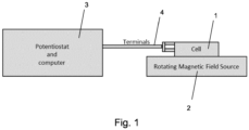
- the arrangement of equipment shown in Figure 1 can be used to enhance and monitor the performance of a cell 1 while charging or discharging.
- the cell 1 is located on top of a rotating magnetic field generator 2.
- the cell 1 is connected to the potentiostat and computer 3 via terminals 4.
- the potentiostat controls the potential across the cell 1 and may charge or discharge the cell 1.
- the computer monitors the current, and/or capacity and/or voltage of the cell 1.
- the rotating magnetic field generator 2 provides a rotating magnetic field through the cell 1.
- This arrangement can be used for testing the cell, but when monitoring of the cell 1 is not required, the potentiostat, computer 3 and terminals 4 can be removed and optionally replaced by a power source or drain for charging or discharging the cell.
- the cell 1 is located on top of the rotating magnetic field generator 2, but in other embodiments of the invention, the cell 1 and rotating magnetic field generator 2 may be oriented differently as long as the rotating magnetic field generator 2 can produce a magnetic field through the cell 1.
- the rotation of the magnetic field may be around an axis substantially parallel to the direction of the magnetic field produced.
- the direction of the magnetic field produced in the cell 1 may be substantially parallel to a direction between the magnetic field generator 2 and the cell 1 and the rotation of the field may be around an axis parallel to a direction between the magnetic field generator 2 and the cell 1 as shown in Figures 2A and 2B .
- the rotation magnetic field may be around an axis substantially perpendicular to the direction of the magnetic field produced.
- the direction of the magnetic field produced in the cell 1 may be substantially perpendicular to a direction between the magnetic field generator 2 and the cell 1 and the rotation of the field may be around an axis parallel to a direction between the magnetic field generator 2 and the cell 1.
- the rotating magnetic field generator 2 in the arrangement of Figure 1 may be replaced with a changing magnetic field generator that produces a changing magnetic field that varies in another way.
- a changing magnetic field generator may be used in to produce a magnetic field that rotates and/or oscillates and/or pulses.
- the term "under field conditions" refers to the presence of a changing magnetic field.
- results for charging the cells in the presence of a changing magnetic field are shown along with comparative examples of the cells in the absence of a changing magnetic field.
- the arrangements used in the examples and in the comparative examples differ only in that the magnetic field provided in the comparative examples is constant in direction and magnitude, whereas the magnetic field provided in the examples is changing.
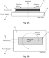
- Figure 2 shows an arrangement used to enhance performance of a pouch cell 11.
- the magnetic field generator 12 produces a magnetic field having a direction parallel to the direction shown by the arrow in Figure 2A .
- the magnetic field produced rotates in the direction shown by the arrow in Figure 2B .
- the magnetic field passes through pouch cell 11.
- the magnetic field may be offset from the axis of rotation to ensure that the magnetic flux in the cell changes over time.
- the magnetic field generator 12 is an electromagnet powered by power supply 15. Potentiostat 13 is connected to the pouch cell 11 and controls the potential over the cell and can be used to charge or discharge the cell.
- the pouch cell 11 is formed of a first electrode and a second electrode separated from one another by an electrolyte.
- the electrodes are substantially parallel and extend across a length and width of the cell.
- the pouch cell 11 has contacts for each of the electrodes which may be connected to a potentiostat as shown in Figure 2 .
- the pouch cell 11 is oriented so that the direction of the magnetic field passes through the first electrode of the cell, through the electrolyte and through the second electrode.
- the direction of the magnetic field is parallel to the direction of a current path between the electrodes.
- the rotation plane of the magnetic field is parallel to the planes of the electrodes.
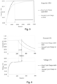
- Figure 3 shows the capacity of pouch cell 11 when charged in the presence of a magnetic field produced by the magnetic field generator 12 when the field is (i) rotating (shown by the dashed line) and (ii) not rotating (shown by the solid line).
- the pouch cell 11 was charged in two phases. In the first phase, the cell was charged from 3.4V to 4.2V at 0.841A until 4.2V was reached and then in the second phase, the cell was held at constant voltage while the current decayed and capacity was reached.
- the first phase where a constant current is applied to the cell can be seen by the horizontal line portions of the current graph in Figure 4 .
- the second phase where voltage is held constant and current decays while full capacity is reached can be seen where the current changes.
- the straight horizontal lines to t 220 and 300 seconds for no changing field and changing field respectively, represent the constant current portion of the charging and t onwards representing the constant voltage portion of the charging.
- a magnetic field was produced by an electromagnet in the magnetic field generator 12. During the cycle shown by the dashed line, the electromagnet was spun at 1160 rpm. The results show that the time taken to charge the cell was reduced by 68% by the presence of the rotating magnetic field.
- Figure 4 shows the current and voltage during the charging of the pouch cell 11 in the conditions described in relation to Figure 3 .
- the dashed line shows the charge when the magnetic field is rotating and the solid line shows charging when the magnetic field is not rotating (it is constant).
- the graphs show that, in the presence of a rotating magnetic field, the time taken to reach the voltage of 4.2V is increased so that the first phase of charging where current is applied is maintained for a longer period. As the first phase of charging increases the charge held by the cell more quickly than the second phase, this means that charging overall is quicker when the rotating magnetic field is present through the cell.
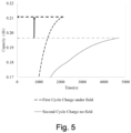
- Figure 5 shows the capacity of the pouch cell 11 when charged in the presence of a magnetic field produced by magnetic field generator 12 when the field is (i) rotating (shown by the dashed line) and (ii) not rotating (shown by the solid line).
- the pouch cell 11 was charged in two phases. In the first phase, the cell was charged from 3.4V to 4.2V at 0.841A until 4.2V was reached and then in the second phase, the cell was held at constant voltage while the current decayed and capacity was reached.
- Figure 6 shows results of testing a pouch cell 21.
- the pouch cell 21 has a 400mAh capacity and has dimensions of 5cm by 2cm by 0.5cm.
- the pouch cell 21 is commercially available via the part information: +PL-402248-2C, 3.7V 400mAh -PO 7006 20140726.
- the rate of charge of the pouch cell 21 is shown in Figure 6 for nine charge cycles. Cycles 1 to 3, 7 and 8 were in the presence of a magnetic field rotating at 1170 rpm and cycle 9 was in the presence of the magnetic field rotating at 1000 rpm. Cycles 4 to 6 were in the presence of a static magnetic field.
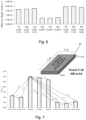
- Figure 7 shows the time taken to charge pouch cell 21 in eight charge cycles with a rotating field at 1170 rpm, a rotating field at 1000 rpm, and a static magnetic field (labelled 'no field' in the figure). As can be seen in Figure 7 , the time taken to charge the cell is consistently decreased by around 15% in the presence of a rotating magnetic field.
- Figure 8 shows results of testing a pouch cell 31.
- the pouch cell 31 has a 200mAh capacity and has dimensions of 2.5cm by 1.7cm by 0.5cm.
- the pouch cell 31 is commercially available via the part information: -PL-651628-2C, 3.7V 210mAh +PO 7994.
- the rate of charge of the pouch cell 31 is shown in Figure 8 for two charge cycles.
- the first cycle was in the presence of a magnetic field rotating at 1160 rpm and the second cycle was in the presence of a static magnetic field.
- Figure 9 shows the time taken to charge pouch cell 31 in a charge cycle with a rotating field at 1160 rpm, and a static magnetic field (labelled 'no field' in the figure). As can be seen in Figure 9 , the time taken to charge the cell at 4C is decreased by 58% in the presence of a rotating magnetic field.
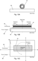
- FIG 10 shows an arrangement used to enhance performance of a Swagelok-type cell 41.
- the magnetic field generator 42 produces a magnetic field having the direction parallel to the direction shown by the arrow in Figure 10A .
- the magnetic field produced rotates in the direction shown by the arrow in Figure 10B .
- the magnetic field passes through Swagelok cell 41.
- the magnetic field may be offset from the axis of rotation to ensure that the magnetic flux in the cell changes over time.
- the magnetic field generator 42 is an electromagnet powered by power supply 45.
- Potentiostat 43 is connected to the Swagelok cell 41 and controls the potential over the cell and can be used to charge the cell.
- the Swagelok cell 41 is formed of a first electrode and a second electrode separated from one another by an electrolyte and separator material.
- the electrodes are substantially parallel and extend across a length and width of the cell.
- the Swagelok cell 41 has contacts for each of the electrodes which may be connected to a potentiostat as shown in Figure 10 .
- the Swagelok cell 41 is oriented so that the direction of the magnetic field passes through the cell, perpendicularly to the direction of a current path between the electrodes.
- the rotation plane of the magnetic field is perpendicular to the planes of the electrodes.
- FIG 11 shows results of testing Swagelok cell 51.
- the Swagelok cell 51 has dimensions of 5cm by 2.5cm.
- the Swagelok cell 51 is commercially available as a LMO/Graphite Swagelok cell.
- the rate of charge of the Swagelok cell 51 is shown in Figure 11 for charge cycles at 1C, 2C and 3C, each in the presence of a rotating magnetic field and in the presence of a static magnetic field (labelled as no field in the figure).
- the rotating magnetic field had a speed of 1100 rpm.
- Figure 12 shows the time taken to charge Swagelok cell 51 in charge cycles at 1C, 2C and 3C, each in the presence of a rotating magnetic field and in the presence of a static magnetic field (labelled as no field in the figure). As can be seen in Figure 12 , the time taken to charge the cell 51 is consistently decreased in the presence of a rotating magnetic field.
- Figure 13 shows an arrangement used to enhance performance of a cylindrical cell 61.
- the magnetic field generator 62 produces a magnetic field having the direction parallel to the direction shown by the arrow in Figure 13B .
- the magnetic field produced rotates in the direction shown by the arrow in Figure 13C .
- the magnetic field passes through cylindrical cell 61.
- the cylindrical cell 61 is formed of a first electrode and a second electrode separated from one another by an electrolyte.
- the electrodes are rolled into a spiral configuration and extend across a length of the cell.
- the cylindrical cell 61 has contacts for each of the electrodes which may be connected to a potentiostat as shown in Figure 13 .
- the cylindrical cell 61 is oriented in Figure 13 so that the direction of the magnetic field passes through the cross-section of the cylindrical shape, perpendicularly to a direction between the flat ends of the cylindrical shape.
- the rotation plane of the magnetic field is perpendicular to the planes of the end faces of the cylindrical cell.
- the cylindrical cell may alternatively be oriented so that the direction of the magnetic field passes through the ends of the cylindrical cell.
- the magnetic field be offset from the axis of rotation to ensure that the magnetic flux in the cell changes over time.
- the magnetic field generator 62 is an electromagnet powered by power supply 65.
- Potentiostat 63 is connected to the cylindrical cell 61 and controls the potential over the cell and can be used to charge the cell.
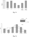
- Figure 14 shows results of testing cylindrical cell 71.
- the cylindrical cell 71 has dimensions of 6.5cm by 1.8cm.
- the cylindrical cell 51 is commercially available as a cylindrical 2190 mAh LG 18650 cell.
- the rate of charge of the cylindrical cell 71 is shown in Figure 14 for six charge cycles. Cycles 1 and 2 were in the presence of a magnetic field rotating at 1170 rpm, cycle 5 was in the presence of the magnetic field rotating at 1500 rpm and cycle 6 was in the presence of a magnetic field rotating at 1200 rpm. Cycles 3 and 4 were in the presence of a static magnetic field. In cycles 5 and 6, the cylindrical cell was positioned so at an orientation 90 degrees from the position shown in Figure 13A so that a flat end of the cell faces the magnetic field generator 62.
- the rate of charging was generally higher in the presence of a rotating magnetic field.
- Figure 15 shows the time taken to charge cylindrical cell 71 in the charge cycles of Figure 14 . As can be seen in Figure 15 , the time taken to charge the cell 71 was generally lower in the presence of a rotating magnetic field.
- the ion velocity, v within a liquid electrolyte will increase until overcome by drag forces, F D .
- the electric field force, F E which drives the motion of the ion can be described by:
- the drag force can be approximated from Stoke's law as:
- Equating the electric and drag forces determines the terminal velocity of the ion, thus mobility, u i :
- the mobility influences the conductivity through the equation:
- the Ohmic resistance, ⁇ can be described by:
- the magnetic field influences the activation energy as:
- the magnetic field can be produced using a permanent magnet or an electromagnet.
Landscapes
- Engineering & Computer Science (AREA)
- Manufacturing & Machinery (AREA)
- Chemical & Material Sciences (AREA)
- Chemical Kinetics & Catalysis (AREA)
- Electrochemistry (AREA)
- General Chemical & Material Sciences (AREA)
- Power Engineering (AREA)
- Secondary Cells (AREA)
- Charge And Discharge Circuits For Batteries Or The Like (AREA)
- Hybrid Cells (AREA)
- Fuel Cell (AREA)
Priority Applications (1)
| Application Number | Priority Date | Filing Date | Title |
|---|---|---|---|
| EP25154539.8A EP4593154A1 (de) | 2019-01-07 | 2020-01-06 | Verfahren zur leistungsverbesserung elektrochemischer zellen |
Applications Claiming Priority (3)
| Application Number | Priority Date | Filing Date | Title |
|---|---|---|---|
| GB201900171 | 2019-01-07 | ||
| EP20700245.2A EP3909092B1 (de) | 2019-01-07 | 2020-01-06 | Verfahren zur verbesserung der leistung elektrochemischer zellen |
| PCT/EP2020/050145 WO2020144142A1 (en) | 2019-01-07 | 2020-01-06 | Method of enhancing electrochemical cell performance |
Related Parent Applications (2)
| Application Number | Title | Priority Date | Filing Date |
|---|---|---|---|
| EP20700245.2A Division EP3909092B1 (de) | 2019-01-07 | 2020-01-06 | Verfahren zur verbesserung der leistung elektrochemischer zellen |
| EP20700245.2A Division-Into EP3909092B1 (de) | 2019-01-07 | 2020-01-06 | Verfahren zur verbesserung der leistung elektrochemischer zellen |
Related Child Applications (2)
| Application Number | Title | Priority Date | Filing Date |
|---|---|---|---|
| EP25154539.8A Division-Into EP4593154A1 (de) | 2019-01-07 | 2020-01-06 | Verfahren zur leistungsverbesserung elektrochemischer zellen |
| EP25154539.8A Division EP4593154A1 (de) | 2019-01-07 | 2020-01-06 | Verfahren zur leistungsverbesserung elektrochemischer zellen |
Publications (3)
| Publication Number | Publication Date |
|---|---|
| EP4167343A1 true EP4167343A1 (de) | 2023-04-19 |
| EP4167343B1 EP4167343B1 (de) | 2025-03-12 |
| EP4167343C0 EP4167343C0 (de) | 2025-03-12 |
Family
ID=69147700
Family Applications (3)
| Application Number | Title | Priority Date | Filing Date |
|---|---|---|---|
| EP25154539.8A Pending EP4593154A1 (de) | 2019-01-07 | 2020-01-06 | Verfahren zur leistungsverbesserung elektrochemischer zellen |
| EP20700245.2A Active EP3909092B1 (de) | 2019-01-07 | 2020-01-06 | Verfahren zur verbesserung der leistung elektrochemischer zellen |
| EP22211233.6A Active EP4167343B1 (de) | 2019-01-07 | 2020-01-06 | Verfahren zur leistungsverbesserung elektrochemischer zellen |
Family Applications Before (2)
| Application Number | Title | Priority Date | Filing Date |
|---|---|---|---|
| EP25154539.8A Pending EP4593154A1 (de) | 2019-01-07 | 2020-01-06 | Verfahren zur leistungsverbesserung elektrochemischer zellen |
| EP20700245.2A Active EP3909092B1 (de) | 2019-01-07 | 2020-01-06 | Verfahren zur verbesserung der leistung elektrochemischer zellen |
Country Status (8)
| Country | Link |
|---|---|
| US (2) | US12068463B2 (de) |
| EP (3) | EP4593154A1 (de) |
| JP (3) | JP7399170B2 (de) |
| KR (2) | KR20250154510A (de) |
| CN (2) | CN119230991A (de) |
| ES (1) | ES2980369T3 (de) |
| PL (1) | PL3909092T3 (de) |
| WO (1) | WO2020144142A1 (de) |
Families Citing this family (9)
| Publication number | Priority date | Publication date | Assignee | Title |
|---|---|---|---|---|
| US12068463B2 (en) * | 2019-01-07 | 2024-08-20 | UCL business Limited | Method of enhancing electrochemical cell performance |
| DE102023200003A1 (de) * | 2023-01-02 | 2024-07-04 | Volkswagen Aktiengesellschaft | Lithium-Ionen-Batteriezelle |
| GB2617438B (en) * | 2023-01-27 | 2024-05-01 | Gaussion Ltd | Magnetic flux generator |
| GB2628591B (en) * | 2023-03-29 | 2025-06-11 | Gaussion Ltd | Apparatus for use with electrochemical cells |
| GB2628585B (en) * | 2023-03-29 | 2025-06-04 | Gaussion Ltd | Magnetic flux generator |
| DE102023203762B3 (de) | 2023-04-24 | 2024-10-24 | Volkswagen Aktiengesellschaft | Lithium-Ionen-Batteriezelle |
| US20240396096A1 (en) * | 2023-05-26 | 2024-11-28 | Arthur Oded Ruppin | Electromagnetic stimulated rechargeable battery |
| US20250070272A1 (en) * | 2023-08-25 | 2025-02-27 | Arthur Oded Ruppin | Rechargeable battery with rotating electrode |
| WO2026038538A1 (ja) * | 2024-08-14 | 2026-02-19 | 茂 平峰 | 電池の性能向上方法 |
Citations (3)
| Publication number | Priority date | Publication date | Assignee | Title |
|---|---|---|---|---|
| US20040200731A1 (en) * | 2003-04-11 | 2004-10-14 | Sullivan John Timothy | Apparatus and method for generating and using multi-direction DC and AC electrical currents |
| US20100159293A1 (en) * | 2008-06-24 | 2010-06-24 | Imp Gmbh | Device for producing electrical energy and a charging current signal, and a device for producing electrical energy charged by the charging current signal |
| EP3033796A1 (de) * | 2013-08-15 | 2016-06-22 | Robert Bosch GmbH | Hybride ionische elektronische energiespeichervorrichtung |
Family Cites Families (19)
| Publication number | Priority date | Publication date | Assignee | Title |
|---|---|---|---|---|
| JPH0684544A (ja) * | 1992-09-01 | 1994-03-25 | Nippondenso Co Ltd | リチウム二次電池 |
| US5817221A (en) * | 1994-08-25 | 1998-10-06 | University Of Iowa Research Foundation | Composites formed using magnetizable material, a catalyst and an electron conductor |
| US5871625A (en) * | 1994-08-25 | 1999-02-16 | University Of Iowa Research Foundation | Magnetic composites for improved electrolysis |
| JPH09306489A (ja) * | 1996-05-14 | 1997-11-28 | Sony Corp | 非水電解液二次電池用負極材料とこの非水電解液二次電池用負極材料の製造方法およびこれを用いた非水電解液二次電池 |
| JP2000315505A (ja) * | 1999-04-30 | 2000-11-14 | Ntt Data Corp | 一次電池、二次電池、二次電池の充電装置、二次電池への充電方法 |
| GB0210886D0 (en) * | 2002-05-13 | 2002-06-19 | Zap Wireless Technologies Ltd | Improvements relating to contact-less power transfer |
| US8928276B2 (en) * | 2008-09-27 | 2015-01-06 | Witricity Corporation | Integrated repeaters for cell phone applications |
| JP5601550B2 (ja) * | 2011-02-18 | 2014-10-08 | トヨタ自動車株式会社 | リチウムイオン二次電池とその製造方法 |
| CN102832421A (zh) * | 2012-09-11 | 2012-12-19 | 胡小华 | 电池磁催化方法 |
| EP2793300A1 (de) * | 2013-04-16 | 2014-10-22 | ETH Zurich | Verfahren zur Herstellung von Elektroden und mit einem solchen Verfahren hergestellte Elektroden |
| DE102013112555B3 (de) * | 2013-11-14 | 2014-11-06 | Helmholtz-Zentrum Dresden - Rossendorf E.V. | Energiespeicheranordnung, deren Verwendung und Energiespeicherzellenanordnung |
| CN104241675B (zh) * | 2014-08-29 | 2017-01-18 | 孙旭阳 | 一种磁控金属二次电池 |
| WO2016029418A1 (zh) * | 2014-08-29 | 2016-03-03 | 孙旭阳 | 一种磁控金属二次电池 |
| JP6542599B2 (ja) * | 2015-07-02 | 2019-07-10 | 古河電気工業株式会社 | 鉛蓄電池管理装置および鉛蓄電池管理方法 |
| CN106026231B (zh) * | 2016-05-30 | 2019-12-10 | Oppo广东移动通信有限公司 | 一种无线充电方法及装置 |
| EP3485068B1 (de) * | 2016-07-13 | 2026-04-08 | Iontra Inc | Elektrochemische verfahren, vorrichtungen und zusammensetzungen |
| CN107204490B (zh) * | 2017-04-17 | 2019-04-26 | 超威电源有限公司 | 一种动力型铅蓄电池磁力内化成方法 |
| CN106972213B (zh) * | 2017-05-09 | 2019-01-11 | 超威电源有限公司 | 一种铅酸蓄电池的容量快速恢复方法 |
| US12068463B2 (en) * | 2019-01-07 | 2024-08-20 | UCL business Limited | Method of enhancing electrochemical cell performance |
-
2020
- 2020-01-06 US US17/420,832 patent/US12068463B2/en active Active
- 2020-01-06 EP EP25154539.8A patent/EP4593154A1/de active Pending
- 2020-01-06 EP EP20700245.2A patent/EP3909092B1/de active Active
- 2020-01-06 KR KR1020257033152A patent/KR20250154510A/ko active Pending
- 2020-01-06 WO PCT/EP2020/050145 patent/WO2020144142A1/en not_active Ceased
- 2020-01-06 ES ES20700245T patent/ES2980369T3/es active Active
- 2020-01-06 KR KR1020217023498A patent/KR102869687B1/ko active Active
- 2020-01-06 JP JP2021538312A patent/JP7399170B2/ja active Active
- 2020-01-06 CN CN202411277673.1A patent/CN119230991A/zh active Pending
- 2020-01-06 PL PL20700245.2T patent/PL3909092T3/pl unknown
- 2020-01-06 CN CN202080008389.8A patent/CN113302779B/zh active Active
- 2020-01-06 EP EP22211233.6A patent/EP4167343B1/de active Active
-
2023
- 2023-12-05 JP JP2023205665A patent/JP7576146B2/ja active Active
-
2024
- 2024-07-17 US US18/776,015 patent/US20240372162A1/en active Pending
- 2024-10-18 JP JP2024184174A patent/JP7739569B2/ja active Active
Patent Citations (3)
| Publication number | Priority date | Publication date | Assignee | Title |
|---|---|---|---|---|
| US20040200731A1 (en) * | 2003-04-11 | 2004-10-14 | Sullivan John Timothy | Apparatus and method for generating and using multi-direction DC and AC electrical currents |
| US20100159293A1 (en) * | 2008-06-24 | 2010-06-24 | Imp Gmbh | Device for producing electrical energy and a charging current signal, and a device for producing electrical energy charged by the charging current signal |
| EP3033796A1 (de) * | 2013-08-15 | 2016-06-22 | Robert Bosch GmbH | Hybride ionische elektronische energiespeichervorrichtung |
Also Published As
| Publication number | Publication date |
|---|---|
| EP3909092C0 (de) | 2024-04-03 |
| JP2025020174A (ja) | 2025-02-12 |
| JP2024037796A (ja) | 2024-03-19 |
| US20240372162A1 (en) | 2024-11-07 |
| KR20250154510A (ko) | 2025-10-28 |
| JP7739569B2 (ja) | 2025-09-16 |
| CN113302779A (zh) | 2021-08-24 |
| JP2022515678A (ja) | 2022-02-21 |
| US12068463B2 (en) | 2024-08-20 |
| CN119230991A (zh) | 2024-12-31 |
| US20220093981A1 (en) | 2022-03-24 |
| ES2980369T3 (es) | 2024-10-01 |
| EP3909092A1 (de) | 2021-11-17 |
| WO2020144142A1 (en) | 2020-07-16 |
| PL3909092T3 (pl) | 2024-07-29 |
| EP4167343B1 (de) | 2025-03-12 |
| EP4167343C0 (de) | 2025-03-12 |
| JP7576146B2 (ja) | 2024-10-30 |
| EP3909092B1 (de) | 2024-04-03 |
| JP7399170B2 (ja) | 2023-12-15 |
| EP4593154A1 (de) | 2025-07-30 |
| CN113302779B (zh) | 2024-10-01 |
| KR102869687B1 (ko) | 2025-10-14 |
| KR20210110635A (ko) | 2021-09-08 |
Similar Documents
| Publication | Publication Date | Title |
|---|---|---|
| EP3909092B1 (de) | Verfahren zur verbesserung der leistung elektrochemischer zellen | |
| EP3033796B1 (de) | Hybride ionische elektronische energiespeichervorrichtung | |
| Shen et al. | Charging algorithms of lithium-ion batteries: An overview | |
| KR102169774B1 (ko) | 리튬-이온 배터리 시스템의 개개의 전극들의 용량 및 총 용량을 추정하기 위한 방법 및 시스템 | |
| KR102441469B1 (ko) | 배터리 충전 방법 및 배터리 충전 장치 | |
| CN110161417A (zh) | 一种基于三电极体系的锂离子电池析锂量化分析方法 | |
| EP1042827A1 (de) | Batterie und verfahren zur herstellung | |
| CN107980099A (zh) | 确定在电池组电池中阳极的电势和/或阴极的电势的方法 | |
| JP6035900B2 (ja) | 全固体リチウムイオン二次電池 | |
| CN112072196A (zh) | 锂离子电池快速充电方法及装置 | |
| Danilov et al. | Adaptive battery management systems for the new generation of electrical vehicles | |
| HK40092191B (en) | Method of enhancing electrochemical cell performance | |
| HK40092191A (en) | Method of enhancing electrochemical cell performance | |
| US11332844B2 (en) | Battery-powered electroplating barrel and methods of use | |
| CN109391008B (zh) | 一种具有防止过充的手机锂电池 | |
| CN110676527B (zh) | 一种去除锂电池充放电毛刺的装置及电池 | |
| US20240396096A1 (en) | Electromagnetic stimulated rechargeable battery | |
| Lall et al. | Flex-to-Install Application Performance of Power Sources Subjected to Varying Fold Orientations, C-Rates and Depths of Charge | |
| US20250070272A1 (en) | Rechargeable battery with rotating electrode | |
| JPH0371566A (ja) | ポリマー電解質二次電池の充電方法 | |
| Gunasekar et al. | Lithium–Ion Battery Degradation and Estimation of Battery Parameters | |
| Sandeep et al. | Charging algorithms of lithium-ion batteries: an overview | |
| CN115642325A (zh) | 电池充电方法及电路、多电芯电池、终端设备与电子设备 | |
| KR20240174322A (ko) | 배터리 관리 시스템 및 배터리 관리 방법 |
Legal Events
| Date | Code | Title | Description |
|---|---|---|---|
| PUAI | Public reference made under article 153(3) epc to a published international application that has entered the european phase |
Free format text: ORIGINAL CODE: 0009012 |
|
| STAA | Information on the status of an ep patent application or granted ep patent |
Free format text: STATUS: THE APPLICATION HAS BEEN PUBLISHED |
|
| STAA | Information on the status of an ep patent application or granted ep patent |
Free format text: STATUS: REQUEST FOR EXAMINATION WAS MADE |
|
| AC | Divisional application: reference to earlier application |
Ref document number: 3909092 Country of ref document: EP Kind code of ref document: P |
|
| AK | Designated contracting states |
Kind code of ref document: A1 Designated state(s): AL AT BE BG CH CY CZ DE DK EE ES FI FR GB GR HR HU IE IS IT LI LT LU LV MC MK MT NL NO PL PT RO RS SE SI SK SM TR |
|
| 17P | Request for examination filed |
Effective date: 20230330 |
|
| RBV | Designated contracting states (corrected) |
Designated state(s): AL AT BE BG CH CY CZ DE DK EE ES FI FR GB GR HR HU IE IS IT LI LT LU LV MC MK MT NL NO PL PT RO RS SE SI SK SM TR |
|
| STAA | Information on the status of an ep patent application or granted ep patent |
Free format text: STATUS: EXAMINATION IS IN PROGRESS |
|
| 17Q | First examination report despatched |
Effective date: 20230801 |
|
| REG | Reference to a national code |
Ref country code: HK Ref legal event code: DE Ref document number: 40092191 Country of ref document: HK |
|
| GRAP | Despatch of communication of intention to grant a patent |
Free format text: ORIGINAL CODE: EPIDOSNIGR1 |
|
| STAA | Information on the status of an ep patent application or granted ep patent |
Free format text: STATUS: GRANT OF PATENT IS INTENDED |
|
| INTG | Intention to grant announced |
Effective date: 20240429 |
|
| RIN1 | Information on inventor provided before grant (corrected) |
Inventor name: TAN, CHUN Inventor name: BRETT, DANIEL Inventor name: SHEARING, PAUL Inventor name: HEENAN, THOMAS |
|
| GRAJ | Information related to disapproval of communication of intention to grant by the applicant or resumption of examination proceedings by the epo deleted |
Free format text: ORIGINAL CODE: EPIDOSDIGR1 |
|
| STAA | Information on the status of an ep patent application or granted ep patent |
Free format text: STATUS: EXAMINATION IS IN PROGRESS |
|
| GRAP | Despatch of communication of intention to grant a patent |
Free format text: ORIGINAL CODE: EPIDOSNIGR1 |
|
| STAA | Information on the status of an ep patent application or granted ep patent |
Free format text: STATUS: GRANT OF PATENT IS INTENDED |
|
| INTC | Intention to grant announced (deleted) | ||
| INTG | Intention to grant announced |
Effective date: 20241001 |
|
| GRAS | Grant fee paid |
Free format text: ORIGINAL CODE: EPIDOSNIGR3 |
|
| GRAA | (expected) grant |
Free format text: ORIGINAL CODE: 0009210 |
|
| STAA | Information on the status of an ep patent application or granted ep patent |
Free format text: STATUS: THE PATENT HAS BEEN GRANTED |
|
| AC | Divisional application: reference to earlier application |
Ref document number: 3909092 Country of ref document: EP Kind code of ref document: P |
|
| AK | Designated contracting states |
Kind code of ref document: B1 Designated state(s): AL AT BE BG CH CY CZ DE DK EE ES FI FR GB GR HR HU IE IS IT LI LT LU LV MC MK MT NL NO PL PT RO RS SE SI SK SM TR |
|
| REG | Reference to a national code |
Ref country code: GB Ref legal event code: FG4D |
|
| REG | Reference to a national code |
Ref country code: CH Ref legal event code: EP |
|
| REG | Reference to a national code |
Ref country code: DE Ref legal event code: R096 Ref document number: 602020047796 Country of ref document: DE |
|
| REG | Reference to a national code |
Ref country code: IE Ref legal event code: FG4D |
|
| U01 | Request for unitary effect filed |
Effective date: 20250320 |
|
| U07 | Unitary effect registered |
Designated state(s): AT BE BG DE DK EE FI FR IT LT LU LV MT NL PT RO SE SI Effective date: 20250326 |
|
| PG25 | Lapsed in a contracting state [announced via postgrant information from national office to epo] |
Ref country code: RS Free format text: LAPSE BECAUSE OF FAILURE TO SUBMIT A TRANSLATION OF THE DESCRIPTION OR TO PAY THE FEE WITHIN THE PRESCRIBED TIME-LIMIT Effective date: 20250612 |
|
| PG25 | Lapsed in a contracting state [announced via postgrant information from national office to epo] |
Ref country code: ES Free format text: LAPSE BECAUSE OF FAILURE TO SUBMIT A TRANSLATION OF THE DESCRIPTION OR TO PAY THE FEE WITHIN THE PRESCRIBED TIME-LIMIT Effective date: 20250312 |
|
| PG25 | Lapsed in a contracting state [announced via postgrant information from national office to epo] |
Ref country code: NO Free format text: LAPSE BECAUSE OF FAILURE TO SUBMIT A TRANSLATION OF THE DESCRIPTION OR TO PAY THE FEE WITHIN THE PRESCRIBED TIME-LIMIT Effective date: 20250612 |
|
| PG25 | Lapsed in a contracting state [announced via postgrant information from national office to epo] |
Ref country code: HR Free format text: LAPSE BECAUSE OF FAILURE TO SUBMIT A TRANSLATION OF THE DESCRIPTION OR TO PAY THE FEE WITHIN THE PRESCRIBED TIME-LIMIT Effective date: 20250312 |
|
| PG25 | Lapsed in a contracting state [announced via postgrant information from national office to epo] |
Ref country code: GR Free format text: LAPSE BECAUSE OF FAILURE TO SUBMIT A TRANSLATION OF THE DESCRIPTION OR TO PAY THE FEE WITHIN THE PRESCRIBED TIME-LIMIT Effective date: 20250613 |
|
| PG25 | Lapsed in a contracting state [announced via postgrant information from national office to epo] |
Ref country code: SM Free format text: LAPSE BECAUSE OF FAILURE TO SUBMIT A TRANSLATION OF THE DESCRIPTION OR TO PAY THE FEE WITHIN THE PRESCRIBED TIME-LIMIT Effective date: 20250312 |
|
| PG25 | Lapsed in a contracting state [announced via postgrant information from national office to epo] |
Ref country code: PL Free format text: LAPSE BECAUSE OF FAILURE TO SUBMIT A TRANSLATION OF THE DESCRIPTION OR TO PAY THE FEE WITHIN THE PRESCRIBED TIME-LIMIT Effective date: 20250312 |
|
| PG25 | Lapsed in a contracting state [announced via postgrant information from national office to epo] |
Ref country code: CZ Free format text: LAPSE BECAUSE OF FAILURE TO SUBMIT A TRANSLATION OF THE DESCRIPTION OR TO PAY THE FEE WITHIN THE PRESCRIBED TIME-LIMIT Effective date: 20250312 |
|
| PG25 | Lapsed in a contracting state [announced via postgrant information from national office to epo] |
Ref country code: SK Free format text: LAPSE BECAUSE OF FAILURE TO SUBMIT A TRANSLATION OF THE DESCRIPTION OR TO PAY THE FEE WITHIN THE PRESCRIBED TIME-LIMIT Effective date: 20250312 |
|
| PG25 | Lapsed in a contracting state [announced via postgrant information from national office to epo] |
Ref country code: IS Free format text: LAPSE BECAUSE OF FAILURE TO SUBMIT A TRANSLATION OF THE DESCRIPTION OR TO PAY THE FEE WITHIN THE PRESCRIBED TIME-LIMIT Effective date: 20250712 |
|
| PLBE | No opposition filed within time limit |
Free format text: ORIGINAL CODE: 0009261 |
|
| STAA | Information on the status of an ep patent application or granted ep patent |
Free format text: STATUS: NO OPPOSITION FILED WITHIN TIME LIMIT |
|
| REG | Reference to a national code |
Ref country code: CH Ref legal event code: L10 Free format text: ST27 STATUS EVENT CODE: U-0-0-L10-L00 (AS PROVIDED BY THE NATIONAL OFFICE) Effective date: 20260121 |
|
| 26N | No opposition filed |
Effective date: 20251215 |
|
| U20 | Renewal fee for the european patent with unitary effect paid |
Year of fee payment: 7 Effective date: 20260119 |
|
| PGFP | Annual fee paid to national office [announced via postgrant information from national office to epo] |
Ref country code: GB Payment date: 20260119 Year of fee payment: 7 |