EP4167378A1 - Isolierte hochfrequenzantennenanordnung - Google Patents
Isolierte hochfrequenzantennenanordnung Download PDFInfo
- Publication number
- EP4167378A1 EP4167378A1 EP22200222.2A EP22200222A EP4167378A1 EP 4167378 A1 EP4167378 A1 EP 4167378A1 EP 22200222 A EP22200222 A EP 22200222A EP 4167378 A1 EP4167378 A1 EP 4167378A1
- Authority
- EP
- European Patent Office
- Prior art keywords
- antenna
- insulator
- branch
- frequency
- frequency band
- Prior art date
- Legal status (The legal status is an assumption and is not a legal conclusion. Google has not performed a legal analysis and makes no representation as to the accuracy of the status listed.)
- Granted
Links
Images





Classifications
-
- H—ELECTRICITY
- H01—ELECTRIC ELEMENTS
- H01Q—ANTENNAS, i.e. RADIO AERIALS
- H01Q1/00—Details of, or arrangements associated with, antennas
- H01Q1/52—Means for reducing coupling between antennas; Means for reducing coupling between an antenna and another structure
- H01Q1/521—Means for reducing coupling between antennas; Means for reducing coupling between an antenna and another structure reducing the coupling between adjacent antennas
-
- H—ELECTRICITY
- H01—ELECTRIC ELEMENTS
- H01Q—ANTENNAS, i.e. RADIO AERIALS
- H01Q21/00—Antenna arrays or systems
- H01Q21/28—Combinations of substantially independent non-interacting antenna units or systems
-
- H—ELECTRICITY
- H01—ELECTRIC ELEMENTS
- H01Q—ANTENNAS, i.e. RADIO AERIALS
- H01Q19/00—Combinations of primary active antenna elements and units with secondary devices, e.g. with quasi-optical devices, for giving the antenna a desired directional characteristic
- H01Q19/02—Details
- H01Q19/021—Means for reducing undesirable effects
-
- H—ELECTRICITY
- H01—ELECTRIC ELEMENTS
- H01Q—ANTENNAS, i.e. RADIO AERIALS
- H01Q21/00—Antenna arrays or systems
- H01Q21/06—Arrays of individually energised antenna units similarly polarised and spaced apart
- H01Q21/20—Arrays of individually energised antenna units similarly polarised and spaced apart the units being spaced along or adjacent to a curvilinear path
-
- H—ELECTRICITY
- H01—ELECTRIC ELEMENTS
- H01Q—ANTENNAS, i.e. RADIO AERIALS
- H01Q5/00—Arrangements for simultaneous operation of antennas on two or more different wavebands, e.g. dual-band or multi-band arrangements
- H01Q5/30—Arrangements for providing operation on different wavebands
- H01Q5/307—Individual or coupled radiating elements, each element being fed in an unspecified way
-
- H—ELECTRICITY
- H01—ELECTRIC ELEMENTS
- H01Q—ANTENNAS, i.e. RADIO AERIALS
- H01Q9/00—Electrically-short antennas having dimensions not more than twice the operating wavelength and consisting of conductive active radiating elements
- H01Q9/04—Resonant antennas
- H01Q9/16—Resonant antennas with feed intermediate between the extremities of the antenna, e.g. centre-fed dipole
- H01Q9/28—Conical, cylindrical, cage, strip, gauze, or like elements having an extended radiating surface; Elements comprising two conical surfaces having collinear axes and adjacent apices and fed by two-conductor transmission lines
- H01Q9/285—Planar dipole
Definitions
- the invention relates to the field of radio frequency devices comprising a plurality of antennas.
- the invention applies in particular when the antennas operate in adjacent or even similar frequency bands.
- Some recent electrical equipment for example residential gateways , comprise a plurality of antennas in order to transmit and receive radio frequency signals in different frequency bands.
- To limit interference between the antennas it is necessary to ensure that said antennas are properly isolated from each other. This is particularly critical when the frequency bands used in the same equipment are adjacent (for example 5GHz Wi-Fi and 6GHz Wi-Fi), or even similar.
- Diversity techniques are also known, for example spatial diversity, polarization diversity or radiation diversity. Nevertheless, the performances of these techniques are generally limited when they are implemented in a compact equipment. In particular, they do not make it possible to ensure a omnidirectional propagation of radiofrequency signals in multiple-input multiple - output (MIMO) radiofrequency systems exploiting adjacent frequency bands.
- MIMO multiple-input multiple - output
- insulating elements such as screens, reflectors or absorbers from one or more metal parts.
- the insulating elements thus created perform poorly when integrated into a compact device.
- An object of the invention is to propose a compact radiofrequency device meeting the insulation constraints set out above when adjacent frequency bands are used.
- the radio frequency device according to the invention is particularly advantageous, because the arrangement of the first antenna and of the second antenna, as well as the configuration of the first insulator which is not electrically connected to a ground plane between said antennas, ensure that the radiofrequency device is compact while meeting the insulation constraints set out above.
- the first frequency band and the second frequency band are separated by a frequency difference between 0 MHz and 1 GHz.
- the first set of antennas and the first insulator are positioned on a support made of a dielectric material, the support extending along the first plane.
- the first insulator comprises a first branch and a second branch, both of which are electrically conductive, the second branch being substantially perpendicular to the first branch and extending from a central portion of the first branch, a free end of the second branch being in open circuit, the first insulator thus having a “T” shape.
- the first antenna and the second antenna are planar dipole antennas each having a rectangular shape, the first antenna being arranged to generate a first maximum electric field on a first axis, the second antenna being arranged to generate a second electric field maximum on a second axis, the first axis and the second axis being substantially parallel to each other.
- the first axis and the second axis are oriented substantially at 45 degrees with respect to the second branch.
- the first axis and the second axis are substantially perpendicular to the second branch.
- the first maximum electric field is greater than the second maximum electric field, one end of the first branch of the first insulator being positioned at a distance of between 5 millimeters and 1.5 centimeters from the first axis.
- the second branch of the first insulator has a predefined length substantially equal to a quarter of the first wavelength ⁇ A.
- the first branch of the first insulator has a predefined width so that the characteristic impedance of said first branch is substantially equal to the characteristic impedance of an antenna selected from among the first antenna and the second antenna, the second branch of the first insulator having a predefined width so that the characteristic impedance of said second branch is substantially equal to the characteristic impedance of the antenna selected from among the first antenna and the second antenna.
- the first branch of the first insulator has a predefined width so that the characteristic impedance of said first branch is substantially between 75 ⁇ and 120 ⁇ , the second branch of the first insulator having a predefined width so that the characteristic impedance of said second branch is substantially between 75 ⁇ and 120 ⁇ .
- the first insulator comprises three branches, all three of which are electrically conductive and arranged in such a way that said first insulator has a "Y" shape.
- the radiofrequency device as previously described comprises at least a second insulator comprising at least one electrically conductive branch, the second insulator being electrically floating, the second insulator being positioned on one side of a particular antenna among the first antenna or the second antenna, said side of the particular antenna being opposite the first insulator, the second insulator being arranged to correct a change in directivity of the particular antenna caused by the presence of the first insulator.
- the second insulator comprises a single electrically conductive branch, said insulator thus having a longitudinal shape.
- the radiofrequency device as previously described comprises a third antenna extending in a second plane, the second isolator also being arranged to reduce a second coupling by electromagnetic radiation between the third antenna and the particular antenna , on a particular frequency band in which the particular antenna operates and on a third frequency band in which the third antenna operates.
- the branch of the second insulator has a predefined width so that the characteristic impedance of said branch is substantially equal to the characteristic impedance of an antenna selected from the particular antenna and the third antenna.
- the branch of the first insulator has a predefined width so that the characteristic impedance of said branch is substantially between 75 ⁇ and 120 ⁇ .
- the second insulator is located close to an intersection of the first plane and the second plane.
- the second insulator is positioned in a secant plane in the foreground and in the second plane.
- the second insulator forms a rounded corner between the first plane and the second plane.
- the first plane and the second plane are perpendicular.
- the radio frequency device as previously described comprises a second set of antennas comprising the third antenna and a fourth antenna, and which is similar to the first set of antennas, as well as a third insulator similar to the first isolator and positioned between the third antenna and the fourth antenna.
- the radio frequency device as previously described comprises a support comprising four faces comprising two first faces parallel to each other and two second faces parallel to each other, two first sets of antennas each positioned on a first distinct face and two second sets of antennas each positioned on a second separate face, the radiofrequency device further comprising two first insulators each positioned between the first antenna and the second antenna of a first set of separate antennas, two third insulators each positioned between a third antenna and a fourth antenna of a second separate set of antennas, as well as four second insulators each positioned in a separate corner of the support.
- the invention also relates to a MIMO system comprising a radio frequency device as previously described as well as a radio frequency transmitter and a radio frequency receiver connected to the first sets of antennas and to the second sets of antennas of said radio frequency device.
- the invention also relates to electronic equipment comprising a MIMO system as previously described.
- the electronic equipment is a residential gateway.
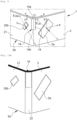
- radiofrequency device 1 With reference to the figure 1 , there is described a radiofrequency device 1 according to one embodiment.
- the radiofrequency device 1 comprises a first set of antennas 2 comprising a first antenna 2a and a second antenna 2b.
- the first antenna 2a and the second antenna 2b are flat in shape and both extend in a first plane 3.
- the first plane 3 is defined by an axis X and by an axis Z, the axis X and the axis Z being perpendicular.
- the first antenna 2a and the second antenna 2b are here positioned on a support 4 made of a dielectric material and extending in the first plane 3.
- the support 4 is here made of a plastic material having a dielectric permittivity greater than 1 (for example, the dielectric permittivity of the plastic material used is approximately equal to 3).
- the first antenna 2a operates in a first frequency band and the second antenna 2b operates in a second frequency band. It is understood here that an antenna operates in a frequency band (or at a frequency) means that said antenna is designed to transmit and/or receive, in an optimal manner, radio frequency signals in said frequency band (or respectively at said frequency).
- first frequency band and the second frequency band are here different but adjacent.
- adjacent means that the first band of frequencies and the second band of frequencies are separated by a frequency difference between about 0 MHz and about 1 GHz.
- said frequency deviation is the difference between the minimum frequency of the second band of frequencies and the maximum frequency of the first band of frequencies.
- the first antenna 2a could be a dual- band antenna operating at a frequency equal to 2.4 GHz and at a frequency equal to 5 GHz
- the second antenna 2b could be a simple mono-band antenna operating at a frequency of 6 GHz.
- the first antenna 2a could be a mono-band antenna operating in a 5 GHz frequency band, ranging from 5170 MHz to 5835 MHz
- the second antenna 2 b could be a mono-band antenna operating in a band of 6GHz frequency, ranging from 5925MHz to 7125MHz.
- the first antenna 2a and the second antenna 2b are here planar dipole antennas on supports of rectangular shapes.
- the first antenna 2a and the second antenna 2b both have an omnidirectional radiation pattern having the shape of a torus.
- the first antenna 2a generates a first maximum electric field on a first axis E 2a and the second antenna 2b generates a second maximum electric field on a second axis E 2b .
- the first axis E 2a is an axis of symmetry of the first antenna 2a parallel to the width thereof.
- the second axis E 2b is an axis of symmetry of the second antenna 2b parallel to the width thereof.
- first axis E 2a and the second axis E 2b are parallel.
- the radiofrequency device 1 further comprises a first insulator 5 of flat shape which extends in the first plane 3 between the first antenna 2a and the second antenna 2b.
- the first insulator 5 is here generally centered between the first antenna 2a and the second antenna 2b.
- the first insulator 5 is positioned on the support 4 and fixed by fixing means comprising for example dowels, glue or even screws.
- the first insulator 5 comprises a first branch 6 and a second branch 7.
- the first branch 6 and the second branch 7 of the first insulator 5 are here formed by flat and rectilinear tracks made of a conductive material, for example aluminum, copper or even iron.
- the second branch 7 of the first insulator 5 is here perpendicular to the first branch 6 of the first insulator 5 and extends from a central portion of said first branch 6.
- the first insulator 5 thus has a “T” shape.
- the “T” shape is simple and facilitates the manufacture of the first insulator 5 because it is a shape which can be cut with precision (in particular in a metal plate) and which is easily reproducible.
- the first branch 6 of the first insulator 5 is a transmission line which is in open circuit between a first end 6a and a second end 6b.
- the second branch 7 of the first insulator 5 is a stub which is in open circuit at a free end 7a.
- the first insulator 5 is thus a passive element which performs the reciprocal bandstop resonator function.
- the first insulator 5 thus has a transmission coefficient which is the same regardless of the direction of flow of an electric current flowing through its first branch 6 and its second branch 7.
- the first insulator 5 is not electrically connected.
- the first insulator 5 is not connected to an electrical ground plane.
- the first insulator 5 is thus electrically floating. It is noted in particular that this floating configuration of the first insulator 5 is particularly different from the solutions of the prior art. Indeed, according to art Previously, there are insulators mounted on PCBs (in English Printed Circuit Board), but the use of a PCB (which in particular has magnetic permeability) requires connecting said insulators to the electrical ground plane of said PCB.
- the first axis E 2a and the second axis E 2b are both oriented here at an angle equal to 45 degrees with respect to the second branch 7 of the first insulator 5.
- the first axis E 2a extends directly in the vicinity of the first end 6a of first branch 6 of first insulator 5.
- the dimensions of the first isolator 5 are predefined according to the space available, the environment in which it is used and a frequency band in which its influence must be maximum. It is indeed important to consider the environment in which the device 1 according to one embodiment is applied, and in particular the electrical parameters of the materials used (such as the dielectric permittivity) which impact the wavelengths, the resonance frequencies as well as as the characteristic impedances of the transmission lines (i.e. tracks).
- the first branch 6 of the first insulator 5 has a length approximately equal to at least a quarter of a first wavelength ⁇ A taking into account a medium in which the first insulator 5 extends.
- the first isolator 5 is here designed to attenuate the coupling by electromagnetic radiation between the first antenna 2a and the second antenna 2b in the first frequency band and in the second frequency band but more significantly in the first. frequency band (in which operates the first antenna 2a). If the medium in which the first insulator 5 extends is air, the first wavelength ⁇ A is calculated with a dielectric permittivity equal to 1.
- the first frequency band is a frequency band ranging from 5.1 GHz to 5.9 GHz
- the first central frequency ⁇ 1 is approximately equal to 5.5 GHz.
- the first isolator 5 is here designed to attenuate the coupling by electromagnetic radiation between the first antenna 2a and the second antenna 2b in a balanced (or equal) manner between the first frequency band and the second frequency band.
- the first frequency band is for example a frequency band called the 5 GHz band and the second frequency band is for example a frequency band called the 6 GHz band.
- ⁇ 1 is the first center frequency of the first frequency band (for example, 5.5 GHz)
- ⁇ 2 is a second center frequency which is centered between a maximum frequency and a frequency minimum of the second frequency band (for example 6.5 GHz).
- Other examples of dimensioning of the first branch 6 of the first insulator 5 can be obtained according to the isolation of the first frequency band or of the second frequency band sought.
- the second branch 7 of the first insulator 5 has a length approximately equal to a quarter of the first wavelength ⁇ A retained.
- the first wavelength ⁇ A selected corresponds to a first selected frequency which is for example equal to 6.2 GHz when insulation at the start of the frequency band called the 6 GHz band (UNII-5) is sought.
- the first frequency selected can also be, for example, dependent on the first central frequency ⁇ 1 of the first frequency band (in which the first antenna 2a operates) and on the second central frequency ⁇ 2 of the second frequency band (in which the second antenna 2b).
- the central frequency adopted is equal to ( ⁇ 1 + ⁇ 2 )/2.
- the dimensions of the first insulator 5, in particular the respective widths of the first branch 6 and of the second branch 7, are related to the characteristics of an antenna selected from among the first antenna 2a and the second antenna 2b.
- the respective dimensions of the first antenna 2a and of the second antenna 2b are considered in order to select the largest dimension(s). For example, when the first frequency band (in which the first antenna 2a operates) is the so-called 5GHz band frequency band and the second frequency band (in which the second antenna 2b operates) is the so-called 6GHz band frequency band , radiating strands or tracks of the first antenna 2a have larger dimensions or sizes than strands or radiating tracks of the second antenna 2b.
- the width of the radiating strands or tracks of the selected antenna makes it possible to determine the width of the first branch 6 and/or of the second branch 7 of the first insulator 5. If the first frequency band (first antenna 2a) is the band of frequencies called 5 GHz band and the second frequency band (second antenna 2b) is the frequency band called 6 GHz band, the respective widths of the first branch 6 and the second branch 7 of the first isolator 5 can be of the order of 2.5 mm-3mm.
- the first antenna 2a is selected to determine the dimensions of the first insulator 5 and the first antenna 2a is positioned on a PCB, itself resting on a first dielectric support (made for example with a plastic material), the assembly (the PCB and the first dielectric support) having a dielectric permittivity approximately equal to 4.3.
- the first insulator 5 is for its part, in one example, positioned on a second dielectric support (made for example with a plastic material) which can be identical to or different from the first dielectric support on which the first antenna 2a is positioned, and having a permittivity dielectric approximately equal to 3.
- the respective characteristic impedances of the first branch 6 and of the second branch 7 of the first insulator 5 are approximately equal to the characteristic impedance of the first antenna 2a.
- the first branch 6 and the second branch 7 of the first insulator 5 respectively have a width which ensures that the characteristic impedances respectively of said first branch 6 and of said second branch 7 are included in the interval [75 ⁇ , 120 ⁇ ]. This makes it possible to maximize an electric current flowing through said first branch 6 and said second branch 7 and thus to maximize the attenuation of the coupling by electromagnetic radiation.
- the first isolator 5 operates in the near field. Still considering that the first isolator 5 is arranged to more significantly attenuate the coupling by electromagnetic radiation between the first antenna 2a and the second antenna 2b in the first frequency band, a distance between the first end 6a of the first branch 6 of the first insulator 5 and the first axis E 2a is between 5 millimeters and 1 centimeter. This distance makes it possible to optimally limit the intensity of the electric field generated by the first antenna 2a and picked up by the second antenna 2b. In another example, this distance is greater than 1 centimeter, for example 1.5 centimeters.
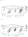
- the figure 2 , 3, 4 and 5 highlight the role of the first isolator 5 in the radiofrequency device 1.
- the first antenna 2a is here a Wi-Fi antenna operating in a frequency band ranging from 5.1 GHz to 5.9 GHz.
- the second antenna 2b is here a Wi-Fi antenna operating in a frequency band ranging from 5.9 GHz to 7.2 GHz.
- the first frequency band of the first antenna 2a and the second frequency band of the second antenna 2b are thus adjacent.
- curved field lines represent the orientation of the electric field in the first plane 3.
- intensity of said electric field (in Vm -1 ) is represented here in gray level.
- the first antenna 2a operates here in transmission, that is to say it transmits radiofrequency signals in its frequency band.
- Field lines 8 therefore represent here the orientation of the electric field generated by the first antenna 2a.
- the second antenna 2b is inactive here, that is to say that it neither emits nor receives any radiofrequency signal in its frequency band.
- the radiofrequency device 1 does not include the first isolator 5 ( figure 2 )
- the electric field generated by the first antenna 2a propagates without obstacle through the support 4 to the second antenna 2b.
- the second antenna 2b thus picks up a large part of the electric field generated by the first antenna 2a.
- the field lines 8 are thus concentrated on and in the vicinity of the second antenna 2b.
- the radiofrequency device 1 includes the first isolator 5 ( picture 3 )
- the electric field generated by the first antenna 2a is filtered, that is to say attenuated thanks to the reciprocal band-stop resonator function of said first insulator 5.
- the field lines 8 are thus concentrated on and in the vicinity of the first isolator 5 (and not in the vicinity of the second antenna 2b). More precisely, the electric field generated by the first antenna 2a is concentrated at the level of the first end 6a of the first branch 6 of the first insulator 5 and at the level of the free end 7a of the second branch 7 of the first insulator 5.
- the coupling by electromagnetic radiation between the first antenna 2a and the second antenna 2b is thus significantly reduced.
- the first insulator 5 modifies the near-field orientation of the electric field generated by the first antenna 2a.
- the first antenna 2a is here inactive and the second antenna 2b operates in transmission.
- Field lines 9 therefore represent here the orientation of the electric field generated by the second antenna 2b.
- the radiofrequency device 1 does not include the first isolator 5 ( figure 4 )
- the electric field generated by the second antenna 2b propagates without obstacle through the support 4 to the first antenna 2a.
- the field lines 9 are therefore concentrated on and in the vicinity of the first antenna 2a.
- the coupling by electromagnetic radiation between the first antenna 2a and the second antenna 2b is important.
- the radiofrequency device 1 includes the first isolator 5 ( figure 5 )
- the field lines 9 are concentrated at the level of the first end 6a and of the second end 6b of the first branch 6 of the first insulator 5 and at the level of the free end 7a of the second branch 7 of the first insulator 5.
- the number of field lines 9 in the vicinity of the first antenna 2a is greatly reduced.
- the coupling by electromagnetic radiation between the first antenna 2a and the second antenna 2b is therefore significantly reduced.
- the first isolator 5 has better performance when it is the first antenna 2a which is transmitting (compared to the case where it is the second antenna 2b which is transmitting). This result is logical because the first isolator 5 is here sized to operate in the vicinity of a maximum frequency of the first frequency band (ranging from 5.1 GHz to 5.9 GHz).
- FIG. 6 represents the amplitude in decibels of a parameter (in English Scattering Parameter ) S 21 as a function of the frequency.
- the parameter S 21 corresponds to the transmission coefficient between the second antenna 2b and the first antenna 2a.
- Curve 10 is the curve of parameter S 21 when the first insulator 5 is not present and curve 11 is the curve of parameter S 21 when the first insulator 5 is present.
- the first isolator 5 is here sized to attenuate the coupling by electromagnetic radiation between the first antenna 2a and the second antenna 2b in a frequency band ranging from 5 GHz to 7 GHz. It is clear that the first isolator 5 reduces the amplitude of the parameter S 21 in the frequency band for which it is dimensioned.
- the first isolator 5 therefore makes it possible to effectively reduce the coupling by electromagnetic radiation between the first antenna 2a and the second antenna 2b in the frequency band for which it is dimensioned.
- a Y axis is introduced here, perpendicular to the X axis and to the Z axis so that the three axes X, Y, Z form an orthogonal Cartesian coordinate system (space of dimension 3) defining three cuts, a first XZ cut (i.e. a cut according to the first plane 3), a second YZ cut and a third XY cut.
- FIG 7 represents a radiation pattern 12 of the first antenna 2a along the first XZ section, a radiation pattern 13 of the first antenna 2a along the second YZ section and a radiation pattern 14 of the first antenna 2a along the third XY section.
- the radiation patterns 12, 13, 14 correspond to the scenario of the figure 2 And 3 , that is to say that the first antenna 2a is transmitting (in the first frequency band ranging from 5.1 GHz to 5.9 GHz) and the second antenna 2 b is inactive. It is common in the radiofrequency domain to characterize an antenna using its radiation pattern which represents the angular distribution (in degrees) of the gain of said antenna (in isotropic decibels).
- the solid line curve corresponds to the far field directivity of the first antenna 2a when the first insulator 5 is not present and the dotted line curve corresponds to the field directivity distant from the first antenna 2a when the first insulator 5 is present.
- the radiation patterns 12, 13, 14 show that the first insulator 5 modifies the directivity in the far field of the first antenna 2a.
- the radiation pattern 12 according to the first section XZ shows that the directivity in the far field of the first antenna 2a is more homogeneous when the first insulator 5 is present (curve 12b).
- the gain of the first antenna 2a is approximately constant as a function of the propagation angle of the radiation emitted by said first antenna 2a. More precisely, when the first insulator 5 is not present (curve 12a), the maximum relative variation in gain of the first antenna 2a is of the order of 8 dBi, whereas when the first isolator 5 is present (curve 12b), the maximum relative variation in gain of the first antenna 2a is the order of 3dBi.
- the radiation pattern 13 according to the second section YZ does not reveal a significant shift in the directivity in the far field of the first antenna 2a.
- the radiation pattern 14 according to the third XY section shows that the maximum gain of the first antenna is shifted when the first insulator 5 is present. Indeed, when the first isolator 5 is not present (curve 14a), the gain of the first antenna 2a is maximum in the vicinity of an angle of 270 degrees whereas when the first isolator 5 is present (curve 14b), the gain of the first antenna 2a is maximum in the vicinity of an angle of 180 degrees.
- FIG 8 shows a radiation pattern 15 of the second antenna 2b along the first XZ section, a radiation pattern 16 of the second antenna 2b along the second YZ section and a radiation pattern 17 of the second antenna 2b along the third XY section.
- the radiation patterns 15, 16, 17 correspond to the scenario of the figures 4 and 5 , that is to say that the first antenna 2a is inactive and the second antenna 2b is transmitting (in the second frequency band ranging from 5.9 GHz to 7.2 GHz).
- the solid line curve corresponds to the directivity in the far field of the second antenna 2b when the first insulator 5 is not present and the dotted line curve corresponds to the far-field directivity of the second antenna 2b when the first insulator 5 is present.
- the radiation patterns 15, 16, 17 demonstrate that the first insulator 5 has a moderate influence on the directivity in the far field of the second antenna 2b. Indeed, the profile of the directivity in the far field of the second antenna 2b when the first insulator 5 is not present is generally similar to the profile of the directivity in the far field of the second antenna 2b when the first insulator 5 is present. This is due to the fact that the second axis E 2b of the second maximum electric field of the second antenna 2b does not extend directly in the vicinity of the first insulator 5.
- the dimensions of the first isolator 5 can be adjusted according to a target frequency band.
- first axis E 2a of the first maximum electric field (of the first antenna 2a) and the second axis E 2b of the second maximum electric field (of the second antenna 2b) could be perpendicular to the second branch 7 of the first insulator 5 .
- the radiofrequency device 1 further comprises at least one second isolator 18.
- the radiofrequency device 1 may further comprise a single second isolator 18.
- the second isolator 18 is positioned on one side of a particular antenna among the first antenna 2a or the second antenna 2b, said side of the particular antenna being opposed to the first insulator.
- the particular antenna is the first antenna 2a (which this time is positioned to the left of the antenna 2b, not represented on the figure 9 ).
- the second insulator 18 is used to modify and reorient the directivity in the far field of the first antenna 2a caused by the presence of the first insulator 5.
- the second insulator 18 is considered as a parasitic element influencing the cartography of the electric field on the support 54 .
- the first antenna 2a is here positioned on a support 54 comprising a first face extending along the first plane 3 and a second face extending along a second plane 21.
- the second plane 21 is defined by the Y axis and the axis Z.
- the second plane is therefore oriented by an angle ⁇ equal to 90 degrees with respect to the first plane 3. It should be noted that the angle ⁇ of inclination between the first plane 3 and the second plane 21 could be different 90 degrees
- the second insulator 18 is here positioned in a corner of the support 54 defined by an intersection of the first plane 3 and the second plane 21 via fixing means comprising for example riveting pins, glue or even screws.
- the second insulator 18 here comprises a single branch 19.
- the branch 19 of the second insulator 18 is here formed by a flat and rectilinear track made of a conductive material, for example aluminum, copper or even iron.
- the second insulator 18 thus has an “I” or slender shape.
- the "I" shape is simple and facilitates the manufacture of the second insulator 18 because it is a shape which can be cut with precision (in particular in a metal plate) and which is easily reproducible.
- branch 19 of second insulator 18 is a transmission line which is in open circuit between one end 19a and one end 19b.
- the second insulator is thus a passive element.
- the second insulator 18 is not electrically connected.
- the second insulator 18 is not connected to an electrical ground plane. The second insulator 18 is thus electrically floating.
- the radiofrequency device 1 further comprises a third antenna 20b.
- the third antenna 20b is flat in shape and here extends into the second plane 21.
- the third antenna 20b operates in a third frequency band.
- the third frequency band could be different from the first frequency band and the second frequency band but could also be similar to the first frequency band or the second frequency band.
- the third antenna 20b could be a single-band antenna operating in the so-called 6 GHz band frequency band.
- the third antenna 20b is here a planar dipole antenna of rectangular shape.
- the third antenna 20b has an omnidirectional radiation pattern having the shape of a torus.
- the third antenna 20b generates a third maximum electric field on a third axis E 20b .
- the position of the third antenna 20b in the second plane 21 is thus defined along the third axis E 20b .
- the second insulator 18 is here positioned in a corner of the support 54 between a antenna which is the first antenna 2a and the third antenna 20b.
- the second insulator 18 can be positioned in a secant plane 22 to the first plane 3 and to the second plane 21.
- the second insulator 18 is thus positioned at least partially on a chamfer of the support 54.
- the second insulator 18 can also form a rounded corner 23 between the first plane 3 and the second plane 21.
- the second insulator 18 is thus positioned at least partially on a fillet of the support 54.
- the second insulator 18 When it is placed between the first antenna 2a and the third antenna 20b, the second insulator 18 makes it possible to reduce coupling by electromagnetic radiation between said first antenna 2a and said third antenna 20b.
- the dimensions of the second isolator 18 are predefined according to the space available, the environment in which it is used and a frequency band in which its influence must be maximum.
- the dimensions of the second insulator 18 are indicated here in the case where the second insulator 18 is arranged to insulate the third antenna 20b from the electric field generated by the first antenna 2a.
- the branch 19 of the second insulator 18 has a length approximately equal to half of a second wavelength ⁇ B taking into account a medium in which the second insulator 18 extends.
- the second isolator 18 is here designed to attenuate the coupling by electromagnetic radiation between the first antenna 2a and the third antenna 20b in the first frequency band (in which the first antenna 2a operates) and in the third frequency band (in which the third antenna 20b operates) but more significantly in the first frequency band. If the medium in which the second insulator 18 extends is air, the second wavelength ⁇ B is calculated with a dielectric permittivity equal to 1.
- the second isolator 18 is here designed to attenuate the coupling by electromagnetic radiation between the first antenna 2a and the third antenna 20b in a balanced (or equal) manner between the first band of frequencies and the third band of frequencies.
- the first frequency band is for example the so-called 5 GHz frequency band and the third frequency band is for example the so-called 6 GHz frequency band.
- ⁇ 1 is the first center frequency of the first frequency band (for example, 5.5 GHz)
- ⁇ 3 is a third center frequency which is centered between a maximum frequency and a minimum frequency of the third frequency band (for example example 6.5GHz).
- Other examples of dimensioning of branch 19 of second isolator 18 can be obtained depending on the isolation of the first frequency band or the third frequency band sought.
- the dimensions of the second insulator 18, in particular the width of the branch 19 is related to the characteristics of an antenna selected from among the first antenna 2a and the third antenna 20b.
- the respective dimensions of the first antenna 2a and of the third antenna 20b are considered in order to select the largest dimension(s).
- the first frequency band (in which the first antenna 2a operates) is the frequency band known as the 5 GHz band
- the third frequency band (in which the third antenna 20b operates) is the frequency band known as the 6 GHz band
- the radiating strands or tracks of the first antenna 2a have larger dimensions or sizes than the radiating strands or tracks of the third antenna 20b.
- the width of the radiating strands or tracks of the selected antenna makes it possible to determine the width of the formwork 19 of the second insulator 18. If the first frequency band (first antenna 2a) is the frequency band called 5 GHz band and the third frequency band (third antenna 20b) is the frequency band called 6 GHz band, the width of the branch 19 of the second insulator 18 can be of the order of 2.5 mm-3 mm.
- the first antenna 2a is selected to determine the dimensions of the second insulator 18 and the first antenna 2a is positioned on a PCB, itself resting on a first dielectric support (made for example with a plastic material), the assembly (the PCB and the first dielectric support) having a dielectric permittivity approximately equal to 4.3.
- the second insulator 18 is for its part, in one example, positioned on a second dielectric support (made for example with a plastic material) which can be identical to or different from the first support on which the first antenna 2a is positioned, and having a dielectric permittivity approximately equal to 3. Due to the proximity of two different dielectric permittivities, and knowing that the first antenna 2a is selected to size the second insulator 18, the characteristic impedance of the branch 19 of the second insulator 18 is approximately equal to the impedance characteristic of the first antenna 2a.
- the branch 19 of the second insulator 18 has a width which ensures that the characteristic impedance of said branch 19 is included in the interval [75 ⁇ , 120 ⁇ ]. This makes it possible to maximize an electric current flowing through said branch 19 and thus to maximize the attenuation of the coupling by electromagnetic radiation.
- the width of the branch 19 of the second insulator 18 is at least equal to the width of the first branch 6 and/or of the second branch 7 of the first insulator 5. In yet another example, the width of the branch 19 of the second insulator 18 is approximately equal to twice the width of the first branch 6 and/or of the second branch 7 of the first insulator 5.
- the second isolator 18 operates in the near field. Still considering that the second insulator 18 is here arranged to insulate the third antenna 20b from the electric field generated by the first antenna 2a, a distance between the second insulator 18 and the first axis E 2a is between 5 millimeters and 1 centimeter. This distance makes it possible to optimally limit the intensity of the electric field generated by the first antenna 2a and picked up by the third antenna 20b. In another example, this distance is greater than 1 centimeter, for example 1.5 centimeters.
- the first antenna 2a is here a Wi-Fi antenna operating in a frequency band ranging from 5.1 GHz to 5.9 GHz, that is to say in the band of frequencies known as the 5 GHz band.
- the third antenna 20b is here a Wi-Fi antenna operating in a frequency band ranging from 5.9 GHz to 7.2 GHz, that is to say in the frequency band known as the 6 GHz band.
- the first frequency band of the first antenna 2a and the third frequency band of the third antenna 20b are thus adjacent.
- curved field lines 24 represent the orientation of the electric field in the first plane 3 and in the second plane 21.
- the intensity of said electric field (in Vm ⁇ 1 ) is represented here in gray level.
- the first antenna 2a operates here in transmission and the third antenna 20b is inactive here.
- THE figure 11 And 12 represent the orientation and intensity of the electric field generated by the first antenna 2a in the first plane 3.
- THE figure 13 And 14 represent the orientation and intensity of the electric field generated by the first antenna 2a in the second plane 21.
- the radiofrequency device 1 does not include the second insulator 18, the electric field generated by the first antenna 2a propagates through the support 54 according to the first axis E 2a ( figure 11 ).
- the field lines 24 are concentrated at the level of the third antenna 20b which shows that said third antenna 20b picks up a significant part of the electric field generated by the first antenna 2a ( figure 13 ).
- the radiofrequency device 1 includes the second isolator 18 ( figure 12 And figure 14 )
- the electric field generated by the first antenna 2a does not propagate along the first axis E 2a .
- the field lines 24 are thus concentrated at the level of the end 19a and the end 19b of the branch 19 of the second insulator 18.
- the field lines 24 are deflected from their initial orientation (i.e. say of their orientation when the second insulator 18 is not present).
- the deviation of the field lines 24 also makes it possible to attenuate the part of the electric field generated by the first antenna 2a picked up by the third antenna 20b.
- the second insulator 18 thus makes it possible to reduce the coupling by electromagnetic radiation between the first antenna 2a and the third antenna 20b.
- the parameter S 21 corresponds to the transmission coefficient between the third antenna 20b and the first antenna 2a.
- a curve 25 is the curve of the S parameter 21 when the second isolator 18 is not present and a curve 26 is the curve of the S parameter 21 when the second isolator 18 is present.
- the second isolator 18 is here sized to attenuate the coupling by electromagnetic radiation between the first antenna 2a and the third antenna 20b in a frequency band ranging from 5 GHz to 7 GHz.
- the second isolator 18 slightly reduces the amplitude of the parameter S 21 in the band of frequencies for which it is dimensioned.
- the second isolator 18 therefore makes it possible to slightly reduce the coupling by electromagnetic radiation between the first antenna 2a and the third antenna 20b in the frequency band for which it is dimensioned.
- FIG 16 shows a radiation pattern 27 of the first antenna 2a along the first XZ section, a radiation pattern 28 of the first antenna 2a along the second YZ section and a radiation pattern 29 of the first antenna 2a along the third XY section.
- the radiation patterns 27, 28, 29 correspond to the scenario of the figure 11 , 12 , 13 , 14 that is to say that the first antenna 2a is transmitting (in the first frequency band ranging from 5.1 GHz to 5.9 GHz) and the third antenna 20b is inactive.
- the solid line curve corresponds to the far field directivity of the first antenna 2a when the second insulator 18 is not present and the dotted line curve corresponds to the field directivity distant from the first antenna 2a when the second insulator 18 is present.
- the radiation patterns 27, 28, 29 show that the second insulator 18 modifies the directivity in the far field of the first antenna 2a.
- the radiation pattern 27 according to the first section XZ shows that the directivity in the far field of the first antenna 2a is globally more homogeneous when the second insulator 18 is present (curve 27b). More precisely, when the second isolator 18 is not present (curve 27a), the maximum relative gain variation of the first antenna 2a is of the order of 7dBi whereas when the second isolator 18 is present (curve 27b), the maximum relative gain variation of the first antenna 2a is of the order of 5dBi.
- the radiation pattern 28 according to the third XY section shows that the maximum of the gain of the first antenna 2a is shifted when the second insulator 18 is present. Indeed, when the second isolator 18 is not present (curve 28a), the gain of the first antenna 2a is maximum for an angle interval ranging from 210 degrees to 300 degrees whereas when the second isolator 18 is present ( curve 28b), the gain of the first antenna 2a is maximum in the vicinity of a first angle equal to 0 degrees and in the vicinity of a second angle equal to 180 degrees.
- FIG 17 shows a radiation pattern 30 of the third antenna 20b along the first XZ section, a radiation pattern 31 of the third antenna 20b along the second YZ section and a radiation pattern 32 of the third antenna 20b along the third XY section.
- the radiation patterns 30, 31, 32 correspond to the case in which the third antenna 20b is transmitting (in the third frequency band ranging from 5.9 GHz to 7.2 GHz).
- the solid line curve corresponds to the far field directivity of the third antenna 20b when the second insulator 18 is not present and the dotted line curve corresponds to the field directivity away from the third antenna 20b when the second insulator 18 is present.
- the radiation patterns 30, 31, 32 show that the second insulator 18 has an almost negligible influence on the directivity in the far field of the third antenna 20b. Indeed, the profiles of the far-field directivity as well as the gain values of the third antenna 20b when the second isolator 18 is not present and when the second isolator 18 and present are globally similar. This is due to the fact that the third axis E 20b of the third maximum electric field of the third antenna 20b does not extend directly in the vicinity of the second insulator 18.
- the attenuation produced by the second insulator 18 is generally lower than that produced by the first insulator 5. This is explained by the fact that the second insulator 18 can be seen as a parasitic wave director element .
- first isolator 5 and/or of the second isolator 18 can be adjusted according to a target frequency band.
- the radiofrequency device 1 further comprises a second set of antennas 20 comprising the third antenna 20b and a fourth antenna 20a.
- the second set of antennas 20 is here similar to the first set of antennas 2.
- the third antenna 20b is similar to the second antenna 2b and the fourth antenna 20a is similar to the first antenna 2a.
- the third antenna 20b and the fourth antenna 20a extend in the second plane 21 and are positioned on the support 54.
- a third isolator 33 similar to the first isolator 5 is positioned between the third antenna 20b and the fourth antenna 20a.
- the third insulator 33 is thus arranged to reduce coupling by electromagnetic radiation between the third antenna 20b and the fourth antenna 20a.
- the radiofrequency device 1 comprises two first sets of antennas 2, two second sets of antennas 20, two first isolators 5, two third isolators 33 and four second isolators 18.
- the radiofrequency device 1 here rests on a cylindrical support 40 of square section (with slightly rounded corners).
- the cylindrical support 40 has two first faces 40a, the two first faces 40a being parallel to each other; and two second faces 40b, the two second faces 40b being parallel to each other.
- Cylindrical support 40 thus has four corners 41, 42, 43, 44. Cylindrical support 40 thus has the overall shape of a rectangular crown.
- the cylindrical support 40 is made from a material having a dielectric permittivity greater than 1.
- the cylindrical support 40 is made from a plastic material or from a polymer material.
- a first set of antennas 2 is positioned on each of the first two faces 40a of the cylindrical support 40.
- a first insulator 5 is positioned between the first antenna 2a and the second antenna 2b of each of the first two sets of antennas 2.
- a second set of antennas 20 is positioned on each of the two second faces 40b of the cylindrical support 40.
- a third insulator 33 is positioned between the third antenna 20b and the fourth antenna 20a of each of the two second sets of antennas 20.
- a second insulator 18 is positioned on each of the four corners, 41, 42, 43, 44 of the cylindrical support 40.
- a first group of antennas G1 and a second group of antennas G2 are defined.
- the first group of antennas G1 comprises the first antenna 2a of each of the first two sets of antennas 2 and the fourth antenna 20a of each of the two second sets of antennas 20.
- the first group of antennas G1 thus comprises four antennas.
- the antennas of group G1 are here dual-band Wi-Fi antennas operating in a frequency band called the 2.4GHz band and in the frequency band called the 5GHz band.
- the antennas of group G1 are antennas according to 802.11 technology and are single-band and operate in the so-called 5 GHz band frequency band.
- the antennas of group G1 are antennas according to 802.11 technology and are single-band and operate in the frequency band known as the 6 GHz band.
- the antennas of group G1 are tri-band antennas comprising different subsets of electrical conductors allowing said antennas of group G1 to operate both in the frequency band known as the 2.4 GHz band, in the band of frequencies called 5GHz band and in the frequency band called 6GHz band.
- the second group of antennas G2 comprises the second antenna 2b of each of the two first sets of antennas 2 and the third antenna 20b of each of the two second sets of antennas 20.
- the second group of antennas G2 thus comprises four antennas.
- Group G2 antennas Here are mono-band Wi-Fi antennas operating in the frequency band known as the 6GHz band.
- the first two insulators 5, the two third insulators 33 and the four second insulators 18 will be referred to as an isolation device.
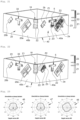
- THE figures 19, 20 , 21, 22 highlight the role of the first isolator 5, the second isolator 18 and the third isolator 33 in the radio frequency device 1.
- the first antenna 2a which belongs to the first group of antenna G1 is here in transmission.
- the intensity of the electric field (in Vm -1 ) is represented here according to three distinct zones.
- a first zone Z1 from 0 Vm -1 to 1000 Vm -1 a second zone Z2 from 1000 Vm -1 to 1400 Vm -1 and a third zone Z3 from 1400 Vm -1 to about 2360 V.m -1 .
- the first antenna 2a (belonging to the first group of antennas G1) is transmitting and the other antennas are inactive.
- the isolation device When the isolation device is present ( figure 21 ), the electric field generated by the first antenna 2a is picked up by the isolation device, here in particular by the first insulator 5. The coupling by electromagnetic radiation between the antennas of the radiofrequency device 1 is thus greatly reduced.
- the second antenna 2b (belonging to the second group of antennas G2) is transmitting and the other antennas are inactive.
- the isolation device When the isolation device is present ( figure 22 ), the electric field generated by the second antenna 2b is picked up by the isolation device, here in particular by the second insulator 18. The coupling by electromagnetic radiation between the antennas of the radio frequency device 1 is thus greatly reduced.
- FIG 23 represents a radiation pattern 46 along the first XZ section, a radiation pattern 47 along the second YZ section and a radiation pattern 48 along the third XY section of the antennas of the first group of antennas G1. More precisely, the radiation patterns 46, 47, 48 are here average combined gain radiation patterns.
- the solid line curve corresponds to the combined far-field directivity of the antennas of the first group of antennas G1 when the isolation device is not present and the dotted line curve corresponds to the combined far-field directivity of the antennas of the first group of antennas G1 when the isolation device is present.
- the radiation patterns 46, 47, 48 demonstrate that the isolation device makes it possible to substantially homogenize the directivity in the far field of the antennas of the first group of antennas G1.
- FIG 24 represents a radiation pattern 49 along the first XZ section, a radiation pattern 50 along the second YZ section and a radiation pattern 51 according to the third section XY of the antennas of the second group of antennas G2. More precisely, the radiation patterns 49, 50, 51 are here average combined gain radiation patterns.
- the solid line curve corresponds to the combined far-field directivity of the antennas of the second group of antennas G2 when the isolation device is not present and the dotted line curve corresponds to the combined far-field directivity of the antennas of the second group of antennas G2 when the isolation device is present.
- the radiation patterns 49, 50, 51 demonstrate that the isolation device has a limited influence on the directivity in the far field of the antennas of the second group of antennas G2.
- the isolation device thus has a greater influence on a frequency band in which the antennas of the first group of antennas G1 operate than on a frequency band in which the antennas of the second group of antennas G2 operate.
- the radio frequency device 1 therefore makes it possible to respond to the isolation constraints between antennas when adjacent frequency bands are used while guaranteeing that the radiation pattern of said antennas is omnidirectional (that is to say that the angular distribution of the gain of said antennas is homogeneous).
- the radio frequency device does not require a particular antenna technology (for example, ceramic antennas) and can be implemented using antennas having conventional dimensions.
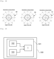
- the radiofrequency device 1 is here integrated into a MIMO system 101 (in English Multiple-Input Multiple-Output ) which itself is integrated into an electronic equipment 100.
- the MIMO system 101 comprises a radiofrequency transmitter 102 and a radio frequency receiver 103 which are both connected to the radio frequency device 1 according to different embodiments, such as for example the radio frequency device 1 comprising the first sets of antennas 2 and the second sets of antennas 20.
- the radio frequency transmitter 102 is arranged to transmit electrical signals to the radiofrequency device 1.
- the radiofrequency receiver 103 is arranged to receive electrical signals from radiofrequency signals received by the radiofrequency device 1.
- the radiofrequency device 1 is integrated in particular into an electronic equipment 100 which is a residential gateway.
- the residential walkway here has a tower shape.
- the radiofrequency device applies beneficially to any electronic equipment requiring the combination of multiple radiofrequency interfaces (in particular communication technologies using different but adjacent frequency bands) and/or requiring a plurality of transmission paths on the same frequency band, all in a small space.
- the first insulator 5 here has a “T” shape but that it is entirely possible for the first insulator 5 to have another shape.
- the first insulator 5 could comprise three branches, all three of which are electrically conductive, arranged so that said first insulator 5 has a "Y" shape.
- the shape of the first insulator 5 can be adapted according, for example, to the specified performance of the radio frequency device 1. The same is true for the third insulator 33 which is similar to the first insulator 5.
- the second insulator 18 here has an "I" shape but it is quite possible that the second insulator 18 has another shape. It should be noted that the shape of the second isolator 18 can be adapted according, for example, to the specified performance of the radio frequency device 1.
- the first insulator 5 is not necessarily fixed on the same support as that on which the first antenna 2a and the second antenna 2b are fixed.
- the first insulator 5 could be fixed on a first auxiliary support, different from the support 4 or from the support 54 and thus be maintained “in the air” between the first antenna 2a and the second antenna 2b.
- the third insulator 33 which is similar to the first insulator 5.
- the third insulator 33 is therefore not necessarily fixed on the same support as that on which the third antenna 20b and the fourth antenna 20a are fixed.
- the second insulator 18 is not necessarily attached to a corner of the support 54.
- the second insulator 18 could be attached to a second additional support, different from the support 54 and thus be kept in the air, for example on one side of the first antenna 2a or of the second antenna 2b opposite the first insulator 5.
- first antenna 2a and the second antenna 2b are not necessarily fixed on the same support.
- the first antenna 2a and the second antenna 2b could respectively be fixed on separate supports while extending in the same plane.
Landscapes
- Variable-Direction Aerials And Aerial Arrays (AREA)
- Details Of Aerials (AREA)
- Input Circuits Of Receivers And Coupling Of Receivers And Audio Equipment (AREA)
- Aerials With Secondary Devices (AREA)
Applications Claiming Priority (1)
| Application Number | Priority Date | Filing Date | Title |
|---|---|---|---|
| FR2110982 | 2021-10-15 |
Publications (2)
| Publication Number | Publication Date |
|---|---|
| EP4167378A1 true EP4167378A1 (de) | 2023-04-19 |
| EP4167378B1 EP4167378B1 (de) | 2025-11-26 |
Family
ID=80448590
Family Applications (1)
| Application Number | Title | Priority Date | Filing Date |
|---|---|---|---|
| EP22200222.2A Active EP4167378B1 (de) | 2021-10-15 | 2022-10-07 | Isolierte hochfrequenzantennenanordnung |
Country Status (4)
| Country | Link |
|---|---|
| US (1) | US12230885B2 (de) |
| EP (1) | EP4167378B1 (de) |
| CN (1) | CN115986399A (de) |
| CA (1) | CA3178714A1 (de) |
Families Citing this family (1)
| Publication number | Priority date | Publication date | Assignee | Title |
|---|---|---|---|---|
| CN118040309A (zh) * | 2022-11-07 | 2024-05-14 | 英业达科技有限公司 | 天线装置 |
Citations (4)
| Publication number | Priority date | Publication date | Assignee | Title |
|---|---|---|---|---|
| KR101403592B1 (ko) * | 2012-11-30 | 2014-06-03 | 주식회사 엘트로닉스 | 안테나 장치 |
| CN104979635A (zh) * | 2014-04-03 | 2015-10-14 | 中国移动通信集团公司 | 一种阵列天线 |
| US20160156110A1 (en) * | 2014-11-28 | 2016-06-02 | Galtronics Corporation Ltd. | Antenna isolator |
| US20190165467A1 (en) * | 2017-11-30 | 2019-05-30 | Metal Industries Research & Development Centre | Multi-antenna system using non-radiation coupling edges to achieve isolation |
-
2022
- 2022-10-07 CA CA3178714A patent/CA3178714A1/fr active Pending
- 2022-10-07 EP EP22200222.2A patent/EP4167378B1/de active Active
- 2022-10-14 US US17/966,308 patent/US12230885B2/en active Active
- 2022-10-17 CN CN202211267823.1A patent/CN115986399A/zh active Pending
Patent Citations (4)
| Publication number | Priority date | Publication date | Assignee | Title |
|---|---|---|---|---|
| KR101403592B1 (ko) * | 2012-11-30 | 2014-06-03 | 주식회사 엘트로닉스 | 안테나 장치 |
| CN104979635A (zh) * | 2014-04-03 | 2015-10-14 | 中国移动通信集团公司 | 一种阵列天线 |
| US20160156110A1 (en) * | 2014-11-28 | 2016-06-02 | Galtronics Corporation Ltd. | Antenna isolator |
| US20190165467A1 (en) * | 2017-11-30 | 2019-05-30 | Metal Industries Research & Development Centre | Multi-antenna system using non-radiation coupling edges to achieve isolation |
Also Published As
| Publication number | Publication date |
|---|---|
| CA3178714A1 (fr) | 2023-04-15 |
| EP4167378B1 (de) | 2025-11-26 |
| US20230120328A1 (en) | 2023-04-20 |
| US12230885B2 (en) | 2025-02-18 |
| CN115986399A (zh) | 2023-04-18 |
Similar Documents
| Publication | Publication Date | Title |
|---|---|---|
| EP0890226B1 (de) | Basisfunkstation mit zirkularpolarisierten antennen | |
| EP1078418A1 (de) | Antenne für funkfeststation | |
| EP0825673A1 (de) | Ebene gedruckte Antenne mit kurzgeschlossenen übereinanderliegenden Elementen | |
| FR2709833A1 (fr) | Instrument d'écoute large bande et bande basse pour applications spatiales. | |
| US11881611B2 (en) | Differential fed dual polarized tightly coupled dielectric cavity radiator for electronically scanned array applications | |
| EP2087553A2 (de) | Antenne mit mehreren sektoren | |
| EP1466384B1 (de) | Einrichtung zum empfangen und/oder emittieren elektromagnetischer wellen mit strahlungs-diversity | |
| FR3091045A1 (fr) | Antenne fil-plaque monopolaire pour connexion differentielle | |
| EP1589608A1 (de) | RF kompakte Antenne | |
| EP1188202B1 (de) | Anordnung zur übertragung und/oder zum empfang von signalen | |
| EP4167378B1 (de) | Isolierte hochfrequenzantennenanordnung | |
| WO2008028892A1 (fr) | Systeme multi-antenne a diversite de polarisation | |
| CA2800952C (fr) | Antenne compacte large bande a tres faible epaisseur et a double polarisations lineaires orthogonales operant dans les bandes v/uhf | |
| EP3815184A1 (de) | Hochfrequenzübertragungsvorrichtung mit einem einen strahlenden teil einer antenne bildenden befestigungselement | |
| FR2831734A1 (fr) | Dispositif pour la reception et/ou l'emission de signaux electromagnetiques a diversite de rayonnement | |
| EP3175509B1 (de) | Logarithmisch-periodische antenne mit breitem frequenzband | |
| EP3942649B1 (de) | Kompakte richtantenne, vorrichtung mit einer solchen antenne | |
| FR2871619A1 (fr) | Antenne large bande et a rayonnement omnidirectionnel | |
| EP2889955B1 (de) | Kompaktantennenstruktur für Telekommunikationen über Satelliten | |
| FR2930844A1 (fr) | Antenne rf d'emission et/ou de reception comportant des elements rayonnants excites par couplage electromagnetique sans contact | |
| WO2000049677A1 (fr) | Station radio a antenne a polarisation circulaire | |
| EP4485687B1 (de) | Durch hindernisvorspannung anpassbares strahlungsdiagramm | |
| FR3013909A1 (fr) | Cornet, antennaire elementaire, structure antennaire et procede de telecommunication associes | |
| EP4550578A1 (de) | Superdirektive schleifenantenne | |
| Tianang | Simulteneous Transmit and Receive (STAR) Antennas for Geosatellites and Shared-Antenna Platforms |
Legal Events
| Date | Code | Title | Description |
|---|---|---|---|
| PUAI | Public reference made under article 153(3) epc to a published international application that has entered the european phase |
Free format text: ORIGINAL CODE: 0009012 |
|
| STAA | Information on the status of an ep patent application or granted ep patent |
Free format text: STATUS: EXAMINATION IS IN PROGRESS |
|
| 17P | Request for examination filed |
Effective date: 20221007 |
|
| AK | Designated contracting states |
Kind code of ref document: A1 Designated state(s): AL AT BE BG CH CY CZ DE DK EE ES FI FR GB GR HR HU IE IS IT LI LT LU LV MC ME MK MT NL NO PL PT RO RS SE SI SK SM TR |
|
| RBV | Designated contracting states (corrected) |
Designated state(s): AL AT BE BG CH CY CZ DE DK EE ES FI FR GB GR HR HU IE IS IT LI LT LU LV MC ME MK MT NL NO PL PT RO RS SE SI SK SM TR |
|
| RAP3 | Party data changed (applicant data changed or rights of an application transferred) |
Owner name: SAGEMCOM BROADBAND SAS |
|
| GRAP | Despatch of communication of intention to grant a patent |
Free format text: ORIGINAL CODE: EPIDOSNIGR1 |
|
| STAA | Information on the status of an ep patent application or granted ep patent |
Free format text: STATUS: GRANT OF PATENT IS INTENDED |
|
| INTG | Intention to grant announced |
Effective date: 20250211 |
|
| GRAJ | Information related to disapproval of communication of intention to grant by the applicant or resumption of examination proceedings by the epo deleted |
Free format text: ORIGINAL CODE: EPIDOSDIGR1 |
|
| STAA | Information on the status of an ep patent application or granted ep patent |
Free format text: STATUS: EXAMINATION IS IN PROGRESS |
|
| GRAP | Despatch of communication of intention to grant a patent |
Free format text: ORIGINAL CODE: EPIDOSNIGR1 |
|
| STAA | Information on the status of an ep patent application or granted ep patent |
Free format text: STATUS: GRANT OF PATENT IS INTENDED |
|
| INTC | Intention to grant announced (deleted) | ||
| INTG | Intention to grant announced |
Effective date: 20250623 |
|
| GRAS | Grant fee paid |
Free format text: ORIGINAL CODE: EPIDOSNIGR3 |
|
| GRAA | (expected) grant |
Free format text: ORIGINAL CODE: 0009210 |
|
| STAA | Information on the status of an ep patent application or granted ep patent |
Free format text: STATUS: THE PATENT HAS BEEN GRANTED |
|
| AK | Designated contracting states |
Kind code of ref document: B1 Designated state(s): AL AT BE BG CH CY CZ DE DK EE ES FI FR GB GR HR HU IE IS IT LI LT LU LV MC ME MK MT NL NO PL PT RO RS SE SI SK SM TR |
|
| REG | Reference to a national code |
Ref country code: CH Ref legal event code: F10 Free format text: ST27 STATUS EVENT CODE: U-0-0-F10-F00 (AS PROVIDED BY THE NATIONAL OFFICE) Effective date: 20251126 Ref country code: GB Ref legal event code: FG4D Free format text: NOT ENGLISH |
|
| RIN1 | Information on inventor provided before grant (corrected) |
Inventor name: KARTOUT, MADANI |
|
| REG | Reference to a national code |
Ref country code: IE Ref legal event code: FG4D Free format text: LANGUAGE OF EP DOCUMENT: FRENCH |
|
| REG | Reference to a national code |
Ref country code: DE Ref legal event code: R096 Ref document number: 602022025547 Country of ref document: DE |
|
| REG | Reference to a national code |
Ref country code: NL Ref legal event code: MP Effective date: 20251126 |
|
| PG25 | Lapsed in a contracting state [announced via postgrant information from national office to epo] |
Ref country code: ES Free format text: LAPSE BECAUSE OF FAILURE TO SUBMIT A TRANSLATION OF THE DESCRIPTION OR TO PAY THE FEE WITHIN THE PRESCRIBED TIME-LIMIT Effective date: 20251126 |
|
| REG | Reference to a national code |
Ref country code: LT Ref legal event code: MG9D |
|
| PG25 | Lapsed in a contracting state [announced via postgrant information from national office to epo] |
Ref country code: NO Free format text: LAPSE BECAUSE OF FAILURE TO SUBMIT A TRANSLATION OF THE DESCRIPTION OR TO PAY THE FEE WITHIN THE PRESCRIBED TIME-LIMIT Effective date: 20260226 |
|
| PG25 | Lapsed in a contracting state [announced via postgrant information from national office to epo] |
Ref country code: FI Free format text: LAPSE BECAUSE OF FAILURE TO SUBMIT A TRANSLATION OF THE DESCRIPTION OR TO PAY THE FEE WITHIN THE PRESCRIBED TIME-LIMIT Effective date: 20251126 Ref country code: HR Free format text: LAPSE BECAUSE OF FAILURE TO SUBMIT A TRANSLATION OF THE DESCRIPTION OR TO PAY THE FEE WITHIN THE PRESCRIBED TIME-LIMIT Effective date: 20251126 Ref country code: AT Free format text: LAPSE BECAUSE OF FAILURE TO SUBMIT A TRANSLATION OF THE DESCRIPTION OR TO PAY THE FEE WITHIN THE PRESCRIBED TIME-LIMIT Effective date: 20251126 |
|
| REG | Reference to a national code |
Ref country code: AT Ref legal event code: MK05 Ref document number: 1862062 Country of ref document: AT Kind code of ref document: T Effective date: 20251126 |
|
| PG25 | Lapsed in a contracting state [announced via postgrant information from national office to epo] |
Ref country code: NL Free format text: LAPSE BECAUSE OF FAILURE TO SUBMIT A TRANSLATION OF THE DESCRIPTION OR TO PAY THE FEE WITHIN THE PRESCRIBED TIME-LIMIT Effective date: 20251126 |
|
| PG25 | Lapsed in a contracting state [announced via postgrant information from national office to epo] |
Ref country code: RS Free format text: LAPSE BECAUSE OF FAILURE TO SUBMIT A TRANSLATION OF THE DESCRIPTION OR TO PAY THE FEE WITHIN THE PRESCRIBED TIME-LIMIT Effective date: 20260226 |
|
| PG25 | Lapsed in a contracting state [announced via postgrant information from national office to epo] |
Ref country code: IS Free format text: LAPSE BECAUSE OF FAILURE TO SUBMIT A TRANSLATION OF THE DESCRIPTION OR TO PAY THE FEE WITHIN THE PRESCRIBED TIME-LIMIT Effective date: 20260326 |
|
| PG25 | Lapsed in a contracting state [announced via postgrant information from national office to epo] |
Ref country code: PT Free format text: LAPSE BECAUSE OF FAILURE TO SUBMIT A TRANSLATION OF THE DESCRIPTION OR TO PAY THE FEE WITHIN THE PRESCRIBED TIME-LIMIT Effective date: 20260326 |
|
| PG25 | Lapsed in a contracting state [announced via postgrant information from national office to epo] |
Ref country code: PL Free format text: LAPSE BECAUSE OF FAILURE TO SUBMIT A TRANSLATION OF THE DESCRIPTION OR TO PAY THE FEE WITHIN THE PRESCRIBED TIME-LIMIT Effective date: 20251126 |
|
| PG25 | Lapsed in a contracting state [announced via postgrant information from national office to epo] |
Ref country code: LV Free format text: LAPSE BECAUSE OF FAILURE TO SUBMIT A TRANSLATION OF THE DESCRIPTION OR TO PAY THE FEE WITHIN THE PRESCRIBED TIME-LIMIT Effective date: 20251126 |