EP4167445A1 - Dispositif de soutien de moteurs électriques et ensemble formant un moteur électrique - Google Patents
Dispositif de soutien de moteurs électriques et ensemble formant un moteur électrique Download PDFInfo
- Publication number
- EP4167445A1 EP4167445A1 EP21822768.4A EP21822768A EP4167445A1 EP 4167445 A1 EP4167445 A1 EP 4167445A1 EP 21822768 A EP21822768 A EP 21822768A EP 4167445 A1 EP4167445 A1 EP 4167445A1
- Authority
- EP
- European Patent Office
- Prior art keywords
- straight section
- motor
- support apparatus
- motor support
- long side
- Prior art date
- Legal status (The legal status is an assumption and is not a legal conclusion. Google has not performed a legal analysis and makes no representation as to the accuracy of the status listed.)
- Withdrawn
Links
Images

Classifications
-
- H—ELECTRICITY
- H02—GENERATION; CONVERSION OR DISTRIBUTION OF ELECTRIC POWER
- H02K—DYNAMO-ELECTRIC MACHINES
- H02K5/00—Casings; Enclosures; Supports
- H02K5/24—Casings; Enclosures; Supports specially adapted for suppression or reduction of noise or vibrations
-
- H—ELECTRICITY
- H02—GENERATION; CONVERSION OR DISTRIBUTION OF ELECTRIC POWER
- H02K—DYNAMO-ELECTRIC MACHINES
- H02K5/00—Casings; Enclosures; Supports
- H02K5/26—Means for adjusting casings relative to their supports
-
- F—MECHANICAL ENGINEERING; LIGHTING; HEATING; WEAPONS; BLASTING
- F16—ENGINEERING ELEMENTS AND UNITS; GENERAL MEASURES FOR PRODUCING AND MAINTAINING EFFECTIVE FUNCTIONING OF MACHINES OR INSTALLATIONS; THERMAL INSULATION IN GENERAL
- F16M—FRAMES, CASINGS OR BEDS OF ENGINES, MACHINES OR APPARATUS, NOT SPECIFIC TO ENGINES, MACHINES OR APPARATUS PROVIDED FOR ELSEWHERE; STANDS; SUPPORTS
- F16M1/00—Frames or casings of engines, machines or apparatus; Frames serving as machinery beds
- F16M1/04—Frames or casings of engines, machines or apparatus; Frames serving as machinery beds for rotary engines or similar machines
-
- H—ELECTRICITY
- H02—GENERATION; CONVERSION OR DISTRIBUTION OF ELECTRIC POWER
- H02K—DYNAMO-ELECTRIC MACHINES
- H02K15/00—Processes or apparatus specially adapted for manufacturing, assembling, maintaining or repairing of dynamo-electric machines
- H02K15/14—Casings; Enclosures; Supports
-
- F—MECHANICAL ENGINEERING; LIGHTING; HEATING; WEAPONS; BLASTING
- F16—ENGINEERING ELEMENTS AND UNITS; GENERAL MEASURES FOR PRODUCING AND MAINTAINING EFFECTIVE FUNCTIONING OF MACHINES OR INSTALLATIONS; THERMAL INSULATION IN GENERAL
- F16M—FRAMES, CASINGS OR BEDS OF ENGINES, MACHINES OR APPARATUS, NOT SPECIFIC TO ENGINES, MACHINES OR APPARATUS PROVIDED FOR ELSEWHERE; STANDS; SUPPORTS
- F16M1/00—Frames or casings of engines, machines or apparatus; Frames serving as machinery beds
- F16M1/08—Frames or casings of engines, machines or apparatus; Frames serving as machinery beds characterised by being built-up of sheet material or welded parts
Definitions
- the present disclosure relates to the field of motor technologies, and more specifically, to a motor support apparatus and a motor assembly.
- a drive motor used in a multi-stage centrifugal compressor ZH is mounted in a mounting manner B3, i.e., generally horizontally mounted.
- a compressor element and the drive motor are directly connected through a shaft coupling.
- the motor is connected to a motor support via four bottom feet.
- a motor support used on the multi-stage centrifugal compressor ZH is rectangular.
- a square tube is mainly used for the steel of a motor support, and four bosses are welded on the square tube to be connected to the four bottom feet of the motor.
- a motor support structure in the prior art is usually made of a square tube, the adjustable range of the motor bracket's height is limited.
- the motor support structure may not be suitable for a plurality of motors having different shaft heights, which results in technical problems like poor universality, etc. Therefore, the present disclosure develops and designs a motor support apparatus and a motor assembly.
- the present disclosure provides a motor support apparatus and a motor assembly, aiming to solve a technical problem that an adjustable range of a motor bracket's height is limited because a motor support structure in the prior art is usually a square tube, and the motor support structure may not be suitable for a plurality of motors with different shaft heights and thus have poor universality.
- the motor support apparatus includes at least one beam structure.
- the beam structure is formed by bending a metal plate.
- the metal plate includes a first long side and a second long side that are relative to each other.
- the bending includes bending the first long side towards the second long side and bending the second long side towards the first long side.
- the bent first long side is formed as a first free end side of the beam structure.
- the bent second long side is formed as a second free end side of the beam structure.
- a spacing is present between the first free end side and the second free end side, in such a manner that a cross section of the beam structure is in an unclosed shape.
- the beam structure is in a structural form of a U-shaped beam, with a U-shaped cross section of the beam; and/or a semi-closed internal cavity structure is formed as by bending the beam structure, with a support plate inside.
- a bent structure having a plurality of sections connected to each other is formed along a length direction of the beam structure thereof; or a curved structure is formed along the length direction of the beam structure thereof.
- the bent structure having the plurality of connected sections includes a first straight section, a second straight section, and a third straight section.
- the second straight section is connected between the first straight section and the third straight section in such a manner that the first straight section, the second straight section, and the third straight section are sequentially connected.
- the first straight section and the second straight section form a bend at the junction thereof.
- the second straight section and the third straight section (1c) form a bend at the junction thereof.
- the beam structure includes a first beam and a second beam.
- a second straight section of the first beam is connected to a second straight section of the second beam;
- a first straight section of the first beam extends away with respect to the second beam, and a third straight section of the first beam also extends away with respect to the second beam;
- a first straight section of the second beam extends away with respect to the first beam, and a third straight section of the second beam extends away with respect to the first beam.
- the first beam and the second beam have a same structure and a same shape, and they are connected to each other symmetrically; and/or the second straight section of the first beam is permanently connected to the second straight section of the second beam.
- a first reinforcing rib is provided at the junction of the first straight section and the second straight section, a shape of the first reinforcing rib matching a shape of the bend at the junction of the first straight section and the second straight section; and/or a second reinforcing rib is provided at the junction of the second straight section and the third straight section, a shape of the second reinforcing rib matching a shape of the bend at the junction of the second straight section and the third straight section.
- the first reinforcing rib is arranged on a side of the unclosed shape's opening of the beam structure, and has one end permanently connected to the first free end side and the other end permanently connected to the second free end side; and/or the second reinforcing rib is arranged on a side of the unclosed shape's opening of the beam structure, and has one end permanently connected to the first free end side and the other end permanently connected to the second free end side.
- the motor assembly further includes a motor base plate and at least one shock pad.
- the motor base plate is mounted at a bottom of the motor support apparatus.
- the at least one shock pad is provided between the motor base plate and the motor support apparatus.
- the motor support apparatus and the motor assembly provided by the present disclosure have the following beneficial effects.
- the motor support apparatus is configured as the at least one beam structure.
- the beam structure is a structure formed by bending two long sides of a rectangular metal plate towards each other, and the structure formed by the bending is not closed. Therefore, in the beam structure of present disclosure, the bent side could be adjusted depending on different motor axial heights, so that a vertical height of the beam structure could be adjusted according to actual requirements, Therefore, an adjustable range of the motor support apparatus's height is enlarged, better satisfying mounting requirements of different shaft heights of drive motors, and effectively improving universality of the motor support apparatus.
- the motor support apparatus is suitable for a plurality of motors having different shaft heights.
- the two multi-section bent beam structures which are arranged as connecting to each other back-to-back and extending oppositely to each other, effectively reduce a quantity of the beam structures in use, effectively reduce the materials, reduce the costs, improve economical efficiency of products, and save space of the whole machine, while satisfying the condition of being permanently connected to the motor at four different positions.
- An open U-shaped support of the present disclosure enables easier assembling of bolts which facilitates assembly, disassembly, operation and processing for after-sales service personnel, conveniently for installing and maintaining.
- the reference numerals in the drawings are denoted as: 100, motor support apparatus; 1, beam structure; 11, first free end side; 12, second free end side; 1a, first straight section; 1b, second straight section; 1c, third straight section; 13, first beam; 14, second beam; 15, internal cavity structure; 2, support plate; 31, first reinforcing rib; 32, second reinforcing rib; 4, motor; 5, motor base plate; 6, shock pad; 7, chassis.
- first”, “second”, and the like used in the present disclosure do not denote any order, quantity, or importance, but are merely used to distinguish different parts.
- Terms such as “comprise” or “include”, etc. mean that an element in front of the term covers an element listed at the back of the term, and does not exclude the possibility that other elements are also covered.
- the terms “above”, “below”, “left”, “right”, and the like are only used to represent a relative positional relationship. When the absolute position of the described object is changed, the relative positional relationship may also be changed accordingly.
- an intervening device may exist between the specific device and the first device or the second device, or an intervening device may not exist.
- the specific device may be directly connected to the other devices without the intervening device, or may be indirectly connected to the other devices with an intervening device.
- the present disclosure provides a motor support apparatus.
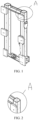
- the motor support apparatus 100 includes at least one beam structure 1.
- the beam structure 1 is formed by bending a metal plate.
- the metal plate includes a first long side and a second long side which are relative to each other.
- the bending includes bending the first long side towards the second long side and bending the second long side towards the first long side.
- the bent first long side is formed as a first free end side 11 of the beam structure 1
- the bent second long side is formed as a second free end side 12 of the beam structure 1, and a spacing is present between the first free end side 11 and the second free end side 12, in such a manner that a cross section of the beam structure 1 is in an unclosed shape.
- the motor support apparatus is configured as the at least one beam structure.
- the beam structure is a structure formed by bending two long sides of the rectangular metal plate relative to each other, and the structure formed by the bending is unclosed. Therefore, according to the beam structure of present disclosure, a bent edge may be adjusted depending on different motor axial heights. Therefore, a vertical height of the beam structure could be adjusted according to actual requirements, and an adjustable range of the height of the motor support apparatus is expanded, better satisfying mounting requirements of drive motors of different shaft heights, effectively improving universality of the motor support apparatus.
- the motor support apparatus is suitable for a plurality of motors having different shaft heights.
- the beam structure 1 is a U-shaped beam in a structural form, with a U-shaped cross section of the beam; and/or the beam structure 1 is formed as a semi-closed internal cavity structure 15 by bending, a support plate 2 being provided in the internal cavity structure 15.
- This is a preferred structural form of the beam structure of the present disclosure.
- a bent structure having a plurality of sections connected to each other is formed along a length direction of the beam structure 1 thereof; or a curved structure is formed along the length direction of the beam structure 1 thereof.
- these are two different preferred structural forms of the beam structure in the length direction.
- a first preferred structure form is the bent structure having the plurality of sections connected to each other.
- Such a bent structure is beneficial to form a fastening connection of straight sections at two ends to the motor separately, while a middle section is connected to a bottom of the motor support apparatus, such as a base plate or chassis. Therefore, according to a special configuration of the one beam structure, the connections to different components could be realized at different parts of the beam, which reduces materials and provides a more compact structure while achieving a fixing effect.
- a fastening connection may be formed between an end section of the beam structure and the motor, while a middle section is connected to the bottom of the motor support apparatus, such as the base plate or the chassis. Therefore, according to the special configuration of the one beam structure, the connections to different components could be realized at different parts of the beam, which reduces materials and provides a more compact structure while achieving the fixing effect.
- the bent structure 1 having the plurality of sections connected to each other includes a first straight section 1a, a second straight section 1b, and a third straight section 1c.
- the second straight section 1b is connected between the first straight section 1a and the third straight section 1c, in such a manner that the first straight section 1a, the second straight section 1b, and the third straight section 1c are sequentially connected.
- the first straight section 1a and the second straight section 1b form a bend at the junction thereof.
- the second straight section 1b and the third straight section 1c form a bend at the junction thereof.
- a fastening connection with the motor may be formed through the first straight section and the third straight section, and a fastening connection between the motor support apparatus and the base plate or the chassis is formed through the second straight section.
- the beam structures 1 includes a first beam 13 and a second beam 14.
- a second straight section of the first beam 13 is connected to a second straight section of the second beam 14.
- a first section of the first beam 13 extends away with respect to the second beam 14, and a third section of the first beam 13 extends away with respect to the second beam 14.
- a first section of the second beam 14 extends away with respect to the first beam 13, and a third section of the second beam 14 also extends away with respect to the first beam 13. That is, a motor support in an "X" shape is formed.
- the two multi-section bent beam structures which are arranged and connected to each other back-to-back and extends away with respect to each other, effectively reduce a quantity of the beam structures in use, effectively reduce the materials, reduce the costs, improve economical efficiency of products, and save space of the whole machine, while satisfying the condition of being permanently connected to the motor at four different positions.
- the X-shaped motor support of the present disclosure is preferentially applied in a single-stage centrifugal blower. There is only one size of the compressor element, while there are five shaft heights of the drive motor used in total.
- a motor mounting manner is a mounting manner with four bottom feet and a flange. For a motor with a same mounting size, the X-shaped motor support requires fewer materials than the rectangular support, which reduces the costs, improves the economical efficiency of products, and saves the space of the whole machine.
- the first beam 13 and the second beam 14 have a same structure and a same shape and they are connected to each other symmetrically; and/or the second straight section of the first beam 13 is permanently connected to the second straight section of the second beam 14.
- screw, welding, or bonding, etc. is used for the connection.
- It is a further preferred structural form of the first beam and the second beam of the present disclosure i.e., structures and shapes of the first beam and the second beam are set to be the same, which could provide a uniform support for the motor from four directions to prevent tilting of the motor.
- the fixed connection of two straight sections of the first beam and the second beam could enable the first beam and the second beam to be fixed into one piece through the middle sections, and the stability of the motor support apparatus is improved. It provides an effective and stable support when it is arranged at a bottom of the motor.
- a first reinforcing rib 31 is provided at the junction of the first straight section 1a and the second straight section 1b, and a shape of the first reinforcing rib 31 matches a shape of the bend at the junction of the first straight section 1a and the second straight section 1b; and/or a second reinforcing rib 32 is provided at a junction of the second straight section 1b and the third straight section 1c, and a shape of the second reinforcing rib 32 matches a shape of the bend at the junction of the second straight section 1b and the third straight section 1c.
- the first reinforcing rib 31 is arranged on a side of an opening of the unclosed shape of the beam structure 1, and has one end permanently connected to the first free end side 11 and another end permanently connected to the second free end side 12; and/or the second reinforcing rib 32 is arranged on a side of the opening of the unclosed shape of the beam structure 1, and has one end permanently connected to the first free end side 11 and another end permanently connected to the second free end side 12. Since the beam structure defines the opening of the unclosed shape on one side, a structural strength at that position may have a serious risk, and phenomena such as deformation or damage, etc. may occur under a pressure.
- the structural strength of the opening and the bending part could be effectively enhanced.
- the structural strength of the opening and the bending part could also be effectively enhanced.
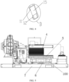
- the present disclosure further provides a motor assembly, which includes the motor support apparatus 100 according to any one of the above embodiments, and further includes a motor 4.
- the motor support apparatus 100 is connected to a bottom of the motor 4.
- the X-shaped motor support of the present disclosure is preferentially applied in the single-stage centrifugal blower. There is only one size of the compressor element of the product, and there are five shaft heights of the drive motor used in total.
- the motor mounting manner is a mounting manner with four bottom feet and a flange.
- a bracket of the X-shaped motor support of the present disclosure is composed of two main U-shaped beams. Each U-shaped beam is manufactured by performing a simple bending operation on a metal plate. Some reinforcing ribs/support plates are welded on the U-shaped beam to ensure strength and rigidity of the support structure for motor. Since an adjustable range of the U-shaped beam's height is wide, the mounting requirements of the drive motors having different shaft heights could be more easily satisfied. For the motor with the same mounting size, the X-shaped motor support requires fewer materials than the rectangular support, which reduces the costs, improves the economical efficiency of products, and saves the space of the whole machine.
- the bracket is composed of two main U-shaped beams.
- Each U-shaped beam is manufactured by performing a simple bending operation on a metal plate.
- some reinforcing ribs/support plates are welded on the U-shaped beam to ensure the strength and rigidity of the support structure for motor.
- a motor base plate 5 and a shock pad 6 are further included.
- the motor base plate 5 is mounted at a bottom of the motor support apparatus 100.
- At least one shock pad 6 is provided between the motor base plate 5 and the motor support apparatus 100. The shock pad could provide a shock absorption for the motor.
Landscapes
- Engineering & Computer Science (AREA)
- Power Engineering (AREA)
- General Engineering & Computer Science (AREA)
- Manufacturing & Machinery (AREA)
- Mechanical Engineering (AREA)
- Motor Or Generator Frames (AREA)
Applications Claiming Priority (2)
| Application Number | Priority Date | Filing Date | Title |
|---|---|---|---|
| CN202021077519.7U CN211958956U (zh) | 2020-06-11 | 2020-06-11 | 一种电机支撑装置和电机组件 |
| PCT/CN2021/099583 WO2021249524A1 (fr) | 2020-06-11 | 2021-06-11 | Dispositif de soutien de moteurs électriques et ensemble formant un moteur électrique |
Publications (2)
| Publication Number | Publication Date |
|---|---|
| EP4167445A1 true EP4167445A1 (fr) | 2023-04-19 |
| EP4167445A4 EP4167445A4 (fr) | 2024-07-17 |
Family
ID=73159305
Family Applications (1)
| Application Number | Title | Priority Date | Filing Date |
|---|---|---|---|
| EP21822768.4A Withdrawn EP4167445A4 (fr) | 2020-06-11 | 2021-06-11 | Dispositif de soutien de moteurs électriques et ensemble formant un moteur électrique |
Country Status (7)
| Country | Link |
|---|---|
| US (1) | US20240297550A1 (fr) |
| EP (1) | EP4167445A4 (fr) |
| JP (1) | JP7544869B2 (fr) |
| KR (1) | KR102779557B1 (fr) |
| CN (1) | CN211958956U (fr) |
| BR (1) | BR112022024945A2 (fr) |
| WO (1) | WO2021249524A1 (fr) |
Families Citing this family (2)
| Publication number | Priority date | Publication date | Assignee | Title |
|---|---|---|---|---|
| CN211958956U (zh) * | 2020-06-11 | 2020-11-17 | 阿特拉斯·科普柯(无锡)压缩机有限公司 | 一种电机支撑装置和电机组件 |
| CN115111662A (zh) * | 2021-03-19 | 2022-09-27 | 宁波奥克斯电气股份有限公司 | 一种电机支架及空调器 |
Family Cites Families (20)
| Publication number | Priority date | Publication date | Assignee | Title |
|---|---|---|---|---|
| US4253634A (en) * | 1978-09-05 | 1981-03-03 | Emerson Electric Co. | Electric motor mounting system |
| JPS5745256U (fr) * | 1980-08-28 | 1982-03-12 | ||
| JPH0434342Y2 (fr) * | 1987-07-31 | 1992-08-17 | ||
| US5561902A (en) | 1994-09-28 | 1996-10-08 | Cosma International Inc. | Method of manufacturing a ladder frame assembly for a motor vehicle |
| US5752688A (en) * | 1996-09-10 | 1998-05-19 | Emerson Electric Co. | Support assembly that is selectively repositionable and attachable to different sides of an air cooled machine housing |
| KR100606985B1 (ko) * | 1999-06-05 | 2006-07-31 | 오노 다쯔오 | 프레임과 이 프레임에 의해 조립되는 구조체 |
| CN2442442Y (zh) * | 2000-09-20 | 2001-08-08 | 上海通用风机股份有限公司 | 一种新型钢板电机导轨 |
| US6628027B2 (en) * | 2000-12-18 | 2003-09-30 | Siemens Westinghouse Power Corporation | Power generation system including an apparatus for attaching a generator stator core to frame support and associated methods |
| JP2004155219A (ja) * | 2002-11-01 | 2004-06-03 | Fuji Heavy Ind Ltd | 自動車の車体後部構造 |
| US6681489B1 (en) * | 2003-01-31 | 2004-01-27 | Metalsa Roanoke Inc | Method for manufacturing a vehicle frame assembly |
| US7210661B1 (en) * | 2005-10-14 | 2007-05-01 | Heatcraft Refrigeration Products, Llc | Motor installation system |
| US8226063B2 (en) * | 2006-10-23 | 2012-07-24 | Intier Automotive Inc | Power seat track drive assembly |
| CN202630327U (zh) * | 2012-06-27 | 2012-12-26 | 珠海格力电器股份有限公司 | 电机限位装置 |
| KR101332197B1 (ko) * | 2012-07-30 | 2013-11-25 | 금성제어기 주식회사 | 컨트롤 캐비닛용 골조 |
| CN106553696A (zh) * | 2016-10-31 | 2017-04-05 | 安徽江淮汽车集团股份有限公司 | 重型卡车车架总成 |
| JP2018165491A (ja) * | 2017-03-28 | 2018-10-25 | 株式会社荏原製作所 | 横軸ポンプ及び横軸ポンプ用ベース |
| CN210718024U (zh) * | 2019-09-18 | 2020-06-09 | 浙江国祥股份有限公司 | 一种风机电机组件 |
| CN210490638U (zh) * | 2019-10-12 | 2020-05-08 | 佛山市源绿品通风设备有限公司 | 一种电机座的纵向调整固定机构 |
| CN211958956U (zh) * | 2020-06-11 | 2020-11-17 | 阿特拉斯·科普柯(无锡)压缩机有限公司 | 一种电机支撑装置和电机组件 |
| KR102617477B1 (ko) * | 2021-07-09 | 2023-12-27 | 동양산전(주) | 배전반용 프레임 구조체 |
-
2020
- 2020-06-11 CN CN202021077519.7U patent/CN211958956U/zh active Active
-
2021
- 2021-06-11 KR KR1020237000431A patent/KR102779557B1/ko active Active
- 2021-06-11 BR BR112022024945A patent/BR112022024945A2/pt not_active Application Discontinuation
- 2021-06-11 WO PCT/CN2021/099583 patent/WO2021249524A1/fr not_active Ceased
- 2021-06-11 JP JP2022576066A patent/JP7544869B2/ja active Active
- 2021-06-11 US US18/009,122 patent/US20240297550A1/en not_active Abandoned
- 2021-06-11 EP EP21822768.4A patent/EP4167445A4/fr not_active Withdrawn
Also Published As
| Publication number | Publication date |
|---|---|
| EP4167445A4 (fr) | 2024-07-17 |
| JP2023528979A (ja) | 2023-07-06 |
| WO2021249524A1 (fr) | 2021-12-16 |
| JP7544869B2 (ja) | 2024-09-03 |
| BR112022024945A2 (pt) | 2022-12-27 |
| US20240297550A1 (en) | 2024-09-05 |
| CN211958956U (zh) | 2020-11-17 |
| KR20230019963A (ko) | 2023-02-09 |
| KR102779557B1 (ko) | 2025-03-10 |
Similar Documents
| Publication | Publication Date | Title |
|---|---|---|
| US20240297550A1 (en) | Motor support apparatus and motor assembly | |
| CN102141272A (zh) | 空气调节装置的室外单元 | |
| US20060213853A1 (en) | Relay rack | |
| JP2005140380A (ja) | 空気調和機の室外機 | |
| EP4458210A1 (fr) | Support de bureau réglable en hauteur ayant des structures de montage rapide, et bureau réglable en hauteur | |
| JP5911393B2 (ja) | 空気調和機室外ユニット | |
| CN215173512U (zh) | 一种用于显示屏的高强度支撑装置 | |
| CN224187777U (zh) | 耐冲击的防爆风机 | |
| CN213870417U (zh) | 风机支架 | |
| CN119737651B (zh) | 一种新型天花内机框架结构及空调器 | |
| CN217680602U (zh) | 机罩和车载泵 | |
| CN207865564U (zh) | 一种空调室外机 | |
| CN222885762U (zh) | 一种型材扭拧矫直装置 | |
| CN112283170A (zh) | 一种用于风机的安装支架 | |
| CN222160691U (zh) | 一种洗衣机三角支架及洗衣机 | |
| CN218523671U (zh) | 一种空调室外机及空调器 | |
| CN218177481U (zh) | 一种水泵支架 | |
| US2912195A (en) | Support structure for a blower housing | |
| CN223637234U (zh) | 一种力学试验装置 | |
| CN216842303U (zh) | 一种支架为焊接式的玻璃钢风机 | |
| CN213655195U (zh) | 一种可进行快速拆卸安装的工业大风扇 | |
| KR20250079652A (ko) | 더블파이프 형상의 모터 마운트 | |
| CN220582570U (zh) | 一种安装结构及空调室外机 | |
| CN215629405U (zh) | 可装配置式盖梁骨架拼装装置 | |
| CN215982908U (zh) | 一种电机的安装架以及空调 |
Legal Events
| Date | Code | Title | Description |
|---|---|---|---|
| STAA | Information on the status of an ep patent application or granted ep patent |
Free format text: STATUS: THE INTERNATIONAL PUBLICATION HAS BEEN MADE |
|
| PUAI | Public reference made under article 153(3) epc to a published international application that has entered the european phase |
Free format text: ORIGINAL CODE: 0009012 |
|
| STAA | Information on the status of an ep patent application or granted ep patent |
Free format text: STATUS: REQUEST FOR EXAMINATION WAS MADE |
|
| 17P | Request for examination filed |
Effective date: 20230105 |
|
| AK | Designated contracting states |
Kind code of ref document: A1 Designated state(s): AL AT BE BG CH CY CZ DE DK EE ES FI FR GB GR HR HU IE IS IT LI LT LU LV MC MK MT NL NO PL PT RO RS SE SI SK SM TR |
|
| R17P | Request for examination filed (corrected) |
Effective date: 20230105 |
|
| DAV | Request for validation of the european patent (deleted) | ||
| DAX | Request for extension of the european patent (deleted) | ||
| TPAC | Observations filed by third parties |
Free format text: ORIGINAL CODE: EPIDOSNTIPA |
|
| A4 | Supplementary search report drawn up and despatched |
Effective date: 20240619 |
|
| RIC1 | Information provided on ipc code assigned before grant |
Ipc: F16M 1/08 20060101ALN20240613BHEP Ipc: H02K 5/24 20060101ALI20240613BHEP Ipc: H02K 5/26 20060101AFI20240613BHEP |
|
| STAA | Information on the status of an ep patent application or granted ep patent |
Free format text: STATUS: EXAMINATION IS IN PROGRESS |
|
| 17Q | First examination report despatched |
Effective date: 20250409 |
|
| STAA | Information on the status of an ep patent application or granted ep patent |
Free format text: STATUS: THE APPLICATION IS DEEMED TO BE WITHDRAWN |
|
| 18D | Application deemed to be withdrawn |
Effective date: 20250812 |