EP4167794B1 - Oberer anschlag für reissverschlusskette und verfahren zum lösen des schiebers von dem reissverschluss - Google Patents
Oberer anschlag für reissverschlusskette und verfahren zum lösen des schiebers von dem reissverschluss Download PDFInfo
- Publication number
- EP4167794B1 EP4167794B1 EP21737741.5A EP21737741A EP4167794B1 EP 4167794 B1 EP4167794 B1 EP 4167794B1 EP 21737741 A EP21737741 A EP 21737741A EP 4167794 B1 EP4167794 B1 EP 4167794B1
- Authority
- EP
- European Patent Office
- Prior art keywords
- channel
- slider
- top stop
- outlet
- slide fastener
- Prior art date
- Legal status (The legal status is an assumption and is not a legal conclusion. Google has not performed a legal analysis and makes no representation as to the accuracy of the status listed.)
- Active
Links
Images




Classifications
-
- A—HUMAN NECESSITIES
- A44—HABERDASHERY; JEWELLERY
- A44B—BUTTONS, PINS, BUCKLES, SLIDE FASTENERS, OR THE LIKE
- A44B19/00—Slide fasteners
- A44B19/24—Details
- A44B19/36—Means for permanently uniting the stringers at the end; Means for stopping movement of slider at the end
-
- A—HUMAN NECESSITIES
- A44—HABERDASHERY; JEWELLERY
- A44B—BUTTONS, PINS, BUCKLES, SLIDE FASTENERS, OR THE LIKE
- A44B19/00—Slide fasteners
- A44B19/24—Details
- A44B19/38—Means at the end of stringer by which the slider can be freed from one stringer, e.g. stringers can be completely separated from each other
-
- A—HUMAN NECESSITIES
- A44—HABERDASHERY; JEWELLERY
- A44B—BUTTONS, PINS, BUCKLES, SLIDE FASTENERS, OR THE LIKE
- A44B19/00—Slide fasteners
- A44B19/24—Details
- A44B19/38—Means at the end of stringer by which the slider can be freed from one stringer, e.g. stringers can be completely separated from each other
- A44B19/384—Separable slide fasteners with quick opening devices
- A44B19/386—Top end stop means for quick opening slide fasteners
Definitions
- the present application relates to top stops for slide fastener chains and slide fastener chains including such top stops.
- the application also relates to methods of disengaging a slider from a slide fastener.
- Conventional slide fasteners include a pair of stringers and an opening and closing means commonly referred to as a slider.
- Each stringer includes a tape and a plurality of coupling elements.
- the coupling elements extend along a first edge of each tape and when the slider of the slide fastener has been moved to a closed position, corresponding coupling elements of the stringers interdigitate, couple or interlock.
- the separate portions of the article may be releasably joined by closing the slide fastener by moving the slider to the closed position, and thereby bringing the coupling elements into above interdigitating relationship.
- Slide fasteners are therefore both useful and versatile and are employed in a range of applications including garments, furnishings and luggage.
- Known slide fasteners are generally constructed as follows.
- a coupling portion is attached to a first edge of a tape to form a stringer.
- This first edge may be referred to as the coupling edge of the stringer.
- the tape can be woven or knitted and may be formed from, for example, polyester.
- the coupling elements may be attached to the tape by, for example, crimping or molding the coupling elements onto a reinforced edge of the tape.
- the reinforced end may include a cord, and the cord may be sewn or woven into the tape.
- the coupling elements may be formed as a continuous coil. In this case, the coupling elements are most commonly stitched to a surface of the tape at the edge of the tape or, alternatively, are woven or knitted into the tape.
- the chain is generally planar, and the chain (and the coupling elements which form part of the chain) extends along a longitudinal axis of the chain.
- a slider is mounted to the chain onto coupling elements of each respective stringer such that the slider can move along the chain between the two stringers.
- the slider commonly includes a main body having an upper and lower blade through which the coupling elements of each stringer pass.
- a pull tab or pull cord is attached to the main body which may be grasped by a user in order to effectively move the slider along the chain.
- the main body includes a guide post (sometimes referred to as a diamond) which, in part, defines a Y-shaped channel which is configured to carry coupling elements of the first and second stringers.
- the slider can include upper flanges and lower flanges which are disposed on each of the right and left side edge parts of the upper and lower blades, that is, the edges of the slider substantially parallel to a direction of operation of the slider.
- the flanges provided on the upper blade protrude downwards towards the lower blade and flanges provided on the lower blade protrude upwards towards the upper blade.
- the flanges are configured for sliding engagement with the coupling elements.
- Movement of the slider along the chain in a first sliding direction along an axis of operation of the slider causes the coupling elements of the first stringer to attach to the coupling elements of the second stringer.
- the slide fastener may be regarded as being in a fully closed configuration. Movement of the slider along the chain in a second sliding direction, along the axis of operation of the slider, opposite to the first sliding direction, causes the coupling elements of the first stringer to detach from the coupling elements of the second stringer.
- the slide fastener When the slider is no longer able to uncouple elements any further in the second sliding direction i.e. substantially all the coupling elements of the first stringer are detached from the coupling elements of the second stringer, the slide fastener may be regarded as being in a fully open configuration.
- the chain is cut to a desired length to form a desired length of slide fastener.
- Stops (often referred to as top stops and bottom stops) may be attached to either or both ends of the chain.
- the stops limit the extent of movement that the slider can undertake along the chain. It is usually the case that a top stop limits movement of the slider in the first sliding direction and a bottom stop limits movement of the slider in the second sliding direction.
- stops may be used in order to limit the movement of the slider along the chain.
- the slider is no longer able to couple or uncouple elements, or move, when the slider abuts on a stop of some variety, such as a bottom stop or a top stop.
- the top stop may be configured to abut on a top portion of the slider, for example a top edge of a flange provided on the slider main body, and may limit the travel of the slider in the first sliding direction.
- the bottom stop may be configured to abut on a bottom portion of the slider, for example a bottom edge of a flange provided on the main body of the slider, and may limit the travel of the slider in the second sliding direction. Stops may also be configured to abut on the upper or lower blades of the slider.
- Some slide fasteners may have a single bottom stop which is attached to both the first and second stringers.
- Other slide fasteners which may be referred to as separating slide fasteners, may have two separate bottom stops each attached to a corresponding each one of the stringers.
- the two bottom stops may take the respective forms of a retainer box and an insertion pin.
- the insertion pin can be inserted into the retainer box in order to interlink the first and second stringers with each other.
- the insertion pin can be removed from the retainer box when the slider is located adjacent the retainer box in order to pass through the slider and to separate the first and second stringers from each other.
- slide fasteners may have two separate top stops, each being attached to a corresponding one of the stringers. Other slide fasteners may have a single top stop attached to one or both of the stringers.
- Document CN 2 556 968 Y discloses a top stop according to the preamble of claim 1.
- the at least one top stop limits movement of the slider in the first sliding direction in order to prevent the slider from disengaging from the coupling elements and hence the slide fastener.
- the top stop may be formed on the tape prior to attachment of the slider.
- the top stop may be crimped or molded onto a reinforced edge of the tape.
- top stop which overcomes problems with known slide fasteners, whether discussed above or otherwise. It is also desirable to provide an alternative design of top stop.
- a top stop for a slide fastener according to claim 1.
- a top stop according to the present application allows for easy insertion of a slider onto the stringers of a slide fastener chain and prevents accidental detachment of the slider during use of the slide fastener.
- the top stop also facilitates the removal of the slider, should this be required, for example to replace a broken or faulty slider.
- the abutment protrusion is configured to restrict travel of the portion of the slider along the channel, when the portion of the slider is received in the channel and is translated from the outlet towards the inlet in order to release the slider from a stringer of the slide fastener.
- the abutment protrusion therefore provides a stop to prevent further travel of the slider along the channel, preventing accidental disengagement of the slider from the slide fastener.
- a distance between the abutment protrusion and the second side of the top stop in a direction perpendicular to the longitudinal axis of the top stop, may be selected such that when the portion of the slider is in contact with the abutment protrusion, the portion of the slider can be pivoted around a pivot point formed on the channel first side wall at the outlet of the channel.
- the abutment protrusion may define a release point for the portion of the slider.
- the distance determines force required to pivot the portion of the slider beyond the release point and through the abutment protrusion.
- the top stop may be tailored such that a minimum force is required to pivot the slider past the release point.
- the top stop may be tailored to provide for different specifications of the slide fastener, for example, in the case where quick and easy release of the slider is required, the distance between the release point and the outlet may be relatively short.
- the channel first side wall may extend at a constant incline from the inlet of the channel to the outlet. This may facilitate ease of entry for the slider to be translated from the inlet and through the channel and into sliding engagement with the row of coupling elements provided on the string fastener.
- the channel second side wall may include a second protruding portion defining an outlet protrusion adjacent the outlet of the channel.
- the outlet protrusion may be configured to prevent the portion of the slider from entering the outlet of the channel.
- the channel second side wall having the protruding portions provides a channel with varying widths.
- the channel width at the inlet and the outlet may be smaller than any channel width intermediate the outlet protrusion and the abutment protrusion.
- the channel width at the inlet may be larger than the channel width at the outlet.
- the top stop may further include a stop portion located above the outlet of the channel.
- the stop portion may be configured to limit travel of the slider along a chain of the slide fastener by abutment with the portion of the slider.
- the stop portion may be located beyond the outlet of the channel when the top stop is orientated for normal use. As such, the top stop may function to prevent the slider from disengaging from the chain during normal use of the slide fastener.
- a stringer of a slide fastener may include a tape having a first planar surface and a second planar surface with a coupling edge to which coupling elements are attached, and an outer edge which is opposite and parallel to the coupling edge.
- a slide fastener chain includes a first stringer having a row of first coupling elements attached to a coupling edge of the first stringer and a second stringer having a row of second coupling elements attached to a coupling edge of the second stringer.
- the first and second stringers are attached to and detached from each other by interdigitating and uncoupling of the rows of the first and second coupling elements. At least one of the first and second stringers is provided with the top stop according to the invention.
- the row of first and row of second coupling elements may be teeth coupling elements.
- the row of first and row of second coupling elements may be formed by respective coil members.
- the top stop may be attached to the coupling edge of at least one of the first and second stringers.
- the top stop may be located in line with the first or second coupling elements.
- the top stop may include an inner portion on an inner side of the coupling edge and an outer portion on an outer side of the coupling edge.
- the inlet of the channel may be located on the inner portion, and the outlet of the channel may be located on the outer portion.
- the first body portion of the top stop may be mounted on a first planar surface of at least one of the of the first and second stringers.
- the top stop may be provided for use with a stringer having coupling elements on one planar surface of the tape, for example a coiled fastener.
- the slider may normally include only a single pair of flanges extending from one of the upper or lower blades of the slider main body (e.g. corresponding to the side of the stringer from which the coil extends) to engage the coupling elements and accordingly, the top stop having a channel formed on the first body portion for mounting on the corresponding planar surface of the stringer having the coupling elements will be sufficient to allow the removal of the slider from the slide fastener chain.
- the top stop may further include a second body portion for mounting on a second planar surface of the at least one of the first and second stringers, and the second body portion includes a second channel substantially identical to the channel of the first body portion.
- the top stop may be provided for use with a stringer having coupling elements on or crimped or molded to both planar surfaces of the tape of the stringer, for example a stringer having teeth-like coupling elements.
- the slider may normally include two pairs of opposing flanges (one on each side of said slide fastener chain) to engage the coupling elements.
- the top stop having a channel formed in first and second body portions which may be mounted on opposing planar surfaces of the tape of the stringer will allow opposing flanges of the slider to be translated through the top stop on each side of the slide fastener, facilitating ease of removal.
- the second body portion may include a second channel having an inlet and an outlet, a channel first side wall and a channel second side wall.
- the distance between the channel first and second side walls defines a channel width
- the channel width of the second channel may be substantially constant.
- the channel width may be sufficient to allow a flange of a slider to be translated through the channel.
- a top stop having a channel with protruding portions on a first body portion, and a constant width channel on a second body portion may facilitate ease of removal of a slider having two pairs of opposed flanges as the slider only needs to rotate through a single abutment protrusion provided on one face.
- the channel second side wall may include an incline from the inlet of the channel to the abutment protrusion having a constant angle relative to the longitudinal axis of the top stop from the inlet of the channel to the abutment protrusion.
- the channel may therefore function as guide to direct the flange of the slider through the channel and the slider into sliding engagement with adjacent coupling elements.
- the channel second side wall may include a first incline and a second incline.
- the first incline extends from the inlet to the second incline at a first angle relative to the longitudinal axis of the top stop.
- the second incline extends between the first incline and the abutment protrusion at a second angle relative to the longitudinal axis of the top stop.
- the second angle is less than the first angle. This may provide an additional barrier to prevent accidental disengagement of a slider from the slide fastener chain because the narrow width and shallow angle of the second incline of the channel second side wall will require further deliberate manipulation to allow the slider to pass through this second portion to allow subsequent release from the slider fastener chain.
- the inlet of the channel may be provided with a recess. This may make it easier for a user to insert a flange of the slider into the channel. This may also facilitate formation of the top stop onto the coupling edge of the stringer.
- the top stop may be molded by injection onto the coupling edge of at least one of the first and second stringers.
- the channel bottom surface may be formed by the stringer to which the top stop is attached.
- the first or second or both body portions may include two distinct sections which are separated by the channel width, thereby forming the channel in between the sections.
- the bottom surface of the channel may include the same material as the top stop.
- the first or second or both body portions may include a singular component having the channel formed in the first or second or both body portions, respectively.
- the top stop may be formed from any suitable material, for example, the top stop may include a polymer material such as polyester, polyacetal, or polyethylene, or the top stop may be metal based, such as aluminium, nickel or the like.
- the slide fastener may include a slide fastener chain according to the previous aspect, and a slider configured to be mounted to the first and second stringers to provide for selectively interdigitating and uncoupling of the first and second coupling elements.
- an article including a slide fastener.
- the slide fastener includes: a first stringer having first coupling elements and a second stringer having second coupling elements, and a slider configured to be mounted to the first and second stringers to provide for selectively interdigitating and uncoupling of the first and second coupling elements.
- the first stringer includes a first tape and the second stringer includes a second tape; and the first tape is attached to a first portion of the article and the second tape is attached to a second portion of the article. At least one of the first and second stringers is provided with a top stop according to the previously described aspects.
- the method may further include rotating the slider such that the portion of the slider can rotate through an outlet protrusion provided on the second side wall adjacent the outlet of the channel.
- FIG. 1 shows a slide fastener 10.
- the slide fastener 10 includes a slider 20 and a pair of stringers 12a, 12b.
- Each stringer includes a coupling portion in the form of a row of coupling elements 14a, 14b which are attached to an edge of a tape of each stringer.
- the edge to which the coupling elements are attached may be referred to as the coupling edge 16.
- the tape may be woven or knitted and may be formed from, for example, synthetic fibres such as polyester, vinylon or polyurethane and/or natural fibres such as cotton.
- the coupling elements 14a, 14b may be molded, as shown in FIG. 1 , or crimped teeth (not shown) or as a continuous coil with coil elements forming the coupling elements (not shown).
- the tape of the stringer 12a, 12b may be provided with a reinforced edge including a cord 16a (shown in FIG. 2 ), onto which the coupling elements 14a, 14b are attached.
- a reinforced edge including a cord 16a (shown in FIG. 2 ), onto which the coupling elements 14a, 14b are attached.
- the presence of the reinforced edge on the stringer 12a is optional.
- the tape of each stringer includes a first planar surface and a second planar surface opposite to the first planar surface.
- the first planar surface and the second planar surface join at the coupling edge 16 including the coupling elements 14a, 14b and the cord 16a to which they are attached so that the coupling elements 14a, 14b encompass the coupling edge 16 of both the first planar surface and the second planar surface.
- the coupling elements 14a, 14b include a head potion 14c in which is provided an engagement member which allows engagement with a head portion 14c of an opposing coupling element of a cooperating stringer.
- the tape also includes an outer edge which is opposite and parallel to the coupling edge 16.
- the two stringers 12a, 12b are brought together, such that the row of coupling elements 14a, 14b of each stringer 12a, 12b can attach to each other, by interdigitating.
- the slide fastener chain 18 includes the two stringers 12a, 12b and extends along a longitudinal axis A of the slide fastener 10. This axis is also known as the axis of operation.
- the slider 20 is attached to the slide fastener chain 18 such that the slider 20 can move along the rows of coupling element between the two stringers 12a, 12b.
- the slider 20 includes a slider body 21.
- the slider body 21 of the embodiment has an upper blade 23, a lower blade (not shown) disposed separately to be parallel to the upper blade 23, a guide post 26 connecting front end parts of the upper blade 23 and the lower blade.
- Upper flanges 24a, 24b and lower flanges (not shown) are disposed on each of the right and left side edge parts of the upper 21 and lower blades, that is, the edges of the slider substantially parallel to the direction of operation of the slider.
- a pull tab 25 is disposed on an upper surface of the upper blade 23 via a bridge portion 22. This pull tab 25 may be grasped by a user in order to effectively move the slider 20 along the rows of coupling elements.
- right and left shoulder mouths 21a, 21b are formed interposing the guide post 26, and a rear mouth 21c is formed at a rear end of the slider body 21.
- the guide post 26 communicates the right and left shoulder mouths 21a, 21b and the rear mouth 21c, and a substantially Y-shaped channel is formed within the slider 20 and between the blades.
- the row of coupling elements 14a of the first stringer 12a passes through the right shoulder mouth 21a and along the portion of the Y-shaped channel extending from the right shoulder mouth 21a until coming into releasably coupling contact with the row of coupling elements 14b of the second stringer 12b.
- the row of coupling elements on the second stringer 12b passes along the portion of the Y shaped channel extending from the left shoulder mouth 21b when entering the portion of the Y shaped channel extending from the rear mouth. It can be understood that only one row of coupling elements may be inserted into the slider 20 then the slider 20 may be able to travel along the row of coupling elements in the engaging and disengaging directions.
- flanges may only extend from either the upper blade or the lower blade.
- FIG. 9A to 9D show an example top stop according to the present application which would be appropriate for such a slider.
- Movement of the slider 20 along the rows of coupling elements 14a, 14b in a first sliding direction E causes the coupling elements 14a of the first stringer 12a to attach to the coupling elements 14b of the second stringer 12b. Movement of the slider along the chain in a second sliding direction D, opposite to the first sliding direction E, causes the coupling elements 14a of the first stringer 12a to detach from the coupling elements 14b of the second stringer 12b.
- Attached coupling elements are also known as coupled coupling elements, engaged coupling elements or paired coupling elements.
- the process of attaching coupling elements is also known as coupling, engaging or pairing.
- Top stops 30 and 40 are provided at the top end 18a of the coupling elements rows 14a, 14b. In this example, a different top stop is provided at the top end of each row of coupling elements 14a, 14b. However, it can be understood that in some cases only a single top stop 30 may be required (i.e. as part of only one of the stringers), and/or that each top stop 30, 40 may be identical.
- the top stops may be formed from any suitable material, for example, they may include a polymer material such as polyester, polyacethal, or polyethylene, or they may be metal based, such as aluminium, nickel or the like.
- a retainer box 11 is provided at the bottom end 18b of the row of coupling elements 14a, 14b, on the opposite side of the row to the top end 18a of the row of coupling elements 14a, 14b, into which an insertion pin 15 can be inserted in order to interlink the first and second stringers 12a, 12b.
- a box pin 13 provided on stringer 12a may be permanently fixed into the retainer box, therefore insertion pin 15 may be removed from the retainer box 11 when the slider 20 is located adjacent the retainer box 11, in order to pass through the slider 20 and separate the first and second stringers 12a, 12b from each other.
- the stringers 12a, 12b can therefore be separated.
- Slide fastener 10 is therefore an example of an open ended string fastener 10.
- top stop 30 and top stops 130, 230 and 330 as described later according to the present application may have applicability in all types of slide fastener and are not limited to the example shown in accompanying drawings.
- top stop 30 attached to the coupling edge 16 including a cord 16a (or reinforced edge) of stringer 12a, is shown in FIG. 2 .
- the top stop may be attached directly to the coupling edge of the tape.
- top stop 30 is integrally injected onto the fastener tape by injection molding.
- the top stop 30 as with the coupling elements 14a 14b is similarly fixed to the coupling edge 16 of the tape encompassing the first planar surface and the second planar surface with an extension extending towards the outer edge 17 of the tape of the stringer 12a.
- the top stop 30 has a first body portion 31a on the side of the first planar surface ( FIG. 3A ) and a second body portion 31b on the side of the second planar surface ( FIG. 3B ). That is, the top stop includes two body portions mounted on opposing planar surfaces of the tape of the stringer 12a, 12b.
- the top stop 30 may be formed as a singular component around the tape, for example, the first and second body portions 31a, 31b may be integrally formed around the tape. Alternatively, they may be distinct body portions which are joined together around the tape. Side views of the top stop are shown in FIGS. 3C and 3D. The body portions meet, or join, or converge around the coupling edge of the tape such that the inlets 32 of channels 36 are provided at the coupling edge 16 of the tape (FIG. 3C), and the outlets 34 of the channels 36 are provided more proximate to the outer edge 17 of the tape (FIG. 3D).
- the top stop 30 can be provided with a groove to receive the fastener tape. In some examples, top stop 30 is substantially rectangular.
- the top stop 30 is provided with a stop portion 33.
- the stop portion 33 limits the movement of the slider 20 in the first direction E.
- the stop portion 33 preferably extends in a direction perpendicular to the axis of operation so that when approached by the slider 20, a part of the slider body 21, for example a flange 24a comes into contact with the stop portion 33.
- the stop portion 33 is located distally (relative to the rest of the top stop) from the coupling edge of the stringer 12a and is located above a channel 36 in the first sliding direction E.
- the channel 36 is provided in the top stop 30 to facilitate removal of the slider 20 from the stringer 12a.
- the stop portion 33 protrudes from the first and second body portions 31a, 31b of the top stop 30 toward the outer edge 17 of the tape.
- the stop portion 33 may be included within at least one of the first and second body portions 31a, 31b of the top stop 30.
- Top stop 30 includes a channel 36 having an inlet 32 and an outlet 34, and a channel bottom surface 35.
- the channel 36 is configured to receive a portion of the slider, for example a flange 24a provided on the slider 20.
- the channel 36 is configured to allow for easy insertion of the slider onto the stringer 12a, 12b, for example to the stringer 12a on which the retainer box 11 and the box pin 13 are attached.
- the top stop 30 will prevent movement of the slider 20 in the first sliding direction E beyond the row of coupling elements 14a and the box pin 13 (or the retainer box 11 or both) will prevent movement of the slider 20 beyond the row of coupling elements 14a in the second sliding direction D, thus ensuring that the slider 20 does not accidentally come away from the row of coupling elements 14a.
- the channel 36 is also configured to facilitate the removal of the slider 20, should this be required, for example to replace a broken or faulty slider.
- the inlet 32 to the channel 36 is formed at the side of the top stop 30 at the coupling edge 16 of the tape of the stringer 12a.
- the inlet 32 of the channel may optionally be provided with a recess 32a.
- the outlet 34 is formed at the side of the top stop 30 proximal to the outer edge 17 of the tape and is located below the stop portion 33. That is, the outlet 34 is positioned between the end of the row of coupling elements proximate to the top stop 30 and the stop portion 33 of the top stop 30.
- the outlet 34 is located closer to the top end 18a of the coupling elements row 14a than the inlet 32.
- the inlet 32 is the mouth of the top stop 30 through which a slider 20 may enter the channel 36 in order for the slider 20 to be inserted onto the slide fastener chain 18 and the outlet 34 is the mouth of the top stop 30 from which a slider 20 may exit the channel 36 of the top stop 30 in order to slide onto the row of coupling elements 14a to complete the insertion.
- the inlet 32 and outlet 34 function in the opposite manner. However for consistency, the meaning of these terms will remain static and not change depending on the direction of movement of the slider 20.
- Channel 36 includes a channel first side wall 38 and a channel second side wall 37 and a channel bottom surface 35.
- the channel first side wall 38 is disposed more proximate to the row of coupling elements of the stringer 12a than the channel second side wall 37.
- the channel first side wall 38 and the channel second side wall 37 are opposed to each other, the channel bottom surface 35 of the channel 36 includes a flat surface, and connects the channel first side wall 38 and the channel second side wall 37. That is, a groove extending from the inlet 32 to the outlet 34 is formed as the channel 36.
- the channel bottom surface 35 may include the tape 12a.
- the first, or second, or both body portions 31a, 31b may include two distinct sections which are separated by a channel width, thereby forming the channel 36 (or valley) in between the sections.
- a channel (or valley) bottom surface 35 may include (or be defined in part by) the fastener tape 12a.
- the channel bottom surface 35 may include the same material as the top stop.
- the first, or second, or both body portions 31a, 31b may include a singular component having a channel 36 formed in body portion.
- the channel first side wall 38 has a substantially flat or straight profile and extends at constant incline down from the inlet 32 of the channel to the outlet 34.
- the channel second side wall 37 includes a stepped profile to provide the channel 36 with varying widths across the length of the channel 36.
- the channel width at any point along the channel is defined as the distance parallel to the longitudinal axis of the top stop between the channel first and second side walls. In normal use, the longitudinal axis of the top stop is brought parallel to the axis of operation (A) (or longitudinal axis) of the slide fastener.
- the width of the channel 36 at the inlet 32 is denoted by letter F.
- the channel second side wall 37 extends at an incline from the inlet 32, narrowing the width of the channel to an end point 37b of an abutment protrusion 37a.
- the channel width extending from the abutment protrusion 37a at the end point 37b to the channel first side wall 38 is denoted by letter G.
- This end point 37b may also be defined as the release point for a flange 24a of the slider received in the channel 36 during the operation to release a slider 20 from the row of coupling elements 14a.
- the channel second side wall 37 then extends away from the channel first side wall, widening the channel 36, to form the abutment protrusion 37a.
- the channel width at this point is denoted by letter H.
- the channel second side wall 37 includes another protruding portion where the channel second side wall 37 extends towards the channel first side wall 38 and out again to form an outlet protrusion 39 at the outlet 34.
- the channel width 36 at this point is denoted by letter J.
- the top stop 30 of this example is therefore provided with two stepped regions, one adjacent the outlet in the form of the outlet protrusion 39 and another in the form of the abutment protrusion 37a.
- the channel width of the channel 36 at the end point 37b of the abutment protrusion 37a, the release point, G is less than the channel width of the inlet 32 and also the channel width of the outlet (F > G, J > G).
- the channel width H of the channel 36 intermediate the abutment protrusion 37a and the outlet protrusion 39 is greater than the channel width J at the outlet 34 and the width G at the end point 37b of the abutment protrusion 37a (H>J>G).
- the channel width G of the channel 36 at the end point 37b of the abutment protrusion has a minimum width in the width of the channel 36, and this channel width G is greater than the thickness of the flange 24a.
- the channel width at the inlet 32 may be smaller than the channel width H of the channel 36 intermediate the abutment protrusion 37a and the outlet protrusion 39.
- the channel width F at the inlet 32 may be larger than the channel width J at the outlet 34.
- the distance between the end of the row of coupling elements 14a proximate to the top stop 30 and the outlet 34 is less than the distance between the end of the row of coupling elements 14a proximate to the top stop 30 and the inlet 32, in consequence the channel first side wall 38 of the channel 36 inclines away from the axis of operation A of the slide fastener by an angle of less than 90 degrees.
- the channel second side wall 37 has at least three flat surfaces.
- a first flat surface is formed between the inlet 32 and the end point 37b of the abutment protrusion 37a, and inclines with respect to the second direction D. This inclination may be more acute than that of the channel first side wall or it may be the same. In other embodiments, it may be less acute.
- a second flat surface is formed between the end point 37b of the abutment protrusion 37a and the base (root) of the outlet protrusion 39.
- a third flat surface is formed between the base of the outlet protrusion 39 and an end point 39a of the outlet protrusion 39 or in embodiments which do not have an outlet protrusion, the outlet 34.
- the channel is provided on both the first and second body portions 31a, 31b of the top stop 30. Accordingly, there are two inlets 32 at the coupling edge 16, and two outlets 34 at the side of the top stop proximal to the outer edge 17 of the tape, allowing for passage of an upper and lower flange 24a provided on the slider.
- the flange protruding from the upper blade 23 of slider 20 can enter inlet 32 provided on the first body portion 31a of the top stop 30, and the flange protruding from the lower blade of the slider 20 can enter inlet 32 provided on the second body portion 31b of the top stop 30.
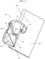
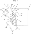
- the slider 20 can be mounted to the stringer of the slide fastener as shown in FIG. 4 .
- the upper blade 23 of the slider 20 has been removed to allow views of the flanges 24a, 24b and guide post 26.
- the width 27 of flange 24a may be defined as the distance by which the flange 24a extends normally to the right side edge of the upper blade 23 (or left side edge of flange 24b).
- the length of the flange 24a may be defined as the distance by which the flange 24a extends parallel to the right side edge (or left side edge of flange 24b).
- the width 27 of flange 24a is marked in two locations along the flange 24a.
- the width 27 of the flange 24a is constant across the length of the flange 24a.
- the flange 24a or flanges 24a, 24b may be provided with different widths at different locations along the length of the flange 24a or flanges 24a, 24b.
- Flange 24a enters the channel 36 at the inlet 32.
- the channel width along the length of the channel 36 is always wider than the width of the flange 24a.
- the thickness between the channel bottom surfaces 35 of each channel 36 provided on the first and second body portions 31a, 31b of the top stop 30 is narrower than the gap between the flange 24a of the upper blade 23 and the flange of the lower blade, as such, the slider 20 can pass through the top stop 30.
- the tape of the stringer 12a may be manipulated, for example by flexing, and or folding the tape material, and the slider may be pulled via the pull tab 25 such that the flange 24a is translated through the channel 36 out of the outlet 34 and into sliding engagement with the coupling elements adjacent the top stop 30.
- a lower flange provided on the lower blade of the slider 20 may translate through the channel 36 provided on the second body portion 31b of the top stop 30.
- the slider 20 may then be moved in the second sliding direction D down the row of elements 14a so that the insertion pin 15 can be used to position the row of coupling elements 14b of the second stringer 12b and allow operation of the slide fastener.
- the slider 20 In normal use, the slider 20 is pulled in the first direction E to interdigitate the coupling elements 14a, 14b and at the end of the slider's intended travel (the end of the slide fastener), the leading end of flange 24a of slider 20 will abut on the stop portion 33, preventing further travel of the slider 20.
- the flange 24a of slider 20 In the event that some misalignment of the slider 20 occurs, for example by the application of force in a direction other than the first direction E or second direction D, the flange 24a of slider 20 will abut on outlet protrusion 39 of channel 36, preventing the leading end of flange 24a from entering the channel 36 at the outlet 34. Accordingly, the outlet protrusion 39 can prevent accidental disengagement of the slider from the remaining slide fastener during normal operation.
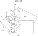
- the slider 20 can be intentionally removed from the slide fastener as shown in FIGS. 5A and 5B .
- the tape of the stringer 12a is manipulated and the slider is twisted to allow flange 24a of slider 20 to enter the outlet 34 of the channel 36 formed in top stop 30.
- Manipulation, in the form of folding or flexing of the tape material for example folding a portion of the tape back on itself, or flexing in a direction at an angle to the axis of operation A, allows the flange 24a to bypass the outlet protrusion 39, and enter the channel 36.
- Such flexing of the tape material may be flexing in the plane of the tape.
- abutment protrusion 37a can provide a further stop to prevent accidental disengagement of the slider.
- the slider 20 can then be pivoted around pivot point P. Therefore the flange 24a can translate through the release point of the abutment protrusion 37a ( FIG. 5B ) allowing the slider 20 to be disengaged from the slide fastener.
- Pivoting the slider 20 around pivot point P rotates the guide post 26 bringing it into contact with the uppermost coupling element 14a of the stringer 12a.
- the guide post 26 pushes against the coupling element 14a at point R bringing the coupling element 14a into contact with the flange 24a at point Q.
- a reaction force from the tape via the coupling element 14a is also exerted on the guide post 26.
- the force applied to pivot the slider 20 around pivot point P has to be greater than the reaction force at point R from the coupling element 14a on the guide post 26.
- the slider may be rotated in an anticlockwise direction but it can be understood that the rotation may be dependent upon the orientation of the top stop and the slider on the stringer.
- the amount of force required to pivot the flange 24a will be dependent upon the distance perpendicular to the longitudinal axis from the outlet 34 to the release point of the abutment protrusion 37a. This distance determines the degree to which the coupling element 14a needs to move from its normal axis in order to allow the flange 24a to travel and pass the abutment protrusion 37a, that is, against the reaction force applied to the guide post 26. The greater this distance, the more the coupling element 14a and tape need to be deflected, resulting in a greater reaction force on the guide post 26 and hence a greater force to pivot the flange 24a will be required. As such, the top stop may be tailored to require a minimum force in order to disengage a slider from the slide fastener.
- top stop 130 is shown in FIGS. 6 and 7 .
- Top stop 130 is shown in perspective view in FIG. 6.
- the features of the top stop 130 which are the same as the previous example are denoted with the like reference numerals incremented by 100 and are not described again for brevity.
- the channel 136 of top stop 130 is also provided with protruding portions.
- the channel second side wall 137 includes a first incline 140 starting at the inlet 132 and extending to a second incline 142, the first incline 140 having a first angle ⁇ relative to the longitudinal axis A of the top stop 130, with respect to the second direction D.
- This first incline 140 extends to the second incline 142, the second incline having a second angle ⁇ relative to the longitudinal axis A of the top stop with respect to the second direction D.
- both the first angle ⁇ and second angle ⁇ are obtuse angles (although this may not always be the case) and, the second angle ⁇ is less (or less obtuse) than the first angle ⁇ of the first incline 140.
- the channel second side wall 137 then extends away from the channel first side wall 138 forming the abutment protrusion 137a.
- the distance K perpendicular to the longitudinal axis of the top stop between release point 137b of the abutment protrusion 137a and the outlet 134 is larger than the width of the flanges of the slider, and accordingly, a greater force is required to pivot the slider through the release point.
- the top stop 130 also includes an outlet protrusion 139 which is formed by the channel second side wall 137 extending towards the channel first side wall 138 and then away from again at the outlet 134 of channel 136.
- top stop 230 is illustrated in FIGS. 8A and 8B .
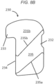
- Top stop 230 is formed around the coupling edge of the stringer 12a or 12b and includes a first body portion 231a ( FIG. 8A ) and second body portion 231b ( FIG. 8B ), one positioned on each planar surface of the tape of the stringer 12a or 12b.
- First body portion 231a is provided with a channel 236 having an abutment protrusion 237a and an outlet protrusion 239.
- the protrusions 237a, 239 are shown to be the same as channel 36 in top stop 30 but it can be understood that the channel 236 may be the same as channel 136 of top stop 130, both of which are described above.
- the second body portion 231b is also provided with a channel 235, and the channel 235 has a substantially constant channel width. That is, the channel first side wall 235a and the channel second side wall 235b incline against the longitudinal axis and each have substantially a flat surface.
- Sliders configured to couple teeth coupling elements have upper and lower flanges provided on either side of the slider 20 to engage teeth 14a.
- Top stop 230 is provided with two channels to allow insertion and removal of such a slider, and the upper and lower flanges will interact with first and second channels of the top stop respectively.
- the force required to release the slider 20 will be less because there is only one abutment protrusion 237a to overcome.
- top stop 330 is illustrated in FIGS. 9A to 9D. Unless otherwise specified, the features of the top stop 330 which are the same as the previous example are denoted with the like reference numerals incremented by 300 and are not described again for brevity.
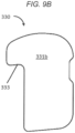
- Top stop 330 is formed around the coupling edge 16 of the stringer 12a or 12b and includes a first body portion 331a (FIG. 9A) and second body portion 331b ( FIG. 9B ), one positioned on either side of the stringer 12a or 12b.
- First body portion 331a is provided with a channel 336 substantially identical to channels 36, 236 described above. It can be understood that the channel may be formed according to channel 136, also described above.
- the second body portion 331b has a level surface, with no channel.
- Top stop 330 may be particularly suited for use with slide fasteners having coupling elements in the form of a continuous coil, because the coiled coupling elements are only present on a single planar surface of the tape 12a, 12b. As such, the slider will only have flanges on the upper blade or the lower blade of the slider to encourage engagement of the coupling elements on said one planar surface of the tape, thus requiring only a single channel in the top stop to facilitate the slider passing through the top stop in the same manner as already described.
- the top stop 330 may be provided with a single body portion for positioning on the planar surface of the stringer to which the coil coupling elements are attached. The single body portion may include a channel as described in the previous examples. In such an embodiment there is no second body portion on the planar surface of the stringer to which the coil coupling elements are not attached.
- top stops according to the present application on a moveable slide fastener with two sliders.
- both sliders on the stringer can make use of the top stop and be attached to or removed from the stringer.
Landscapes
- Slide Fasteners (AREA)
Claims (16)
- Oberer Anschlag (30, 130, 230, 330) für einen Reißverschluss (10), umfassend:einen ersten Körperabschnitt (31a, 131a, 231a, 331a), der einen Kanal (36, 136, 236, 336) mit einem Einlass (32, 132, 232, 332) an einer ersten Seite des oberen Anschlags (30, 130, 230, 330) und einem Auslass (34, 134, 234, 334) an einer zweiten Seite des oberen Anschlags (30, 130, 230, 330) aufweist, wobei die zweite Seite gegenüber der ersten Seite liegt,wobei der Kanal (36, 136, 236, 336) so konfiguriert ist, dass er einen Abschnitt (24a) eines Schiebers (20) des Reißverschlusses (10) aufnimmt, wobei der Kanal (36, 136, 236, 336) durch eine erste Kanalseitenwand (38, 138, 238, 338) und eine zweite Kanalseitenwand (37, 137, 237, 337) sowie eine dazwischenliegende Kanalbodenfläche (35) definiert ist,dadurch gekennzeichnet, dassdie zweite Kanalseitenwand (37, 137, 237, 337) einen vorstehenden Abschnitt umfasst, der einen Anlagevorsprung (37a, 137a, 237a, 337a) in dem Kanal (36, 136, 236, 336) definiert,der obere Anschlag (30, 130, 230, 330) eine längliche Achse umfasst, die parallel zu einer Betätigungsachse (A) des Schiebers (20) ist, und ein Abstand parallel zu der Längsachse des oberen Anschlags (30, 130, 230, 330) zwischen der ersten Kanalseitenwand (38, 138, 238, 338) und der zweiten Kanalseitenwand (37, 137, 237, 337) eine Kanalbreite definiert,die sich von dem Anlagevorsprung (37a, 137a, 237a, 337a) zu der ersten Kanalseitenwand (38, 138, 238, 338) erstreckende Kanalbreite (G) kleiner ist als die Kanalbreite (F) am Einlass (32) und die Kanalbreite (J) am Auslass, undder Anlagevorsprung (37a, 137a, 237a, 337a) so konfiguriert ist, dass er die Bewegung des Abschnitts (24a) des Schiebers entlang des Kanals (36, 136, 236, 336) begrenzt, wenn der Abschnitt des Schiebers (20) in dem Kanal (36, 136, 236, 336) aufgenommen wird und von dem Auslass (34, 134, 234, 334) in Richtung des Einlasses (32, 132, 232, 332) verschoben wird, um den Schieber (20) von einem Tragband (12a) des Reißverschlusses (10) freizugeben.
- Oberer Anschlag (30, 130, 230, 330) nach Anspruch 1,wobei ein Abstand (K) zwischen dem Anlagevorsprung (37a, 137a, 237a, 337a) und der zweiten Seite des oberen Anschlags (30) in einer Richtung senkrecht zur Längsachse des oberen Anschlags so gewählt ist, dass, wenn der Abschnitt (24a) des Schiebers (20) in Kontakt mit dem Anlagevorsprung (37a) ist, der Abschnitt (24a) des Schiebers (20) um einen Schwenkpunkt (P) geschwenkt werden kann, der an der ersten Kanalseitenwand (38, 138, 238, 338) am Auslass (34, 134, 234, 334) des Kanals (36, 136, 236, 336) gebildet ist,wobei der Anlagevorsprung (37a, 137a, 237a, 337a) einen Freigabepunkt (37b, 137b) für den Abschnitt (24a) des Schiebers (20) definiert, undwobei der Abstand (K) die Kraft bestimmt, die erforderlich ist, um den Abschnitt (24b) des Schiebers (20) über den Freigabepunkt (37b, 137b) hinaus und durch den Anlagevorsprung (37a, 137a, 237a, 337a) zu schwenken.
- Oberer Anschlag (30, 130, 230, 330) nach Anspruch 1 oder 2, wobei sich die erste Kanalseitenwand (38, 138, 238, 338) mit einer konstanten Steigung vom Einlass (32, 132, 232, 332) des Kanals zum Auslass (34, 134, 234, 334) erstreckt.
- Oberer Anschlag (30, 130, 230, 330) nach einem der Ansprüche 1 bis 3,wobei die zweite Kanalseitenwand (37, 137, 237, 337) einen zweiten vorstehenden Abschnitt umfasst, der einen Auslassvorsprung (39, 139, 239, 339) neben dem Auslass (34, 134, 234, 334) des Kanals (36) definiert, undwobei der Auslassvorsprung (39, 139, 239, 339) konfiguriert ist, um zu verhindern, dass der Abschnitt (24a) des Schiebers (20) in den Auslass (34, 134, 234, 334) des Kanals (36, 136, 236, 336) eintritt.
- Oberer Anschlag (30, 130, 230, 330) nach Anspruch 4, wobei die Kanalbreite am Einlass (32, 132, 232, 332) und am Auslass (34, 134, 234, 334) kleiner ist als jede Kanalbreite (H) zwischen dem Auslassvorsprung (39, 139, 239, 339) und dem Anlagevorsprung (37a, 137a, 237a, 337a).
- Oberer Anschlag (30, 130, 230, 330) nach einem der Ansprüche 1 bis 5, wobei die Kanalbreite (F) am Einlass (32, 132, 232, 332) größer ist als die Kanalbreite (J) am Auslass (34, 134, 234, 334).
- Oberer Anschlag (30, 130, 230, 330) nach einem der Ansprüche 1 bis 6, der ferner einen oberhalb des Auslasses (34, 134, 234, 334) des Kanals angeordneten Anschlagabschnitt (33, 133, 233, 333) umfasst, wobei der Anschlagabschnitt (33, 133, 233, 333) so konfiguriert ist, dass er die Bewegung des Schiebers (20) entlang einer Reißverschlusskette (10) durch Anstoßen an den Abschnitt des Schiebers (20) begrenzt.
- Reißverschlusskette (18), umfassend:ein erstes Tragband (12a), das eine Reihe von ersten Kuppelgliedern (14a) aufweist, die an einer Kupplungskante (16) des ersten Tragbandes (12a) angebracht sind; undein zweites Tragband (12b), das eine Reihe von zweiten Kuppelgliedern (14b) aufweist, die an einer Kupplungskante (16) des zweiten Tragbands (12b) angebracht sind,wobei das erste und das zweite Tragband (12a, 12b) aneinander angebracht und voneinander getrennt werden, indem die Reihen von ersten und zweiten Kuppelgliedern (14a, 14b) miteinander gekoppelt und voneinander entkoppelt werden, undwobei das erste und/oder das zweite Tragband (12a, 12b) mit dem oberen Anschlag (30, 130, 230, 330) nach einem der Ansprüche 1 bis 7 versehen ist.
- Reißverschlusskette (18) nach Anspruch 8,wobei der obere Anschlag (30, 130, 230, 330) an der Kupplungskante (16) des ersten und/oder des zweiten Tragbandes (12a, 12b) angebracht ist,wobei der obere Anschlag (30, 130, 230, 330) in einer Linie mit den ersten oder zweiten Kuppelgliedern (14a, 14b) ausgerichtet ist,wobei der obere Anschlag (30, 130, 230, 330) einen inneren Abschnitt an einer Innenseite der Kupplungskante (16) und einen äußeren Abschnitt an einer Außenseite der Kupplungskante (16) umfasst, undwobei der Einlass (32, 132, 232, 332) des Kanals (36, 136, 236, 336) an dem inneren Abschnitt angeordnet ist und der Auslass (34, 134, 234, 334) des Kanals (36, 136, 236, 336) an dem äußeren Abschnitt angeordnet ist.
- Reißverschlusskette nach Anspruch 9, wobei der erste Körperabschnitt des oberen Anschlags auf einer ersten ebenen Oberfläche des ersten und/oder des zweiten Tragbands (12a, 12b) angebracht ist.
- Reißverschlusskette (18) nach Anspruch 9 oder 10,wobei der obere Anschlag (30, 130, 230, 330) ferner einen zweiten Körperabschnitt (31b, 131b, 231b, 331b) zur Anbringung auf einer zweiten ebenen Oberfläche des ersten und/oder des zweiten Tragbands (12a, 12b) umfasst, undwobei der zweite Körperabschnitt (31b, 131b, 231b, 331b) einen zweiten Kanal (36, 136, 236, 336) umfasst, der im Wesentlichen identisch mit dem Kanal (36, 136, 236, 336) des ersten Körperabschnitts (31a, 131a, 231a, 331a) ist.
- Reißverschlusskette (18) nach einem der Ansprüche 8 bis 11, wobei die zweite Kanalseitenwand (37, 237, 337) eine Steigung von dem Einlass (32, 232, 332) des Kanals zu dem Anlagevorsprung (37a, 237a, 337a) aufweist, die vom Einlass (32, 232, 332) des Kanals (36, 236, 336) bis zum Anlagevorsprung (37a, 237a, 337a) einen konstanten Winkel relativ zur Längsachse des oberen Anschlags (30) aufweist.
- Reißverschlusskette (18) nach einem der Ansprüche 8 bis 11,wobei die zweite Kanalseitenwand (137) eine erste Steigung (140) und eine zweite Steigung (142) umfasst,wobei sich die erste Steigung (140) vom Einlass (132) zur zweiten Steigung (142) in einem ersten Winkel (α) relativ zur Längsachse des oberen Anschlags (130) erstreckt,wobei sich die zweite Steigung (142) zwischen der ersten Steigung (140) und dem Anlagevorsprung (137a) in einem zweiten Winkel (β) relativ zur Längsachse des oberen Anschlags (130) erstreckt, undwobei der zweite Winkel (β) kleiner ist als der erste Winkel (α).
- Reißverschlusskette (18) nach einem der Ansprüche 8 bis 13, wobei der obere Anschlag (30, 130, 230, 330) durch Spritzgießen an die Kupplungskante (16) des ersten und/oder des zweiten Tragbands (12a, 12b) angeformt ist.
- Verfahren zum Trennen eines Schiebers (20) von einem Reißverschluss (10), wobei das Verfahren Folgendes umfasst:Verschieben eines Abschnitts eines Schiebers (20) in einen Kanal (36, 136, 236, 336), der in einem oberen Anschlag (30, 130, 230, 330) des Reißverschlusses (10) vorgesehen ist, wobei der Kanal (36, 136, 236, 336) durch eine erste Kanalseitenwand (38, 138, 238, 338) und eine zweite Kanalseitenwand (37, 137, 237, 337) definiert ist;Anstoßen des Abschnitts des Schiebers gegen einen Anlagevorsprung (37a, 137a, 237a, 337a), der an der zweiten Kanalseitenwand (37, 137, 237, 337) vorgesehen ist;Schwenken des Schiebers (20) um einen Schwenkpunkt an der ersten Kanalseitenwand (38, 138, 238, 338) an einem Auslass (34, 134, 234, 334) zu dem Kanal (36, 136, 236, 336), so dass sich der Abschnitt des Schiebers durch einen Freigabepunkt (37b, 137b) dreht, der an dem Anlagevorsprung (37a) definiert ist; undVerschieben des Abschnitts des Schiebers (20) durch den verbleibenden Kanal (36, 136, 236, 336) zu einem Einlass (32, 132, 232, 332), so dass der Schieber (20) von dem oberen Anschlag (30, 130, 230, 330) entfernt wird,wobei es sich bei dem oberen Anschlag (30, 130, 230, 330) um den oberen Anschlag (30, 130, 230, 330) nach Anspruch 1 handelt.
- Verfahren nach Anspruch 15, das ferner Folgendes umfasst:
Drehen des Schiebers (20), so dass sich der Abschnitt des Schiebers durch einen an der zweiten Kanalseitenwand (37, 137, 237, 337) neben dem Auslass (34, 134, 234, 334) des Kanals (36, 136, 236, 336) vorgesehenen Auslassvorsprung (39, 139, 239, 339) drehen kann.
Applications Claiming Priority (2)
| Application Number | Priority Date | Filing Date | Title |
|---|---|---|---|
| GB2009464.5A GB2596289B (en) | 2020-06-22 | 2020-06-22 | Top stop for a slide fastener chain and method of disengaging a slider from a slide fastener |
| PCT/GB2021/051570 WO2021260357A1 (en) | 2020-06-22 | 2021-06-22 | Top stop for slide fastener chain and method of disengaging slider from slide fastener |
Publications (2)
| Publication Number | Publication Date |
|---|---|
| EP4167794A1 EP4167794A1 (de) | 2023-04-26 |
| EP4167794B1 true EP4167794B1 (de) | 2025-05-07 |
Family
ID=71838437
Family Applications (1)
| Application Number | Title | Priority Date | Filing Date |
|---|---|---|---|
| EP21737741.5A Active EP4167794B1 (de) | 2020-06-22 | 2021-06-22 | Oberer anschlag für reissverschlusskette und verfahren zum lösen des schiebers von dem reissverschluss |
Country Status (6)
| Country | Link |
|---|---|
| US (1) | US12022919B2 (de) |
| EP (1) | EP4167794B1 (de) |
| JP (1) | JP7381776B2 (de) |
| CN (1) | CN115734722B (de) |
| GB (1) | GB2596289B (de) |
| WO (1) | WO2021260357A1 (de) |
Families Citing this family (2)
| Publication number | Priority date | Publication date | Assignee | Title |
|---|---|---|---|---|
| GB2596289B (en) * | 2020-06-22 | 2024-05-22 | Ykk Corp | Top stop for a slide fastener chain and method of disengaging a slider from a slide fastener |
| JP1755524S (ja) * | 2022-11-04 | 2023-10-18 | スライドファスナー用チェーン |
Family Cites Families (26)
| Publication number | Priority date | Publication date | Assignee | Title |
|---|---|---|---|---|
| US1910953A (en) | 1931-07-29 | 1933-05-23 | United Carr Fastener Corp | Stop for multiple operated fastener closures |
| JPS5740805Y2 (de) * | 1978-02-21 | 1982-09-08 | ||
| JPS5758968Y2 (de) * | 1978-04-20 | 1982-12-16 | ||
| US4878275A (en) * | 1987-09-17 | 1989-11-07 | Yoshida Kogyo K. K. | Separable slide fastener |
| US5860193A (en) * | 1998-05-14 | 1999-01-19 | Wang; Wallace | Top stop for a zipper |
| CN2343850Y (zh) * | 1998-11-04 | 1999-10-20 | 恺升股份有限公司 | 塑胶开口拉链上止的改良 |
| TW427119U (en) * | 1999-06-04 | 2001-03-21 | Wu Ming Lu | Catching structure for plastic open end zipper |
| US6070306A (en) * | 1999-11-19 | 2000-06-06 | Wang; Wallace | Stop and zipper teeth arrangement |
| US6327755B1 (en) * | 2000-06-13 | 2001-12-11 | Wallace Wang | Zipper teeth and top stop arrangement for zipper |
| TW466917U (en) * | 2001-03-28 | 2001-12-01 | Ming-Lu Wu | Improved stop for opening of plastic zipper |
| TW560265U (en) * | 2001-09-27 | 2003-11-01 | Shindan Copr Co Ltd | Plastic upper/lower stop for zipper with metal opening |
| CN2556968Y (zh) * | 2002-06-24 | 2003-06-25 | 吴明儒 | 尼龙开口拉链的上止 |
| CN2568022Y (zh) * | 2002-09-23 | 2003-08-27 | 曹昌文 | 金属开口拉链的塑性上、下枳档 |
| US6715187B1 (en) * | 2002-11-18 | 2004-04-06 | Wallace Wang | Zip fastener top-end piece arrangement |
| US20050060848A1 (en) * | 2003-09-22 | 2005-03-24 | Chang-Wen Tsaur | Upper stopper structure of zipper |
| GB0604213D0 (en) * | 2006-03-02 | 2006-04-12 | Ykk Europ Ltd | A slide fastener |
| CN2894361Y (zh) * | 2006-03-27 | 2007-05-02 | 徐发有 | 拉链 |
| CN200990922Y (zh) * | 2006-12-31 | 2007-12-19 | 福建浔兴拉链科技股份有限公司 | 一种拉链上止 |
| CN103040202A (zh) * | 2013-01-21 | 2013-04-17 | 开易(广东)服装配件有限公司 | 一种快脱拉链的上止组件 |
| CN103478995B (zh) * | 2013-07-22 | 2016-02-17 | 开易(广东)服装配件有限公司 | 具有上止组件的快脱拉链及使用该拉链的衣物 |
| CN203597486U (zh) * | 2013-11-30 | 2014-05-21 | 清远市通用皮具配件有限公司 | 一种防脱落拉链 |
| CN206507449U (zh) * | 2016-12-23 | 2017-09-22 | 何曲寒 | 一种防脱出的拉链上止及拉链 |
| CN207477072U (zh) * | 2017-08-18 | 2018-06-12 | 厦门乔丹科技有限公司 | 一种易脱拉链及易脱式上衣 |
| CN207678964U (zh) * | 2017-09-15 | 2018-08-03 | 开易(广东)服装配件有限公司 | 方便双头脱开的拉链 |
| CN207653701U (zh) * | 2017-09-15 | 2018-07-27 | 开易(广东)服装配件有限公司 | 具有易脱上止的拉链 |
| GB2596289B (en) * | 2020-06-22 | 2024-05-22 | Ykk Corp | Top stop for a slide fastener chain and method of disengaging a slider from a slide fastener |
-
2020
- 2020-06-22 GB GB2009464.5A patent/GB2596289B/en active Active
-
2021
- 2021-06-22 EP EP21737741.5A patent/EP4167794B1/de active Active
- 2021-06-22 JP JP2022570232A patent/JP7381776B2/ja active Active
- 2021-06-22 WO PCT/GB2021/051570 patent/WO2021260357A1/en not_active Ceased
- 2021-06-22 US US18/001,639 patent/US12022919B2/en active Active
- 2021-06-22 CN CN202180043978.4A patent/CN115734722B/zh active Active
Also Published As
| Publication number | Publication date |
|---|---|
| EP4167794A1 (de) | 2023-04-26 |
| WO2021260357A1 (en) | 2021-12-30 |
| US20230232944A1 (en) | 2023-07-27 |
| CN115734722B (zh) | 2026-02-27 |
| GB202009464D0 (en) | 2020-08-05 |
| JP7381776B2 (ja) | 2023-11-16 |
| GB2596289B (en) | 2024-05-22 |
| US12022919B2 (en) | 2024-07-02 |
| CN115734722A (zh) | 2023-03-03 |
| GB2596289A (en) | 2021-12-29 |
| JP2023526380A (ja) | 2023-06-21 |
Similar Documents
| Publication | Publication Date | Title |
|---|---|---|
| EP2050349B1 (de) | Umgekehrt öffnender Reißverschluss | |
| US7073233B2 (en) | Slide fastener | |
| EP1969958B1 (de) | Verdeckter Reißverschluss | |
| EP1938706B1 (de) | Reissverschluss mit oberem Anschlag | |
| US4742603A (en) | Separable bottom-end-stop assembly for separable slide fastener | |
| EP4167794B1 (de) | Oberer anschlag für reissverschlusskette und verfahren zum lösen des schiebers von dem reissverschluss | |
| US20150335107A1 (en) | Slider Provided with Handle at Rear for Slide Fastener | |
| EP1614364B1 (de) | Verdeckter Reissverschluss | |
| US3872551A (en) | Slide fastener having separating end stop | |
| EP2359709A1 (de) | Trennbares reissverschlussteil | |
| CA1288219C (en) | Automatic locking slider for slide fasteners | |
| CN102858199B (zh) | 隐形拉链 | |
| EP0210632A1 (de) | Luft- und wasserdichter Reissverschluss | |
| EP0704177B1 (de) | Trennbarer unterer Endanschlag aus synthetischem Harz für Reissverschlüsse | |
| EP1459643B1 (de) | Reissverschluss mit einem unteren teilbaren Endanschlag | |
| KR20050028795A (ko) | 슬라이드 파스너의 상부 정지구 | |
| US4441235A (en) | Slide fastener with bottom stop | |
| CN116348010B (zh) | 双开尾拉链用分离嵌插件 | |
| KR970001024B1 (ko) | 은폐형 슬라이드 파스너의 분리가능한 단부 정지구 | |
| EP1300094A1 (de) | Reissverschluss | |
| EP4176754B1 (de) | Reissverschluss mit einklemmschutz | |
| US5167051A (en) | Continuous fastener element row for slide fasteners | |
| EP0066253B1 (de) | Trennbarer Reissverschluss | |
| WO2021058649A1 (en) | Slide fastener | |
| HK1159442A1 (en) | Slide fastener |
Legal Events
| Date | Code | Title | Description |
|---|---|---|---|
| STAA | Information on the status of an ep patent application or granted ep patent |
Free format text: STATUS: UNKNOWN |
|
| STAA | Information on the status of an ep patent application or granted ep patent |
Free format text: STATUS: THE INTERNATIONAL PUBLICATION HAS BEEN MADE |
|
| PUAI | Public reference made under article 153(3) epc to a published international application that has entered the european phase |
Free format text: ORIGINAL CODE: 0009012 |
|
| STAA | Information on the status of an ep patent application or granted ep patent |
Free format text: STATUS: REQUEST FOR EXAMINATION WAS MADE |
|
| 17P | Request for examination filed |
Effective date: 20221202 |
|
| AK | Designated contracting states |
Kind code of ref document: A1 Designated state(s): AL AT BE BG CH CY CZ DE DK EE ES FI FR GB GR HR HU IE IS IT LI LT LU LV MC MK MT NL NO PL PT RO RS SE SI SK SM TR |
|
| DAV | Request for validation of the european patent (deleted) | ||
| DAX | Request for extension of the european patent (deleted) | ||
| RBV | Designated contracting states (corrected) |
Designated state(s): AL AT BE BG CH CY CZ DE DK EE ES FI FR GR HR HU IE IS IT LI LT LU LV MC MK MT NL NO PL PT RO RS SE SI SK SM TR |
|
| GRAP | Despatch of communication of intention to grant a patent |
Free format text: ORIGINAL CODE: EPIDOSNIGR1 |
|
| STAA | Information on the status of an ep patent application or granted ep patent |
Free format text: STATUS: GRANT OF PATENT IS INTENDED |
|
| INTG | Intention to grant announced |
Effective date: 20250205 |
|
| GRAS | Grant fee paid |
Free format text: ORIGINAL CODE: EPIDOSNIGR3 |
|
| GRAA | (expected) grant |
Free format text: ORIGINAL CODE: 0009210 |
|
| STAA | Information on the status of an ep patent application or granted ep patent |
Free format text: STATUS: THE PATENT HAS BEEN GRANTED |
|
| P01 | Opt-out of the competence of the unified patent court (upc) registered |
Free format text: CASE NUMBER: APP_11115/2025 Effective date: 20250306 |
|
| AK | Designated contracting states |
Kind code of ref document: B1 Designated state(s): AL AT BE BG CH CY CZ DE DK EE ES FI FR GR HR HU IE IS IT LI LT LU LV MC MK MT NL NO PL PT RO RS SE SI SK SM TR |
|
| REG | Reference to a national code |
Ref country code: CH Ref legal event code: EP |
|
| REG | Reference to a national code |
Ref country code: DE Ref legal event code: R096 Ref document number: 602021030443 Country of ref document: DE |
|
| REG | Reference to a national code |
Ref country code: IE Ref legal event code: FG4D |
|
| PGFP | Annual fee paid to national office [announced via postgrant information from national office to epo] |
Ref country code: DE Payment date: 20250611 Year of fee payment: 5 |
|
| PGFP | Annual fee paid to national office [announced via postgrant information from national office to epo] |
Ref country code: AT Payment date: 20250721 Year of fee payment: 5 |
|
| REG | Reference to a national code |
Ref country code: NL Ref legal event code: MP Effective date: 20250507 |
|
| PG25 | Lapsed in a contracting state [announced via postgrant information from national office to epo] |
Ref country code: PT Free format text: LAPSE BECAUSE OF FAILURE TO SUBMIT A TRANSLATION OF THE DESCRIPTION OR TO PAY THE FEE WITHIN THE PRESCRIBED TIME-LIMIT Effective date: 20250908 Ref country code: ES Free format text: LAPSE BECAUSE OF FAILURE TO SUBMIT A TRANSLATION OF THE DESCRIPTION OR TO PAY THE FEE WITHIN THE PRESCRIBED TIME-LIMIT Effective date: 20250507 Ref country code: FI Free format text: LAPSE BECAUSE OF FAILURE TO SUBMIT A TRANSLATION OF THE DESCRIPTION OR TO PAY THE FEE WITHIN THE PRESCRIBED TIME-LIMIT Effective date: 20250507 |
|
| REG | Reference to a national code |
Ref country code: LT Ref legal event code: MG9D |
|
| PG25 | Lapsed in a contracting state [announced via postgrant information from national office to epo] |
Ref country code: NO Free format text: LAPSE BECAUSE OF FAILURE TO SUBMIT A TRANSLATION OF THE DESCRIPTION OR TO PAY THE FEE WITHIN THE PRESCRIBED TIME-LIMIT Effective date: 20250807 Ref country code: GR Free format text: LAPSE BECAUSE OF FAILURE TO SUBMIT A TRANSLATION OF THE DESCRIPTION OR TO PAY THE FEE WITHIN THE PRESCRIBED TIME-LIMIT Effective date: 20250808 |
|
| PG25 | Lapsed in a contracting state [announced via postgrant information from national office to epo] |
Ref country code: NL Free format text: LAPSE BECAUSE OF FAILURE TO SUBMIT A TRANSLATION OF THE DESCRIPTION OR TO PAY THE FEE WITHIN THE PRESCRIBED TIME-LIMIT Effective date: 20250507 Ref country code: PL Free format text: LAPSE BECAUSE OF FAILURE TO SUBMIT A TRANSLATION OF THE DESCRIPTION OR TO PAY THE FEE WITHIN THE PRESCRIBED TIME-LIMIT Effective date: 20250507 |
|
| REG | Reference to a national code |
Ref country code: AT Ref legal event code: MK05 Ref document number: 1791454 Country of ref document: AT Kind code of ref document: T Effective date: 20250507 |
|
| PG25 | Lapsed in a contracting state [announced via postgrant information from national office to epo] |
Ref country code: BG Free format text: LAPSE BECAUSE OF FAILURE TO SUBMIT A TRANSLATION OF THE DESCRIPTION OR TO PAY THE FEE WITHIN THE PRESCRIBED TIME-LIMIT Effective date: 20250507 |
|
| PG25 | Lapsed in a contracting state [announced via postgrant information from national office to epo] |
Ref country code: HR Free format text: LAPSE BECAUSE OF FAILURE TO SUBMIT A TRANSLATION OF THE DESCRIPTION OR TO PAY THE FEE WITHIN THE PRESCRIBED TIME-LIMIT Effective date: 20250507 |
|
| PG25 | Lapsed in a contracting state [announced via postgrant information from national office to epo] |
Ref country code: AT Free format text: LAPSE BECAUSE OF FAILURE TO SUBMIT A TRANSLATION OF THE DESCRIPTION OR TO PAY THE FEE WITHIN THE PRESCRIBED TIME-LIMIT Effective date: 20250507 |
|
| PG25 | Lapsed in a contracting state [announced via postgrant information from national office to epo] |
Ref country code: RS Free format text: LAPSE BECAUSE OF FAILURE TO SUBMIT A TRANSLATION OF THE DESCRIPTION OR TO PAY THE FEE WITHIN THE PRESCRIBED TIME-LIMIT Effective date: 20250807 |
|
| PG25 | Lapsed in a contracting state [announced via postgrant information from national office to epo] |
Ref country code: IS Free format text: LAPSE BECAUSE OF FAILURE TO SUBMIT A TRANSLATION OF THE DESCRIPTION OR TO PAY THE FEE WITHIN THE PRESCRIBED TIME-LIMIT Effective date: 20250907 |
|
| PG25 | Lapsed in a contracting state [announced via postgrant information from national office to epo] |
Ref country code: LV Free format text: LAPSE BECAUSE OF FAILURE TO SUBMIT A TRANSLATION OF THE DESCRIPTION OR TO PAY THE FEE WITHIN THE PRESCRIBED TIME-LIMIT Effective date: 20250507 |
|
| PG25 | Lapsed in a contracting state [announced via postgrant information from national office to epo] |
Ref country code: DK Free format text: LAPSE BECAUSE OF FAILURE TO SUBMIT A TRANSLATION OF THE DESCRIPTION OR TO PAY THE FEE WITHIN THE PRESCRIBED TIME-LIMIT Effective date: 20250507 Ref country code: SM Free format text: LAPSE BECAUSE OF FAILURE TO SUBMIT A TRANSLATION OF THE DESCRIPTION OR TO PAY THE FEE WITHIN THE PRESCRIBED TIME-LIMIT Effective date: 20250507 |
|
| PG25 | Lapsed in a contracting state [announced via postgrant information from national office to epo] |
Ref country code: CZ Free format text: LAPSE BECAUSE OF FAILURE TO SUBMIT A TRANSLATION OF THE DESCRIPTION OR TO PAY THE FEE WITHIN THE PRESCRIBED TIME-LIMIT Effective date: 20250507 |
|
| PG25 | Lapsed in a contracting state [announced via postgrant information from national office to epo] |
Ref country code: EE Free format text: LAPSE BECAUSE OF FAILURE TO SUBMIT A TRANSLATION OF THE DESCRIPTION OR TO PAY THE FEE WITHIN THE PRESCRIBED TIME-LIMIT Effective date: 20250507 |
|
| PG25 | Lapsed in a contracting state [announced via postgrant information from national office to epo] |
Ref country code: SK Free format text: LAPSE BECAUSE OF FAILURE TO SUBMIT A TRANSLATION OF THE DESCRIPTION OR TO PAY THE FEE WITHIN THE PRESCRIBED TIME-LIMIT Effective date: 20250507 |
|
| REG | Reference to a national code |
Ref country code: CH Ref legal event code: H13 Free format text: ST27 STATUS EVENT CODE: U-0-0-H10-H13 (AS PROVIDED BY THE NATIONAL OFFICE) Effective date: 20260127 |
|
| PG25 | Lapsed in a contracting state [announced via postgrant information from national office to epo] |
Ref country code: IT Free format text: LAPSE BECAUSE OF FAILURE TO SUBMIT A TRANSLATION OF THE DESCRIPTION OR TO PAY THE FEE WITHIN THE PRESCRIBED TIME-LIMIT Effective date: 20250507 |
|
| PG25 | Lapsed in a contracting state [announced via postgrant information from national office to epo] |
Ref country code: RO Free format text: LAPSE BECAUSE OF FAILURE TO SUBMIT A TRANSLATION OF THE DESCRIPTION OR TO PAY THE FEE WITHIN THE PRESCRIBED TIME-LIMIT Effective date: 20250507 |
|
| REG | Reference to a national code |
Ref country code: DE Ref legal event code: R097 Ref document number: 602021030443 Country of ref document: DE |
|
| PG25 | Lapsed in a contracting state [announced via postgrant information from national office to epo] |
Ref country code: LU Free format text: LAPSE BECAUSE OF NON-PAYMENT OF DUE FEES Effective date: 20250622 |
|
| PG25 | Lapsed in a contracting state [announced via postgrant information from national office to epo] |
Ref country code: MC Free format text: LAPSE BECAUSE OF FAILURE TO SUBMIT A TRANSLATION OF THE DESCRIPTION OR TO PAY THE FEE WITHIN THE PRESCRIBED TIME-LIMIT Effective date: 20250507 |
|
| REG | Reference to a national code |
Ref country code: BE Ref legal event code: MM Effective date: 20250630 |
|
| PLBE | No opposition filed within time limit |
Free format text: ORIGINAL CODE: 0009261 |
|
| STAA | Information on the status of an ep patent application or granted ep patent |
Free format text: STATUS: NO OPPOSITION FILED WITHIN TIME LIMIT |
|
| REG | Reference to a national code |
Ref country code: CH Ref legal event code: L10 Free format text: ST27 STATUS EVENT CODE: U-0-0-L10-L00 (AS PROVIDED BY THE NATIONAL OFFICE) Effective date: 20260318 |
|
| PG25 | Lapsed in a contracting state [announced via postgrant information from national office to epo] |
Ref country code: IE Free format text: LAPSE BECAUSE OF NON-PAYMENT OF DUE FEES Effective date: 20250622 |
|
| 26N | No opposition filed |
Effective date: 20260210 |
|
| PG25 | Lapsed in a contracting state [announced via postgrant information from national office to epo] |
Ref country code: BE Free format text: LAPSE BECAUSE OF NON-PAYMENT OF DUE FEES Effective date: 20250630 |
|
| PG25 | Lapsed in a contracting state [announced via postgrant information from national office to epo] |
Ref country code: FR Free format text: LAPSE BECAUSE OF NON-PAYMENT OF DUE FEES Effective date: 20250707 |
|
| PG25 | Lapsed in a contracting state [announced via postgrant information from national office to epo] |
Ref country code: CH Free format text: LAPSE BECAUSE OF NON-PAYMENT OF DUE FEES Effective date: 20250630 |