EP4167880B1 - Knochenreduzierungs- und plattenfixierungszange - Google Patents
Knochenreduzierungs- und plattenfixierungszange Download PDFInfo
- Publication number
- EP4167880B1 EP4167880B1 EP21736576.6A EP21736576A EP4167880B1 EP 4167880 B1 EP4167880 B1 EP 4167880B1 EP 21736576 A EP21736576 A EP 21736576A EP 4167880 B1 EP4167880 B1 EP 4167880B1
- Authority
- EP
- European Patent Office
- Prior art keywords
- bone
- plate
- engaging jaw
- arm
- bone engaging
- Prior art date
- Legal status (The legal status is an assumption and is not a legal conclusion. Google has not performed a legal analysis and makes no representation as to the accuracy of the status listed.)
- Active
Links
Images






Classifications
-
- A—HUMAN NECESSITIES
- A61—MEDICAL OR VETERINARY SCIENCE; HYGIENE
- A61B—DIAGNOSIS; SURGERY; IDENTIFICATION
- A61B17/00—Surgical instruments, devices or methods
- A61B17/56—Surgical instruments or methods for treatment of bones or joints; Devices specially adapted therefor
- A61B17/58—Surgical instruments or methods for treatment of bones or joints; Devices specially adapted therefor for osteosynthesis, e.g. bone plates, screws or setting implements
- A61B17/68—Internal fixation devices, including fasteners and spinal fixators, even if a part thereof projects from the skin
- A61B17/80—Cortical plates, i.e. bone plates; Instruments for holding or positioning cortical plates, or for compressing bones attached to cortical plates
- A61B17/8004—Cortical plates, i.e. bone plates; Instruments for holding or positioning cortical plates, or for compressing bones attached to cortical plates with means for distracting or compressing the bone or bones
- A61B17/8019—Cortical plates, i.e. bone plates; Instruments for holding or positioning cortical plates, or for compressing bones attached to cortical plates with means for distracting or compressing the bone or bones where the means are a separate tool rather than being part of the plate
-
- A—HUMAN NECESSITIES
- A61—MEDICAL OR VETERINARY SCIENCE; HYGIENE
- A61B—DIAGNOSIS; SURGERY; IDENTIFICATION
- A61B17/00—Surgical instruments, devices or methods
- A61B17/28—Surgical forceps
-
- A—HUMAN NECESSITIES
- A61—MEDICAL OR VETERINARY SCIENCE; HYGIENE
- A61B—DIAGNOSIS; SURGERY; IDENTIFICATION
- A61B17/00—Surgical instruments, devices or methods
- A61B17/56—Surgical instruments or methods for treatment of bones or joints; Devices specially adapted therefor
- A61B17/58—Surgical instruments or methods for treatment of bones or joints; Devices specially adapted therefor for osteosynthesis, e.g. bone plates, screws or setting implements
- A61B17/68—Internal fixation devices, including fasteners and spinal fixators, even if a part thereof projects from the skin
- A61B17/80—Cortical plates, i.e. bone plates; Instruments for holding or positioning cortical plates, or for compressing bones attached to cortical plates
- A61B17/8004—Cortical plates, i.e. bone plates; Instruments for holding or positioning cortical plates, or for compressing bones attached to cortical plates with means for distracting or compressing the bone or bones
-
- A—HUMAN NECESSITIES
- A61—MEDICAL OR VETERINARY SCIENCE; HYGIENE
- A61B—DIAGNOSIS; SURGERY; IDENTIFICATION
- A61B17/00—Surgical instruments, devices or methods
- A61B17/56—Surgical instruments or methods for treatment of bones or joints; Devices specially adapted therefor
- A61B17/58—Surgical instruments or methods for treatment of bones or joints; Devices specially adapted therefor for osteosynthesis, e.g. bone plates, screws or setting implements
- A61B17/68—Internal fixation devices, including fasteners and spinal fixators, even if a part thereof projects from the skin
- A61B17/80—Cortical plates, i.e. bone plates; Instruments for holding or positioning cortical plates, or for compressing bones attached to cortical plates
- A61B17/808—Instruments for holding or positioning bone plates, or for adjusting screw-to-plate locking mechanisms
-
- A—HUMAN NECESSITIES
- A61—MEDICAL OR VETERINARY SCIENCE; HYGIENE
- A61B—DIAGNOSIS; SURGERY; IDENTIFICATION
- A61B17/00—Surgical instruments, devices or methods
- A61B17/56—Surgical instruments or methods for treatment of bones or joints; Devices specially adapted therefor
- A61B17/58—Surgical instruments or methods for treatment of bones or joints; Devices specially adapted therefor for osteosynthesis, e.g. bone plates, screws or setting implements
- A61B17/88—Osteosynthesis instruments; Methods or means for implanting or extracting internal or external fixation devices
- A61B17/8866—Osteosynthesis instruments; Methods or means for implanting or extracting internal or external fixation devices for gripping or pushing bones, e.g. approximators
Definitions
- the present invention relates to a bone reduction and plate fixation forceps.
- IMN is a straightforward technique that is commonly employed in the humerus and especially the femur, and involves placement of an intermedullary nail through the medullary cavity of a bone.
- IMN does not allow for anatomical reduction of fracture fragments, and especially in the humerus, many surgeons prefer ORIF using plates, as the fracture has more chance of healing.
- plating is generally less expensive, and from a health economics perspective, for this reason, many institutions globally advocate plating.
- Bone reduction forceps are known and are generally scissors-like in that they comprise two arms pivotally attached to each other, one end of each arm generally includes a finger or palm engaging loop or handle, and the other end of the arms include counter-facing a bone-engaging jaws that are used to grasp the bone fragments.
- US 2015/100080 A1 describes a reduction forceps comprising pivotable first and second arms having respective jaws with contact points for contacting a bone or a bone plate.
- CN 108 013 927 A describes an integrated reduction forceps having an upper clamp body, a lower clamp body and auxiliary assemblies in which the auxiliary assemblies and the upper clamp body are used cooperatively.
- US 2018/0221068 A1 discloses a compression clamp having a pair of engagement members adapted to engage the heads of the first and second reduction fasteners.
- the Applicant has addressed the problems of the prior art by providing a bone reduction and plate fixation forceps, capable of holding bone fragments in a reduced position while a bone fixation plate is fixed to the bone in an ORIF procedure.
- This is achieved by using a forceps in which one of the arms has a bifurcated distal end with two spaced-apart bone engaging jaws, where one and preferably both of the jaws has a distal to proximal bridge shape that can grip the bone while simultaneously providing a plate-receiving recess that allows passage of a bone fixation plate along the surface of the bone under one and generally both of the bridge shaped jaw(s).
- the reduced bone can be fixed in the reduced position using the forceps, and the plate can be positioned on a surface of the bone by inserting it under the bridge-shaped jaw(s) and fixed to the bone while the forceps maintains the bone in the reduced position.
- the forceps may be, for example, a 3-point fixation or 4-point fixation forceps with the first arm having at least two bone-engaging jaws and the second arm having at least one bone-engaging jaw.
- the bridge shaped jaw may be dimensioned to allow passage of a bone fixation plate along the bone (i.e.
- the opposed jaw parts may be sufficiently spaced apart to accommodate the full width of the plate) or it may be narrower than the ends of the plate and require the plate to be tilted to allow passage under the bridge shaped jaw.
- the plate may have an inwardly tapered portion intermediate its ends which is sufficiently narrow to allow the plate fit between the jaw parts when flush against the bone but is required to be tilted away from a bone surface to facilitate the wider ends of the plate fitting between opposed jaw parts of the jaw.
- the distal part of one of the first or second arm includes a joint allowing rotational movement of the distal part about an axis of the distal part of the arm (rotational joint) during bone reduction and fixation.
- the forceps is configured to allow detachable attachment of the bifurcated part of the distal part to the forceps. This allows different bifurcated parts to be used in a modular fashion depending on the procedure and the anatomy of the bone.
- the distal part of the first or second arm includes a joint allowing rotational movement of a distal end of the distal part about an axis of the distal part of the arm (e.g. a rotational joint).
- a joint allowing rotational movement of a distal end of the distal part about an axis of the distal part of the arm (e.g. a rotational joint). This allows the jaws of the arm pivot and adjust to allow engagement with bones having different diameter on each side of a fracture, in a "see-saw” manner. It is illustrated in Figures 7 to 9 .
- the joint is generally positioned at or proximal to where the distal arm bifurcates.
- the first or second arm is configured to allow detachable engagement of the bifurcated part of the distal part from the forceps.
- the first or second arm may be configured to allow detachable engagement of the bifurcated part of the distal part from the forceps at the rotational joint.
- each arm is bifurcated and bears two bone-engaging jaws.
- the second arm does not have to be bifurcated and may bear a single elongated bone-engaging jaw configured to engage a bone across the fracture (i.e. a 3-point forceps).
- the first arm may includes one, two or more bridge-shaped jaws. At least two bridge-shaped jaws is preferable.
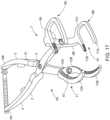
- FIGS 17 to 20 illustrate an embodiment of the invention of a bone reduction and plate fixation forceps is described, indicated generally by the reference numeral 60, in which parts described with reference to the previous embodiments are assigned the same reference numerals.
- the forceps comprises a first arm 2, second arm 3, and a pivot joint 4 providing pivoting scissors-like articulation of the arms.
- the pivot joint 4 is a conventional pivot joint used in orthopaedic forceps and will not be described in more detail.
- the first arm 2 has a proximal section 5 with a handle 6A and a bifurcated distal end 7 with diverging fork parts 8A, 8B each terminated in an n-shaped bone engaging jaw 9A, 9B.
- the fork parts 8A, 8B diverge at a right angle to an axis of the proximal section of the first arm.
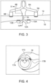
- the jaws 9A, 9B are used to grasp a first surface 14 of a fractured bone on each side of a fracture (as illustrated in Fig. 3 ).
- the jaws 9A, 9B are laterally spaced apart by about 6cm, although it will be appreciated that the spacing may be varied according to the bone being treated and the type of fracture.
- the second arm 3 has a proximal section 10 with a handle 6B and a bifurcated distal end 11 with diverging forks parts 12A, 12B each terminated in a bone engaging jaw 13A, 13B.
- the fork parts 12A, 12B diverge at a right angle to an axis of the proximal section of the second arm.
- the distal end 11 comprises a rotational joint 61 allowing the bifurcated distal end 11 a degree of rotation about an axis of the second arm 3.
- the jaws 13A, 13B are used to grasp a second surface 18 of a fractured bone on each side of a fracture 19 (as illustrated in Fig. 3 ).
- the jaws 13A, 13B are laterally spaced apart by about 3cm, although it will be appreciated that the spacing may be varied according to the bone being treated and the type of fracture.
- the bridge-shaped jaw is configured such that during use the distal and proximal jaw parts are circumferentially spaced around the top surface at an angle ⁇ of about 80° as shown in Fig. 4 .
- the recess has a height of about 4cm.
Landscapes
- Health & Medical Sciences (AREA)
- Orthopedic Medicine & Surgery (AREA)
- Life Sciences & Earth Sciences (AREA)
- Surgery (AREA)
- Medical Informatics (AREA)
- General Health & Medical Sciences (AREA)
- Biomedical Technology (AREA)
- Heart & Thoracic Surgery (AREA)
- Nuclear Medicine, Radiotherapy & Molecular Imaging (AREA)
- Molecular Biology (AREA)
- Animal Behavior & Ethology (AREA)
- Engineering & Computer Science (AREA)
- Public Health (AREA)
- Veterinary Medicine (AREA)
- Neurology (AREA)
- Ophthalmology & Optometry (AREA)
- Surgical Instruments (AREA)
- Food-Manufacturing Devices (AREA)
Claims (15)
- Knochenreduktions- und Plattenfixationszange (1), umfassend:einen ersten Arm (2) mit einem proximalen Teil (5), der einen Griff (6A) umfasst, und einem distalen Teil mit einem ersten knochenberührenden Kiefer (9A), der so konfiguriert ist, dass er eine erste Oberfläche (14) eines gebrochenen Knochens berührt; undeinen zweiten Arm (3) mit einem proximalen Teil (10), der einen Griff (6B) umfasst, und einem distalen Teil (11), der einen knochenberührenden Kiefer (13A) umfasst, der so konfiguriert ist, dass er eine zweite Oberfläche (18) des gebrochenen Knochens berührt, um den Knochen zwischen dem ersten und dem zweiten Arm zu klemmen;wobei der zweite Arm schwenkbar an dem ersten Arm durch ein erstes Gelenk (4) befestigt ist,das zwischen den jeweiligen Griffen und den jeweiligen knochenberührenden Kiefern des ersten und zweiten Arms angeordnet ist, dadurch gekennzeichnet, dass der erste Arm (2) einen bifurkierten distalen Teil mit einer ersten Gabel (8A) mit einem ersten knochenberührenden Kiefer (9A) und einer zweiten Gabel (8B) mit einem zweiten knochenberührenden Kiefer (9B) umfasst, wobei der erste knochenberührende Kiefer und der zweite knochenberührende Kiefer so konfiguriert sind, dass sie eine erste Oberfläche (14) eines gebrochenen Knochens auf jeder Seite des Bruchs (19) berühren, der zweite Arm umfasst (3) einen dritten knochenberührenden Kiefer (13A) und mindestens einer der ersten knochenberührenden Kiefer (9A) und der zweiten knochenberührenden Kiefer (9B) umfasst einen distalen knochenberührenden Kieferteil (17A), der durch einen erhöhten Brückenkieferteil (17C) mit einem proximalen knochenberührenden Kieferteil (17B) verbunden ist, der eine Plattenfixationsaufnahme (16) definiert, und wobei der erste knochenberührende Kiefer (9A) und der zweite knochenberührende Kiefer (9B) einen Abstand von 4 bis 8 cm haben.
- Knochenreduktions- und Plattenfixationszange gemäß Anspruch 1, wobei der distale Teil des ersten oder zweiten Arms ein Gelenk umfasst, das eine Drehbewegung eines distalen Endes des distalen Teils um eine Achse des distalen Teils des Arms ermöglicht.
- Knochenreduktions- und Plattenfixationszange (1) gemäß Anspruch 1 oder 2, wobei sowohl der erste knochenberührende Kiefer (9A) als auch der zweite knochenberührende Kiefer (9B) einen distalen knochenberührenden Kieferteil (17A) umfassen, der durch einen erhöhten Brückenkieferteil (17C) mit einem proximalen knochenberührenden Kieferteil (17B) verbunden ist, der eine Plattenfixationsaufnahme (16) definiert.
- Knochenreduktions- und Plattenfixationszange (1) gemäß einem der vorhergehenden Ansprüche, wobei der distale Teil (11) des zweiten Arms (3) bifurkiert ist und eine dritte Gabel (12A) umfasst, die den dritten knochenberührenden Kiefer (13A) umfasst, und eine vierte Gabel (12B), die den vierten knochenberührenden Kiefer (13B) umfasst, wobei der dritte knochenberührende Kiefer und der vierte knochenberührende Kiefer so konfiguriert sind, dass sie die zweite Oberfläche (18) des gebrochenen Knochens auf jeder Seite des Bruchs (19) berühren.
- Knochenreduktions- und Plattenfixationszange (1) gemäß Anspruch 4, wobei der erste knochenberührende Kiefer (9A) und der zweite knochenberührende Kiefer (9B) seitlich um eine erste Distanz D1 und der dritte knochenberührende Kiefer (13A) und der vierte knochenberührende Kiefer (14A) seitlich um eine zweite Distanz D2 beabstandet sind, wobei D1 mindestens 50 % größer ist als D2.
- Knochenreduktions- und Plattenfixationszange (1) gemäß einem der vorhergehenden Ansprüche, wobei der erste knochenberührende Kiefer (9A) und der zweite knochenberührende Kiefer (9B) seitlich um eine erste Distanz D1 beabstandet sind, wobei D1 von 5-7 cm beträgt.
- Knochenreduktions- und Plattenfixationszange (1) gemäß einem der vorhergehenden Ansprüche, wobei der dritte knochenberührende Kiefer (13A) und der vierte knochenberührende Kiefer (14A) seitlich um eine zweite Distanz D2 beabstandet sind, wobei D2 von 2-4 cm beträgt.
- Knochenreduktions- und Plattenfixationszange (1) gemäß einem der vorhergehenden Ansprüche, wobei die ersten und/oder zweiten knochenberührenden Kiefer ein bogenförmiges Profil haben.
- Knochenreduktions- und Plattenfixationszange gemäß Anspruch 8, wobei die distalen und proximalen knochenberührenden Kieferteile (17A, 17B) so konfiguriert sind, dass sie im Gebrauch um etwa 50-120° um die erste Oberfläche des Knochens herum beabstandet sind.
- Knochenreduktions- und Plattenfixationszange gemäß Anspruch 8 oder 9, wobei die Plattenfixationsaufnahme (16) eine Höhe von 2 bis 7 cm hat.
- Knochenreduktions- und Plattenfixationszange gemäß einem der vorhergehenden Ansprüche, wobei:die knochenberührenden Kiefer eine Vielzahl von Zähnen (22) umfassen; oderdie Knochenreduktions- und Plattenfixationszange einen Ratschmechanismus (15A, 15B) umfasst, der an einem der ersten und zweiten Arme befestigt ist.
- Knochenreduktions- und Plattenfixationszange gemäß Anspruch 2, wobei:das Drehgelenk am distalen Teil des Arms proximal von einem Bifurkationspunkt angeordnet ist;das Drehgelenk so konfiguriert ist, dass es die Drehung des distalen Endes des distalen Teils der ersten oder zweiten Arme um die Achse des distalen Teils des Arms auf 20°-100° begrenzt;das Drehgelenk so konfiguriert ist, dass es die Drehung des distalen Endes des distalen Teils der ersten oder zweiten Arme um die Achse des distalen Teils des Arms auf 50°-100° begrenzt; oderdas Drehgelenk so konfiguriert ist, dass es eine abnehmbare Verbindung des bifurkierten Teils des distalen Teils der Zange ermöglicht.
- Knochenreduktions- und Plattenfixationskit, umfassend:eine Knochenreduktions- und Plattenfixationszange (1) gemäß einem der vorhergehenden Ansprüche; undeine Plattenfixation (20).
- Knochenreduktions- und Plattenfixationskit gemäß Anspruch 13, wobei:die Plattenfixation eine dynamische Kompressionsplatte ist; oderdie Plattenfixation eine Querfraktur-Plattenfixation ist.
- Knochenreduktions- und Plattenfixationskit gemäß den Ansprüchen 13 oder 14, wobei:die Platte einen nach innen verjüngten Mittelteil zwischen ihren Enden in einer Längsansicht hat,wobei der distale knochenberührende Kieferteil (17A) und der proximale knochenberührende Kieferteil durch eine Distanz X beabstandet sind, wobei die Enden der Platte eine Breite haben, die gleich oder größer als X ist, und der nach innen verjüngte Mittelteil der Platte eine Breite hat, die kleiner als X ist, wodurch die Platte nach oben geneigt werden muss, um das Durchführen eines Endes der Platte unter dem Brückenkiefer zu ermöglichen, wodurch der nach innen verjüngte Mittelteil der Platte zwischen die Kieferteile passt, wenn sie flach gegen den Knochen liegt;
und/oderdie Plattenfixation hat mindestens ein Ende mit einer Breite von 14-16 mm undwobei der nach innen verjüngte Mittelteil eine Breite von 11-13 mm hat.
Applications Claiming Priority (3)
| Application Number | Priority Date | Filing Date | Title |
|---|---|---|---|
| GBGB2009483.5A GB202009483D0 (en) | 2020-06-22 | 2020-06-22 | A bone reduction and plate fixation forceps |
| GBGB2018936.1A GB202018936D0 (en) | 2020-12-01 | 2020-12-01 | A bone reduction and plate fixation forceps |
| PCT/EP2021/067046 WO2021259957A1 (en) | 2020-06-22 | 2021-06-22 | A bone reduction and plate fixation forceps |
Publications (3)
| Publication Number | Publication Date |
|---|---|
| EP4167880A1 EP4167880A1 (de) | 2023-04-26 |
| EP4167880B1 true EP4167880B1 (de) | 2025-02-26 |
| EP4167880C0 EP4167880C0 (de) | 2025-02-26 |
Family
ID=76730552
Family Applications (1)
| Application Number | Title | Priority Date | Filing Date |
|---|---|---|---|
| EP21736576.6A Active EP4167880B1 (de) | 2020-06-22 | 2021-06-22 | Knochenreduzierungs- und plattenfixierungszange |
Country Status (5)
| Country | Link |
|---|---|
| US (1) | US12453586B2 (de) |
| EP (1) | EP4167880B1 (de) |
| AU (1) | AU2021298117A1 (de) |
| CA (1) | CA3183511A1 (de) |
| WO (1) | WO2021259957A1 (de) |
Families Citing this family (2)
| Publication number | Priority date | Publication date | Assignee | Title |
|---|---|---|---|---|
| CN115300087A (zh) * | 2022-08-04 | 2022-11-08 | 中国人民解放军总医院第四医学中心 | 骨折复位板中置钳 |
| CN119279742A (zh) * | 2024-11-15 | 2025-01-10 | 南京市高淳中医院 | 一种骨科接骨钢板固定器 |
Citations (1)
| Publication number | Priority date | Publication date | Assignee | Title |
|---|---|---|---|---|
| US20180221068A1 (en) * | 2009-10-28 | 2018-08-09 | Orthopro Llc | Compression plate kit and methods for repairing bone discontinuities |
Family Cites Families (8)
| Publication number | Priority date | Publication date | Assignee | Title |
|---|---|---|---|---|
| US1985108A (en) * | 1933-12-18 | 1934-12-18 | Henry P Rush | Surgical instrument |
| US2460470A (en) * | 1946-11-27 | 1949-02-01 | Rogers Samuel Perry | Holding tool |
| ES2543012T3 (es) * | 2013-10-08 | 2017-08-10 | Karl Leibinger Medizintechnik Gmbh & Co. Kg | Pinzas de reposición con deformación doble de 90º para la distribución en dos planos |
| US10201891B2 (en) * | 2014-10-17 | 2019-02-12 | Matthew E. Williams | Alignment and adjustment clamp |
| CN106388925A (zh) * | 2016-11-23 | 2017-02-15 | 谢志进 | 一体化骨折复位固定钳 |
| GB2576187A (en) * | 2018-08-08 | 2020-02-12 | Brook Orthopaedics Ltd | A clamp and a cable |
| US11123125B2 (en) * | 2019-03-12 | 2021-09-21 | Jonathan L. Chang | Orthopedic clamps |
| CN217338801U (zh) * | 2022-04-29 | 2022-09-02 | 北京欧应科技有限公司 | 骨折复位钳 |
-
2021
- 2021-06-22 EP EP21736576.6A patent/EP4167880B1/de active Active
- 2021-06-22 AU AU2021298117A patent/AU2021298117A1/en not_active Abandoned
- 2021-06-22 WO PCT/EP2021/067046 patent/WO2021259957A1/en not_active Ceased
- 2021-06-22 CA CA3183511A patent/CA3183511A1/en active Pending
- 2021-06-22 US US18/002,147 patent/US12453586B2/en active Active
Patent Citations (1)
| Publication number | Priority date | Publication date | Assignee | Title |
|---|---|---|---|---|
| US20180221068A1 (en) * | 2009-10-28 | 2018-08-09 | Orthopro Llc | Compression plate kit and methods for repairing bone discontinuities |
Also Published As
| Publication number | Publication date |
|---|---|
| EP4167880A1 (de) | 2023-04-26 |
| CA3183511A1 (en) | 2021-12-30 |
| US12453586B2 (en) | 2025-10-28 |
| US20230218324A1 (en) | 2023-07-13 |
| EP4167880C0 (de) | 2025-02-26 |
| AU2021298117A1 (en) | 2023-02-02 |
| WO2021259957A1 (en) | 2021-12-30 |
Similar Documents
| Publication | Publication Date | Title |
|---|---|---|
| AU2003249649B2 (en) | Bone fixator with outrigger | |
| US8029507B2 (en) | Orthopedic method for correcting angular bone deformity | |
| RU2461365C2 (ru) | Инструменты для проведения хирургической операции на суставе | |
| AU2007250537A1 (en) | Ankle fusion plate | |
| US20030105526A1 (en) | High tibial osteotomy (HTO) wedge | |
| JP5449316B2 (ja) | ヒト患者の足首用の関節固定システム | |
| US20040172028A1 (en) | High tibial osteotomy device | |
| EP4412546B1 (de) | Fusionsplatte zur unterstützung der fusion eines ersten und zweiten knochens | |
| US12453586B2 (en) | Bone reduction and plate fixation forceps | |
| Richardson | Less invasive techniques for equine fracture repair and arthrodesis | |
| US20240016530A1 (en) | Bone reduction kit | |
| RU215005U1 (ru) | Репозиционный дистрактор для вправления застарелых задних вывихов плеча | |
| RU2195211C2 (ru) | Репозиционные щипцы | |
| CA1068573A (en) | Fluted hip nail implant system for orthopaedic surgery | |
| Smith | Fractures and luxations of the elbow | |
| GB2546089A (en) | A bone stabilisation device and uses thereof |
Legal Events
| Date | Code | Title | Description |
|---|---|---|---|
| STAA | Information on the status of an ep patent application or granted ep patent |
Free format text: STATUS: UNKNOWN |
|
| STAA | Information on the status of an ep patent application or granted ep patent |
Free format text: STATUS: THE INTERNATIONAL PUBLICATION HAS BEEN MADE |
|
| PUAI | Public reference made under article 153(3) epc to a published international application that has entered the european phase |
Free format text: ORIGINAL CODE: 0009012 |
|
| STAA | Information on the status of an ep patent application or granted ep patent |
Free format text: STATUS: REQUEST FOR EXAMINATION WAS MADE |
|
| 17P | Request for examination filed |
Effective date: 20221215 |
|
| AK | Designated contracting states |
Kind code of ref document: A1 Designated state(s): AL AT BE BG CH CY CZ DE DK EE ES FI FR GB GR HR HU IE IS IT LI LT LU LV MC MK MT NL NO PL PT RO RS SE SI SK SM TR |
|
| DAV | Request for validation of the european patent (deleted) | ||
| DAX | Request for extension of the european patent (deleted) | ||
| GRAP | Despatch of communication of intention to grant a patent |
Free format text: ORIGINAL CODE: EPIDOSNIGR1 |
|
| STAA | Information on the status of an ep patent application or granted ep patent |
Free format text: STATUS: GRANT OF PATENT IS INTENDED |
|
| RIC1 | Information provided on ipc code assigned before grant |
Ipc: A61B 17/88 20060101ALI20240531BHEP Ipc: A61B 17/80 20060101AFI20240531BHEP |
|
| INTG | Intention to grant announced |
Effective date: 20240624 |
|
| GRAS | Grant fee paid |
Free format text: ORIGINAL CODE: EPIDOSNIGR3 |
|
| GRAA | (expected) grant |
Free format text: ORIGINAL CODE: 0009210 |
|
| STAA | Information on the status of an ep patent application or granted ep patent |
Free format text: STATUS: THE PATENT HAS BEEN GRANTED |
|
| AK | Designated contracting states |
Kind code of ref document: B1 Designated state(s): AL AT BE BG CH CY CZ DE DK EE ES FI FR GB GR HR HU IE IS IT LI LT LU LV MC MK MT NL NO PL PT RO RS SE SI SK SM TR |
|
| REG | Reference to a national code |
Ref country code: GB Ref legal event code: FG4D |
|
| REG | Reference to a national code |
Ref country code: CH Ref legal event code: EP |
|
| REG | Reference to a national code |
Ref country code: DE Ref legal event code: R096 Ref document number: 602021026794 Country of ref document: DE |
|
| REG | Reference to a national code |
Ref country code: IE Ref legal event code: FG4D |
|
| U01 | Request for unitary effect filed |
Effective date: 20250319 |
|
| U07 | Unitary effect registered |
Designated state(s): AT BE BG DE DK EE FI FR IT LT LU LV MT NL PT RO SE SI Effective date: 20250324 |
|
| PG25 | Lapsed in a contracting state [announced via postgrant information from national office to epo] |
Ref country code: RS Free format text: LAPSE BECAUSE OF FAILURE TO SUBMIT A TRANSLATION OF THE DESCRIPTION OR TO PAY THE FEE WITHIN THE PRESCRIBED TIME-LIMIT Effective date: 20250526 |
|
| PG25 | Lapsed in a contracting state [announced via postgrant information from national office to epo] |
Ref country code: PL Free format text: LAPSE BECAUSE OF FAILURE TO SUBMIT A TRANSLATION OF THE DESCRIPTION OR TO PAY THE FEE WITHIN THE PRESCRIBED TIME-LIMIT Effective date: 20250226 |
|
| PG25 | Lapsed in a contracting state [announced via postgrant information from national office to epo] |
Ref country code: ES Free format text: LAPSE BECAUSE OF FAILURE TO SUBMIT A TRANSLATION OF THE DESCRIPTION OR TO PAY THE FEE WITHIN THE PRESCRIBED TIME-LIMIT Effective date: 20250226 |
|
| PG25 | Lapsed in a contracting state [announced via postgrant information from national office to epo] |
Ref country code: NO Free format text: LAPSE BECAUSE OF FAILURE TO SUBMIT A TRANSLATION OF THE DESCRIPTION OR TO PAY THE FEE WITHIN THE PRESCRIBED TIME-LIMIT Effective date: 20250526 Ref country code: IS Free format text: LAPSE BECAUSE OF FAILURE TO SUBMIT A TRANSLATION OF THE DESCRIPTION OR TO PAY THE FEE WITHIN THE PRESCRIBED TIME-LIMIT Effective date: 20250626 |
|
| PG25 | Lapsed in a contracting state [announced via postgrant information from national office to epo] |
Ref country code: HR Free format text: LAPSE BECAUSE OF FAILURE TO SUBMIT A TRANSLATION OF THE DESCRIPTION OR TO PAY THE FEE WITHIN THE PRESCRIBED TIME-LIMIT Effective date: 20250226 |
|
| PG25 | Lapsed in a contracting state [announced via postgrant information from national office to epo] |
Ref country code: GR Free format text: LAPSE BECAUSE OF FAILURE TO SUBMIT A TRANSLATION OF THE DESCRIPTION OR TO PAY THE FEE WITHIN THE PRESCRIBED TIME-LIMIT Effective date: 20250527 |
|
| U21 | Renewal fee for the european patent with unitary effect paid with additional fee |
Year of fee payment: 5 Effective date: 20250701 |
|
| PG25 | Lapsed in a contracting state [announced via postgrant information from national office to epo] |
Ref country code: SM Free format text: LAPSE BECAUSE OF FAILURE TO SUBMIT A TRANSLATION OF THE DESCRIPTION OR TO PAY THE FEE WITHIN THE PRESCRIBED TIME-LIMIT Effective date: 20250226 |
|
| PG25 | Lapsed in a contracting state [announced via postgrant information from national office to epo] |
Ref country code: CZ Free format text: LAPSE BECAUSE OF FAILURE TO SUBMIT A TRANSLATION OF THE DESCRIPTION OR TO PAY THE FEE WITHIN THE PRESCRIBED TIME-LIMIT Effective date: 20250226 |
|
| PG25 | Lapsed in a contracting state [announced via postgrant information from national office to epo] |
Ref country code: SK Free format text: LAPSE BECAUSE OF FAILURE TO SUBMIT A TRANSLATION OF THE DESCRIPTION OR TO PAY THE FEE WITHIN THE PRESCRIBED TIME-LIMIT Effective date: 20250226 |
|
| PLBE | No opposition filed within time limit |
Free format text: ORIGINAL CODE: 0009261 |
|
| STAA | Information on the status of an ep patent application or granted ep patent |
Free format text: STATUS: NO OPPOSITION FILED WITHIN TIME LIMIT |
|
| REG | Reference to a national code |
Ref country code: CH Ref legal event code: L10 Free format text: ST27 STATUS EVENT CODE: U-0-0-L10-L00 (AS PROVIDED BY THE NATIONAL OFFICE) Effective date: 20260107 |
|
| REG | Reference to a national code |
Ref country code: CH Ref legal event code: H13 Free format text: ST27 STATUS EVENT CODE: U-0-0-H10-H13 (AS PROVIDED BY THE NATIONAL OFFICE) Effective date: 20260127 |
|
| PG25 | Lapsed in a contracting state [announced via postgrant information from national office to epo] |
Ref country code: MC Free format text: LAPSE BECAUSE OF FAILURE TO SUBMIT A TRANSLATION OF THE DESCRIPTION OR TO PAY THE FEE WITHIN THE PRESCRIBED TIME-LIMIT Effective date: 20250226 |
|
| 26N | No opposition filed |
Effective date: 20251127 |
|
| GBPC | Gb: european patent ceased through non-payment of renewal fee |
Effective date: 20250622 |
|
| PG25 | Lapsed in a contracting state [announced via postgrant information from national office to epo] |
Ref country code: GB Free format text: LAPSE BECAUSE OF NON-PAYMENT OF DUE FEES Effective date: 20250622 |
|
| PG25 | Lapsed in a contracting state [announced via postgrant information from national office to epo] |
Ref country code: IE Free format text: LAPSE BECAUSE OF NON-PAYMENT OF DUE FEES Effective date: 20250622 |
|
| PG25 | Lapsed in a contracting state [announced via postgrant information from national office to epo] |
Ref country code: CH Free format text: LAPSE BECAUSE OF NON-PAYMENT OF DUE FEES Effective date: 20250630 |