EP4168926B1 - Verfahren und system zur abbildung von sich bewegenden druckmaterialien - Google Patents
Verfahren und system zur abbildung von sich bewegenden druckmaterialien Download PDFInfo
- Publication number
- EP4168926B1 EP4168926B1 EP21826818.3A EP21826818A EP4168926B1 EP 4168926 B1 EP4168926 B1 EP 4168926B1 EP 21826818 A EP21826818 A EP 21826818A EP 4168926 B1 EP4168926 B1 EP 4168926B1
- Authority
- EP
- European Patent Office
- Prior art keywords
- printed material
- cameras
- images
- controller device
- imaging controller
- Prior art date
- Legal status (The legal status is an assumption and is not a legal conclusion. Google has not performed a legal analysis and makes no representation as to the accuracy of the status listed.)
- Active
Links
Images




Classifications
-
- H—ELECTRICITY
- H04—ELECTRIC COMMUNICATION TECHNIQUE
- H04N—PICTORIAL COMMUNICATION, e.g. TELEVISION
- H04N1/00—Scanning, transmission or reproduction of documents or the like, e.g. facsimile transmission; Details thereof
- H04N1/00127—Connection or combination of a still picture apparatus with another apparatus, e.g. for storage, processing or transmission of still picture signals or of information associated with a still picture
- H04N1/00249—Connection or combination of a still picture apparatus with another apparatus, e.g. for storage, processing or transmission of still picture signals or of information associated with a still picture with a photographic apparatus, e.g. a photographic printer or a projector
- H04N1/00251—Connection or combination of a still picture apparatus with another apparatus, e.g. for storage, processing or transmission of still picture signals or of information associated with a still picture with a photographic apparatus, e.g. a photographic printer or a projector with an apparatus for taking photographic images, e.g. a camera
-
- H—ELECTRICITY
- H04—ELECTRIC COMMUNICATION TECHNIQUE
- H04N—PICTORIAL COMMUNICATION, e.g. TELEVISION
- H04N1/00—Scanning, transmission or reproduction of documents or the like, e.g. facsimile transmission; Details thereof
- H04N1/00127—Connection or combination of a still picture apparatus with another apparatus, e.g. for storage, processing or transmission of still picture signals or of information associated with a still picture
- H04N1/00204—Connection or combination of a still picture apparatus with another apparatus, e.g. for storage, processing or transmission of still picture signals or of information associated with a still picture with a digital computer or a digital computer system, e.g. an internet server
- H04N1/00209—Transmitting or receiving image data, e.g. facsimile data, via a computer, e.g. using e-mail, a computer network, the internet, I-fax
-
- H—ELECTRICITY
- H04—ELECTRIC COMMUNICATION TECHNIQUE
- H04N—PICTORIAL COMMUNICATION, e.g. TELEVISION
- H04N1/00—Scanning, transmission or reproduction of documents or the like, e.g. facsimile transmission; Details thereof
- H04N1/00127—Connection or combination of a still picture apparatus with another apparatus, e.g. for storage, processing or transmission of still picture signals or of information associated with a still picture
- H04N1/00326—Connection or combination of a still picture apparatus with another apparatus, e.g. for storage, processing or transmission of still picture signals or of information associated with a still picture with a data reading, recognizing or recording apparatus, e.g. with a bar-code apparatus
- H04N1/00328—Connection or combination of a still picture apparatus with another apparatus, e.g. for storage, processing or transmission of still picture signals or of information associated with a still picture with a data reading, recognizing or recording apparatus, e.g. with a bar-code apparatus with an apparatus processing optically-read information
-
- H—ELECTRICITY
- H04—ELECTRIC COMMUNICATION TECHNIQUE
- H04N—PICTORIAL COMMUNICATION, e.g. TELEVISION
- H04N1/00—Scanning, transmission or reproduction of documents or the like, e.g. facsimile transmission; Details thereof
- H04N1/0035—User-machine interface; Control console
- H04N1/00352—Input means
- H04N1/00355—Mark-sheet input
- H04N1/00358—Type of the scanned marks
-
- H—ELECTRICITY
- H04—ELECTRIC COMMUNICATION TECHNIQUE
- H04N—PICTORIAL COMMUNICATION, e.g. TELEVISION
- H04N1/00—Scanning, transmission or reproduction of documents or the like, e.g. facsimile transmission; Details thereof
- H04N1/0035—User-machine interface; Control console
- H04N1/00501—Tailoring a user interface [UI] to specific requirements
-
- H—ELECTRICITY
- H04—ELECTRIC COMMUNICATION TECHNIQUE
- H04N—PICTORIAL COMMUNICATION, e.g. TELEVISION
- H04N1/00—Scanning, transmission or reproduction of documents or the like, e.g. facsimile transmission; Details thereof
- H04N1/00681—Detecting the presence, position or size of a sheet or correcting its position before scanning
- H04N1/00729—Detection means
- H04N1/00734—Optical detectors
-
- H—ELECTRICITY
- H04—ELECTRIC COMMUNICATION TECHNIQUE
- H04N—PICTORIAL COMMUNICATION, e.g. TELEVISION
- H04N1/00—Scanning, transmission or reproduction of documents or the like, e.g. facsimile transmission; Details thereof
- H04N1/00681—Detecting the presence, position or size of a sheet or correcting its position before scanning
- H04N1/00763—Action taken as a result of detection
- H04N1/00774—Adjusting or controlling
- H04N1/00779—Adjusting settings, e.g. mode, feeding rate or type of paper
-
- H—ELECTRICITY
- H04—ELECTRIC COMMUNICATION TECHNIQUE
- H04N—PICTORIAL COMMUNICATION, e.g. TELEVISION
- H04N1/00—Scanning, transmission or reproduction of documents or the like, e.g. facsimile transmission; Details thereof
- H04N1/024—Details of scanning heads ; Means for illuminating the original
- H04N1/028—Details of scanning heads ; Means for illuminating the original for picture information pick-up
- H04N1/02815—Means for illuminating the original, not specific to a particular type of pick-up head
-
- G—PHYSICS
- G06—COMPUTING OR CALCULATING; COUNTING
- G06F—ELECTRIC DIGITAL DATA PROCESSING
- G06F3/00—Input arrangements for transferring data to be processed into a form capable of being handled by the computer; Output arrangements for transferring data from processing unit to output unit, e.g. interface arrangements
- G06F3/12—Digital output to print unit, e.g. line printer, chain printer
- G06F3/1201—Dedicated interfaces to print systems
- G06F3/1223—Dedicated interfaces to print systems specifically adapted to use a particular technique
- G06F3/1237—Print job management
- G06F3/1242—Image or content composition onto a page
- G06F3/1243—Variable data printing, e.g. document forms, templates, labels, coupons, advertisements, logos, watermarks, transactional printing, fixed content versioning
-
- G—PHYSICS
- G06—COMPUTING OR CALCULATING; COUNTING
- G06K—GRAPHICAL DATA READING; PRESENTATION OF DATA; RECORD CARRIERS; HANDLING RECORD CARRIERS
- G06K15/00—Arrangements for producing a permanent visual presentation of the output data, e.g. computer output printers
- G06K15/02—Arrangements for producing a permanent visual presentation of the output data, e.g. computer output printers using printers
- G06K15/18—Conditioning data for presenting it to the physical printing elements
- G06K15/1867—Post-processing of the composed and rasterized print image
- G06K15/1882—Post-processing of the composed and rasterized print image involving operator action
- G06K15/1885—Post-processing of the composed and rasterized print image involving operator action for modifying the layout of a document
-
- G—PHYSICS
- G06—COMPUTING OR CALCULATING; COUNTING
- G06V—IMAGE OR VIDEO RECOGNITION OR UNDERSTANDING
- G06V30/00—Character recognition; Recognising digital ink; Document-oriented image-based pattern recognition
- G06V30/10—Character recognition
- G06V30/14—Image acquisition
- G06V30/146—Aligning or centring of the image pick-up or image-field
- G06V30/147—Determination of region of interest
-
- H—ELECTRICITY
- H04—ELECTRIC COMMUNICATION TECHNIQUE
- H04N—PICTORIAL COMMUNICATION, e.g. TELEVISION
- H04N1/00—Scanning, transmission or reproduction of documents or the like, e.g. facsimile transmission; Details thereof
- H04N1/00127—Connection or combination of a still picture apparatus with another apparatus, e.g. for storage, processing or transmission of still picture signals or of information associated with a still picture
- H04N1/00132—Connection or combination of a still picture apparatus with another apparatus, e.g. for storage, processing or transmission of still picture signals or of information associated with a still picture in a digital photofinishing system, i.e. a system where digital photographic images undergo typical photofinishing processing, e.g. printing ordering
- H04N1/00135—Scanning of a photographic original
Definitions
- the present disclosure is related generally to imaging technology and, more particularly, to printed material imaging applications.
- some systems may extract information from labels or barcodes that are known to be genuine, for example by processing images of labels or barcodes that are known to be genuine, and may subsequently use this information to authenticate products bearing presumably the same labels or barcodes.
- Optical systems sometimes are utilized to obtain images of moving material, for example for quality inspection and defect detection during production of the material and/or to extract useful information from images of the printed materials.
- Such systems often use line scan technology to obtain images of the moving material.
- Line scan technology requires accurate tracking of motion of the printed material to obtain images with sufficiently high resolutions, which may not be feasible in high speed image acquisition applications.
- Line scan systems may also be physically too large to fit in tight areas that may be available for optical systems at sites manufacturing the materials.
- Patent document EP3599094 refers to a system for capturing images of printed material. This document discloses determining a trigger interval to capture a particular region of interest in the context of a system for capturing images during production of printed material.
- a system for capturing images during production of printed material comprises an optical device comprising a plurality of cameras arranged in an array, wherein adjacent pairs of cameras in the array have overlapping fields of view.
- the system also comprises an imaging controller device configured to determine a layout of content on printed material, and determine, based on the layout of content on the printed material, an optical system configuration profile.
- Determining the optical system configuration profile includes i) selecting one or more cameras, among the plurality of cameras, for capturing images of one or more regions of interest on the printed material, the one or more cameras being selected such that each region of interest among the one or more regions of interest fits, in its entirety, in a field of view of a particular camera among the one or more cameras, and ii) determining a trigger interval for triggering the selected one or more cameras.
- the imaging controller device is further configured to trigger the selected one or more cameras at times determined based on the trigger interval to capture images of the one or more regions of interest on the printed material as the printed material moves in fields of view of the one or more cameras during production of the printed material.
- a method for capturing images of printed material by an optical device equipped with a plurality of cameras arranged in an array, wherein adjacent pairs of cameras in the array have overlapping fields of view includes determining, with a processor of an imaging controller device, a layout of content on printed material.
- the method also includes determining, with the processor of the imaging controller device based on the layout of content on the printed material, an optical system configuration profile, including i) selecting one or more cameras, among the plurality of cameras, for capturing images of one or more regions of interest on the printed material, the one or more cameras being selected such that each region of interest among the one or more regions of interest fits, in its entirety, in a field of view of a particular camera among the one or more cameras, and ii) determining a trigger interval for triggering the selected one or more cameras.
- the method additionally includes triggering, with the imaging controller device, the selected one or more cameras at times determined based on the trigger interval to capture images of the one or more regions of interest on the printed material as the printed material moves in fields of view of the one or more cameras during production of the printed material.
- an imaging system is utilized to acquire and process images of regions of interest on printed materials during production runs performed in producing the printed materials.
- the imaging system may acquire images of marks on labels during production of the labels, and may process the images of the marks to generate identifiable electronic signatures ("signatures") that may subsequently be utilized for authentication of products presumably bearing the genuine marks.
- the imaging system is generally described herein in the context of printed labels, and generation of signatures for marks on the printed labels, merely for exemplary purposes.
- the imaging system may be utilized in other manufacturing application.
- the imaging system may be utilized for detection of defects in printed materials, or for acquiring and processing images of materials other than printed materials.
- the imaging system may include an optical device comprising an imaging array having a plurality of area scan cameras.
- the imaging array me be arranged such that respective cameras in the array have overlapping fields of view.
- the optical device may be installed at a manufacturing site that may utilize a production apparatus to produce printed material, such as a label manufacturer that may utilize label printers, label converters, slitters, rewinders, and the like, to produce reels of printed labels, for example.
- the imaging system may also include a controller device configured to control operation of the optical device during a production run that may be performed by the production apparatus.
- the controller device may determine a layout of content on the printed material, such as a layout of a web of labels that may be printed on the printed material.
- the controller device may generate an optical system configuration profile to be used to control the optical device during the production run performed by the production apparatus in manufacturing of the printed material. For example, the controller device may determine locations of regions of interest on the printed materials, and may select one or more cameras in the imaging array to be used for capturing images of the regions of interest on the printed material.
- the one or more regions of interest on the printed material may include marks, such as barcodes, 2-D codes (e.g., QR codes), logos, etc., that may be printed on labels, for example.
- the controller device may also determine a trigger interval for triggering the selected one or more cameras such that the selected cameras are triggered at appropriate times as the printed material moves through cameras' fields of view during production of the printed material to accurately capture images of regions of interest on the printed material.
- the controller device may trigger the selected one or more cameras at times at which the one or more regions of interest on the printed material are aligned with the fields of view of the selected cameras.
- the controller device may be guided by sensor and encoder signals that the controller device may receive from the production apparatus to detect reference points on the printed material and a distance of travel of the printed material to ensure that the images are captured at precise times when the regions of interest are aligned with the fields of view of the cameras, in some embodiments.
- the imaging system may process the acquired images, for example to extract signature information from marks that may be depicted in the images.
- the imaging system may be equipped with a multi-core processor and/or may utilize multi-threading techniques to process the images.
- the imaging system may include an interface communicatively coupled to a network, and may be configured to communicate with other devices via the network.
- the imaging system may transmit the acquired images and/or information extracted from the acquired images, via the network, to a database and/or to a server device, where the acquired images and/or information extracted from the acquired images may be stored and subsequently utilized for authentication of products presumably bearing the marks that are depicted in the images.
- the imaging system may acquire images of the regions of interest with a suitably short camera exposures that may be needed to prevent or minimize motion blur from images, particularly in applications with high speed moving printed materials, and to acquire sufficiently clear images that allow extraction of signatures from the images of the regions of interest and/or accurate inspection of the printed materials in the regions of interest. Further, providing cameras with overlapping fields of view, and selecting appropriate cameras for capturing of the images such that each region of interest is captured by a single camera in a single image, allows for fast and efficient processing of the images which, in tum, allows the imaging system to quickly and efficiently process a large volume of images that may be acquired during the production run, in at least some embodiments.
- Fig. 1 is a block diagram of an example system 100 in which an imaging system 102 may operate to acquire and process images of regions of interest in printed material 104 produced by a production apparatus 106, according to an embodiment.
- the production apparatus 106 may be a printer, a label converter, a slitter, a rewinder, or any other equipment that may be used in producing the printed material 104.
- the printed material 104 may be a label web, for example, or may be any other suitable type of printed material. Regions of interest on the printed material 104 may include marks that may be printed on labels, for example.
- a mark may be something that identifies a brand (e.g., a logo), something that bears information, such as a barcode (e.g., a one-dimensional ("1D") barcode, such as such as European Article Number (EAN), Universal Product Code (UPC), Interleaved Two of Five (ITF) code, etc., a two-dimensional ("2D") data matrix barcode as specified in the International Organization for Standardization (“ISO”) and the International Electrotechnical Commission (“IEC”) standard ISO/IEC 16022, a Quick Response (QR) code, etc.), an expiration date, or tracking information such as a serial number), or a decoration.
- the printed material 104 may include other suitable regions of interest.
- the imaging system 102 may include an optical device 108 and an imaging controller device 110.
- the imaging controller device 110 is illustrated in Fig. 1 as being separate from, and external to, the optical device 108, the imaging controller device 110 may be integrated with the optical device 108 in other embodiments.
- the optical device 108 may be equipped with an imaging array 112 having a plurality of imaging sensors (e.g., cameras) 114.
- the optical device 108 may be positioned in the vicinity of (e.g., above) the production apparatus 106 such that the printed material 104 moves through fields of view of the cameras 114 during a production run that may be performed by the production apparatus 106 in producing the printed material 104.
- the imaging array 112 may include a linear arrangement of eight cameras 114. In other embodiments, the imaging array 112 may include other suitable numbers of cameras 114 and/or the cameras 114 may be arranged in suitable non-linear arrangements.
- the cameras 114 may be area scan cameras configured to capture an image containing a two dimensional (2D) pixel matrix in a single exposure cycle. Multiple ones of the cameras 114 may operate in parallel to capture images of wider printed materials as compared to systems where only a single area scan camera is utilized, in at least some embodiments.
- the cameras 114 may comprise imaging sensors of relatively high resolution, such as 20 ⁇ m/pixel or higher resolution, in an embodiment. As an example, VCXU-123M model cameras manufactured by Baumer may be utilized as the cameras 114.
- the cameras 114 may be arranged such that respective cameras 114 have overlapping fields of view.
- a field of view of the camera 114-2 may overlap with respective fields of view of the camera 114-1 and 114-3
- the field of view of the camera 114-3 may overlap with respective fields of view of cameras 114-2 and 114-4, and so on, in an embodiment.
- Degrees of overlap between the respective fields of view of the cameras 114 may vary in various embodiments. For example a 50% overlap may be utilized, in an embodiments. In other embodiments, other suitable degrees of overlap (e.g., 25%, 75%, 100%, 125%, 150%, etc.) may be utilized.
- the imaging controller device 110 may include an image acquisition controller 116, a processor 118 and a computer readable memory 120 that stores computer readable instructions executable by processor 118.
- the computer readable memory 120 may include volatile memory to store computer instructions, such as Random Access Memory (RAM), and may also include persistent memory such as, for example, a hard disk, hard-drive or any other stable storage space, e.g. a secure digital ("SD") card, a flash drive, etc., in various embodiments.
- the computer readable memory 120 may store a configuration application 122 and an image processing application 124.
- the imaging controller device 110 is illustrated in Fig. 1 as including a single processor 118, the imaging controller device 110 may include multiple processors 118 in some embodiments.
- the one or multiple processors 118 may be multi-core processors and/or may utilize multi-threading to perform processing operations.
- the processor 118 may comprise 12 cores, 16 cores, 64 cores, or any other suitable number of cores.
- the configuration application 122 and/or the image processing application 124 may be implemented using hardware components, firmware components, software components, or any combination thereof.
- the configuration application 122 may obtain information descriptive of specific layout of content on the printed material 104, and may determine an optical system configuration profile based on the specific layout of content on the printed material 104.
- the configuration application 122 may obtain information that indicates a width of the label web sheet, a number of lanes of labels that may run across the width of the label web sheet, a height and width of each label on the label web sheet, a distance between adjacent labels on the web sheet, and a location and size of a region of interest, such as a barcode, in each label on the label web sheet, and the like.
- the configuration application 122 may determine the specific layout of the content on the printed material 104 based on user input.
- the configuration application 122 may provide a user interface that may request information descriptive of the specific layout of the content on the printed material 104.
- the imaging controller device 110 may determine the specific layout of content on the printed material 104 by applying suitable image processing techniques to one or more sample images that may depict the content of the printed material 104.
- the one or more sample images may be obtained by the imaging controller device 110 by suitably controlling operation of the optical device 108 during a production run (e.g., during a sample production run or during an initial stage of a real production run) that may be performed by the production apparatus 106 in producing the printed material 104.
- the imaging controller device 110 may trigger particular cameras 114 (e.g., all cameras 114 or particular subset or subsets of cameras 114) at one or more sample trigger intervals as the printed material 104 moves in the fields of view of the cameras 114 during the production run.
- the imaging controller device 110 may process images captured by the particular cameras 114 triggered during the production run to determine the layout of content on the printed material 104, in an embodiment.
- the imaging controller device 110 may obtain the one or more sample images of the content on the printed material 104 in other suitable manners and/or may determine the specific layout of content on the printed material 104 using suitable techniques other than processing sample images of the content on the printed material 104 obtained during a production run performed by the production apparatus 106.
- the configuration application 122 may determine an optical system configuration profile to be used for controlling the optical device 108 during production of the printed material 104 by the production apparatus 106. Determining the optical system configuration may include selecting, based on the layout of the content on the printed material 104, one or more cameras 114 to be triggered to obtain images of the regions of interest during movement of the printed material 104 as the printed material 104 is produced or processed by the production apparatus 106.
- the configuration application 122 selects a particular camera 114 that will have the region of interest, in its entirety, in its field of view during movement of the printed material 104 through its field of view.
- Such camera selection ensures that appropriate cameras 114 are triggered during production of the printed material 104 so that one or more particular regions of interest (e.g., one or more barcodes) are captured, in their entireties, in a single image by a single camera 114, in an embodiment.
- Ensuring that each region of interest on the printed material 104 is captured, in its entirety, in a single image facilitates processing of the images because the images can be processed independently of each other to extract useful information from the region of interest captured in each image, in at least some embodiments.
- Arranging cameras 114 in an array with adjacent cameras 114 having overlapping fields of view ensures that for various layout of content of printed material 104, such as various layouts of labels and various locations and sizes of regions of interest within the labels on the printed material 104, a single camera 114 can be selected to capture each region of interest in its entirety, ensuring that a single image will entirely contain the region of interest, in at least some embodiments. In some situations, for certain layouts of content on the printed material 104, multiple cameras 114 among the plurality of cameras 114 may be available to capture a region of interest in its entirety as the printed material 104 moves through the fields of view of the camera 114.
- each of the multiple cameras 114 may have a region of interest, in its entirety, in its field of view as the printed material 104 moves through the fields of view of the multiple cameras 114.
- the configuration application 122 may select one of the multiple available cameras 114 to be used for capturing the region of interest during the production process as the printed material 104 moves through the field of view of the selected camera 114.
- the configuration application 120 may select a particular camera 114 among the multiple available cameras 114 based on respective locations of the region of interest within the fields of view of the multiple available cameras 114.
- the configuration application 120 may select a particular camera 114 for which the region of interest is closest to the center of its field of view.
- the configuration application 120 may utilize different selection criteria to select a particular camera 114 among the multiple available cameras 114.
- a user may use a user interface to specify cameras 114 to be selected, in an embodiment.
- Determining the optical system configuration profile may additionally include determining a trigger interval to be used for triggering the selected cameras 114 during the production run on the production apparatus 106.
- the configuration application 122 may determine, for example, a timing or a distance interval with respect to specific reference lines that may run across the width of the printed material 104. As an example, if the regions of interest correspond to barcodes on labels, the configuration application 122 may determine a distance interval from a beginning of a row of labels, along a perpendicular line, to a center of the barcode. As another example, the configuration application 122 may determine, based on expected speed of movement of the printed material, a time interval for the printed material to travel from a beginning of a row of labels, along a perpendicular line, to a center of the barcode.
- the image acquisition controller 116 may utilize the optical system configuration profile determined by the configuration application 122 to control operation of the optical device 108 during a production run performed by the production apparatus 106.
- the configuration application 122 may store the determined optical system configuration profile in an optical system configuration profile memory (not shown in Fig. 1 ) that may store respective optical system configuration profiles determined for different layouts of the printed material 104 that the production apparatus 106 may be configured to produce in different production runs, or as parts of a same production run.
- the imaging controller device 110 may be configured to retrieve, from the optical system configuration profile memory, appropriate optical system configuration profiles to be used to control operation of the optical device 108 during particular production runs performed by the production apparatus 106.
- a user may specify, via a user interface, which particular optical system configuration profile is to be retrieved from the memory for particular production run.
- the user may utilize the user interface to select, or otherwise specify, a particular job (e.g., a particular print job) to be performed by the production apparatus 106 during the production run, where the particular job is associated with a particular layout of content on the printed material 104.
- the imaging controller device 110 e.g., the image acquisition controller 116 or another component of the imaging controller device 110
- the image acquisition controller 116 may detect the particular layout of content on the printed material 104 based on receiving, from the production apparatus 106, a signal (e.g., an Ethernet internet protocol (IP) command or another suitable signal) indicating that a particular production run associated with a particular layout of content on the printed material 104 that is to be produced by the production apparatus 106.
- a signal e.g., an Ethernet internet protocol (IP) command or another suitable signal
- IP internet protocol
- the imaging controller device 110 may detect the particular layout of content on the printed material 104 by processing a code, such as a QR code or another suitable code, that may be printed on an area in the printed material 104 (e.g., on a side of a label web printed on the printed material 104).
- the code that may be printed on an area in the printed material 104 may indicate a particular production run (e.g., a particular print job) that may be associated with a particular layout of content on the printed material 104 that is to be produced by the production apparatus 106.
- a camera 114 of the imaging array 112 may be used to capture images of the area on the printed material 104 during an initial stage of a production run to be performed by the production apparatus 106.
- a camera (not shown in Fig. 1 ) separate from the imaging array 112 may be provided to capture images of the area on the printed material 104 during an initial stage of a production run to be performed by the production apparatus 106.
- One or more images captured by the camera 114 of the imaging array 112 or by the camera separate from the imaging array 112 may be processed by the imaging controller device 110 to detect and decode the code that may be printed on the area of the printed material 104.
- the imaging controller device 110 may then retrieve, from the optical system configuration profile memory based on the information indicated by the code, an appropriate optical system configuration profile to be used to control operation of the optical device 108 during the production run.
- the imaging controller device 110 may retrieve appropriate optical system configuration profiles from the optical system configuration profile memory dynamically during operation of the production apparatus 106, for example in scenarios in which a layout of the content on the printed material 104 may dynamically change during the production run performed by the production apparatus 106.
- the imaging controller device 110 e.g., the image acquisition controller 116 or another component of the imaging controller device 110
- signals e.g., an Ethernet internet protocol (IP) command or another suitable signals
- the printed material 104 may include a code, such as a QR code or another suitable code, that may be printed on an area of the printed material 104 (e.g., on a side of a label web printed on the printed material 104) as described above, immediately preceding or concurrently with a change to a new layout of content on the printed material 104.
- the imaging controller device 110 may process one or more images of the area on the printed material 104 that may be captured by a camera 114 of the imaging array 112 or by a camera mandate from the imaging array 112 as described above to detect the switch to the new layout on the printed material 104.
- the imaging controller device 110 may determine which particular optical system configuration profiles are to be retrieved from the optical system configuration profile memory "on the fly" during a production run, and may retrieve the system configuration profiles to be used to control operation of the optical device 108 at the appropriate times during the production run that produces printed material 104.
- the image acquisition controller 116 may trigger the one or more cameras 114 selected by the configuration application 122 at times that may be determined by the trigger interval determined by the configuration application 122 so that the selected cameras 114 are triggered at appropriate times to capture images of the regions of interest on the printed material 104 during movement of the printed material 104 through the fields of view of the selected one or more cameras 114.
- the optical device 108 may also include one or more light sources (not shown in Fig. 1 ), which may be high intensity light emitting devices, such as light emitting diodes (LEDs), for example.
- the image acquisition controller 116 may trigger the light sources of the optical device 108 at least substantially simultaneously with triggering the cameras 114 of the optical device 108 to provide short, high intensity, flashes of light during capture of images by the cameras 114 in order to obtain sufficiently clear images of the regions of interest on the printed material 104, for example.
- the production apparatus 106 may be equipped with a sensor 128 and an encoder 130.
- the sensor 128 may be configured to detect certain points of reference on the printed material 104 as the printed material 104 moves during operation of the production apparatus 106, and to generate sensor signals indicating the points of reference on the printed material 104.
- the encoder 130 may track motion of the printed material 104, and to generate encoder signals that indicate the movement of the printed material 104.
- the image acquisition controller 116 may receive sensor signals generated by the sensor 128 and encoder signals generated by the encoder 130 during operation of the production apparatus 106, and may be guided by the signals to implement precise triggering of the selected cameras 114 based on the triggering interval determined by the configuration application 122.
- the sensor 128 may detect a label edge in a row of labels, and the sensor signal provided to the image acquisition controller 116 may indicate that a label edge of a row of labels has passed a reference point.
- the encoder signal provided to the image acquisition controller 116 by the encoder 130 may, in turn, indicate a distance that the printed material 104 has traveled from the reference point.
- the image acquisition controller 116 may trigger the cameras 114 at a point when the printed material 104 has progressed from the reference point by a distance (or time) that corresponds to the trigger interval determined by the configuration application 122.
- the selected cameras 114 may, in parallel, capture images of the regions of interest on each label in the row of labels. This process may be repeated as each row of labels on the printed material 104 passes the reference point by a distance (or time) that corresponds to the trigger interval determined by the configuration application 122.
- the image acquisition controller 116 may acquire images of the regions of interest on the printed material 104 with suitably short camera exposures (e.g., 5 ⁇ s exposure times or other suitable short exposure times) that may be needed to prevent or minimize motion blur from the images, for example in application with high speed moving printed materials (e.g., moving at 2 m/sec or moving at other relatively high speeds), and to acquire sufficiently clear images that allow extraction of signatures from the images of the regions of interest on the printed material 104.
- suitably short camera exposures e.g., 5 ⁇ s exposure times or other suitable short exposure times
- the image acquisition controller 116 may provide the images acquired from the optical device 108 to the processor 118 for processing of the images by the processor 118.
- the images may be processed by the processor 118 as the images are acquired during the production run performed by the production apparatus 106, and processed images may be discarded so that new images can be acquired and processed by the processor 118, in an embodiment.
- the processor 118 may implement the image processing application 124 to process the images. Processing the images may include using unintentionally-produced artifacts within a mark depicted in the image to define an identifiable electronic signature ("signature") that may subsequently be used to authenticate a candidate mark that presumably corresponds to the mark depicted in the image.
- signature identifiable electronic signature
- artifact is a feature of a mark that was produced by the machine or process that created the mark, but not by design or intention (i.e., an irregularity).
- examples of artifacts include: (a) deviation in average color of a subarea (e.g., a cell of a 2D barcode) from an average derived from within the mark (which may be an average for neighboring cells of the same nominal color), (b) bias in the position of a subarea relative to a best-fit grid of neighboring subareas, (c) areas of a different one of at least two colors from a nominal color of the cells, (d) deviation from a nominal shape of a continuous edge within the mark, and (e) imperfections or other variations resulting from the mark being printed.
- the processor 118 utilizes multiple cores and/or implements multi-threading techniques to more quickly process the images acquired during production of the printed material 104.
- multiple cores of the processor 118 and/or multiple threads implemented by the processor 118 may operate in parallel to perform processing of respective regions of interest on the printed material 104 captured in respective images by respective cameras 104.
- multiple cores of the processor 118 and/or multiple threads implemented by processor 118 may operate in parallel to process respective barcodes that may be captured, in their entireties, by respective cameras 114.
- multiple cores of the processor 118 and/or multiple threads implemented by processor 118 may operate in parallel to process portions of a single barcode that may be split into respective portions (e.g., respective halves of an EAN code that may be separated by a central guard on the EAN code) to enable parallel processing of the respective portions of the barcode.
- the respective portions of the barcode may be captured in different images by different cameras 114 during production of the printed material 104.
- an entire barcode captured in a single image by a single camera 114 during production of the printed material 104 may be pre-processed by the processor 118 to parse out portions of the barcode for parallel processing by multiple cores of the processor 118 and/or using multiple threads implemented by the processor 118.
- parallel processing of the respective portions of the barcode may include generating, by respective cores and/or using multiple threads, respective signatures for the respective portions of the barcode. The respective signatures generated for the respective portions of the barcode may then be combined into a single signature corresponding to the barcode and, in some embodiments, an HID may then be generated for the single signature corresponding to the barcode.
- the system 100 may include a server device 140 and/or one or more user devices 142.
- the imaging controller device 110 may include an interface 144 for communicatively coupling the imaging controller device 110 to the server device 140 and/or the one or more user devices 142 via a communication network 150.
- the communication network 150 may be a wide area network (WAN) such as the Internet, a local area network (LAN), or any other suitable type of network.
- the communication network 150 may be single network or may be made up of multiple different networks, in some embodiments.
- the system 100 may include a database 152, in some embodiments.
- the database 152 may be communicatively coupled to the imaging controller device 110 and/or the server device 140 via the communication network 150, as illustrated in Fig.
- the database 152 may be directly connected to the server device 140, or may be included as part of the server device 140, in some embodiments.
- the database 152 may be a single database or may include multiple different databases.
- the user devices 142 may include, for example, personal computers, tablet computers, cellular phones, smart phones, and other suitable web-enabled devices.
- the server device 140 is illustrated in Fig. 1 as including a processor 160 and a computer readable memory 162 that stores instructions executable by the processor 160.
- the computer readable memory 162 may store an authentication application 164.
- the computer readable memory 162 may include volatile memory to store computer instructions, such as Random Access Memory (RAM), and may also include persistent memory for example, a hard disk, hard-drive or any other stable storage space, e.g. a SD card, a flash drive, etc., in various embodiments.
- the server device 140 includes multiple processors 160.
- the authentication application 164 may be implemented using hardware components, firmware components, software components, or any combination thereof.
- the imaging controller device 110 may be configured to transmit, via the interface 144 and the communication network 150, the images acquired from the optical device 108 and/or the signatures and/or other information extracted from the images to the server device 140 and/or the database 152.
- the interface 144 may include a Google Remote Procedure Call (gRPC) service that may be used, for example, for transferring the images acquired from the optical device 108 and/or the signatures and/or other information extracted from the images via the communication network 150 to the server device 140 and/or the database 152.
- gRPC Google Remote Procedure Call
- other suitable interfaces may be utilized.
- the authentication application 164 may subsequently receive images of candidate marks that may be obtained, for example, by the user devices 142, and may determine whether the marks are genuine by generating a signature for the candidate marks, comparing the signature of the candidate mark with the signatures of the genuine marks that may be stored in the database 152, for example.
- Users of the imaging system 102 may provide printed material layout information to the configuration application 122 via a user interface that may be provided to the user via a user device 142. Users of the imaging system 102 may also monitor progress of image capture and processing performed by the imaging system 102 via a monitor interface that may be provided to the user via a user device 142, in some embodiments.
- a secure (e.g., encrypted) communication channel may be established, via the communication network 150, between a user device 142 and the imaging system 102, for example to allow the user device 142 to securely control configuration and operation of the imaging system 102.
- a user device 142 may be used to capture images of candidate marks and, in some cases, to generate signature information for the candidate marks. The user device 142 may then transmit the captured images of the candidate marks and/or signature information extracted from the candidate marks, to the server device 140 for authentication of the candidate mark by the authentication application 164 of the server device 140.
- Some example signature generation techniques e.g., that may be implemented by the image processing application 124 of the imaging controller device 110 to extract signatures from marks captured in images, in an embodiment
- some example authentication techniques e.g., that may be implemented by the authentication application 164 of the server device 140, in an embodiment
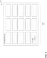
- Fig. 2 is a block diagram of an example layout of content on printed material 204, according to an embodiment.
- the printed material 204 may correspond to the printed material 104 of Fig. 1 , and the printed material 204 is described in the context of Fig. 1 for exemplary purposes.
- the printed material 204 is illustrated in Fig. 2 as comprising a label web sheet 202 having a plurality of lanes 206 that run across the direction of travel of the printed material 204 during production of the printed material 204, each lane 206 having a plurality of labels 208 that run along the direction of travel of the printed material 204 during production of the printed material 204.
- Each label 208 may include a mark 210.
- the mark 210 may be something that identifies a brand (e.g., a logo), something that bears information, such as a barcode a QR code, an expiration date, tracking information such as a serial number, etc., or a decoration.
- the configuration application 122 may be configured to determine a layout of the label web sheet on the printed material 204.
- the configuration application 122 may determine the following layout information: i) a number of lanes of labels on the web sheet, ii) a horizontal distance between corresponding left sides of two horizontally adjacent labels 208, iii) a vertical distance between corresponding bottom edges of two vertically adjacent labels, iv) a horizontal distance between a left edge of the web sheet and a center of a mark 210 in a left-most lane 206, and v) a vertical distance between a bottom edge of a label 208 and a center of a mark 210 on the label 208.
- an example user interface 300 may be provided by the imaging controller device 110 to obtain such layout information from a user.
- the user may enter the requested information via the user interface 300 that may be displayed to the user on a user device 142 or on a local display (not shown) that may be provided with the imaging system 102.
- the imaging controller device 110 may determine the specific layout of content on the printed material 104 by applying suitable image processing techniques to one or more sample images that may depict the content of the printed material 104.
- the imaging controller device 110 may acquire sample images of the printed material 204 that may be captured by the cameras 114 during a production run (e.g., during a sample production run or during an initial stage of a real production run) that may be performed by the production apparatus 106.
- the sample images may capture the entire area of printed material 204, for example.
- the imaging controller device 110 may process the sample images of the printed material 204 using suitable image processing and recognition techniques, for example to recognize that the printed material 204 is a label web sheet, to identify the labels 208 and the marks 210 on the label web sheet, and to determine the layout information (e.g., such as the layout information (i) - (v) described above or other suitable information) of the label web sheet.
- Fig. 4 is a block diagram of an example imaging controller device 410, according to an embodiment.
- the imaging controller device 410 corresponds to the imaging controller device 110 of Fig. 1 , and the imaging controller device 410 includes like-numbered elements with the imaging controller device 110 that are not discussed for brevity.
- the imaging controller device 410 includes an image acquisition controller 416, a processor 418, a memory 420 and an interface 444 that correspond, respectively, to the image acquisition controller 116, the processor 118, the memory 120, and the interface 144, in an embodiment.
- the memory 420 includes a configuration application 422 that corresponds to the configuration application 122 and an image processing application 424 that corresponds to the image processing application 124, in an embodiment.
- the memory 420 additionally includes a user interface module 426, a job training module 428 and a job management module 430.
- the job training module 428 may determine the specific layout of content on the printed material 104 by applying suitable image processing techniques to one or more sample images that may depict the content of the printed material 104.
- the job training module 428 may control operation of the optical device 108 during a production run (e.g., during a sample production run or during an initial stage of a real production run) that may be performed by the production apparatus 106, and may acquire sample images of the printed material 104 that may be captured by the cameras 114 during the production run performed by the production apparatus 106.
- the sample images may capture the entire area of printed material 104, for example.
- the job training module 428 may process the sample images of the printed material 104 using suitable image processing and recognition techniques, for example to recognize type of content on the printed material 104, and to identify locations of regions of interest on the printed material 104.
- the job training module 428 may be omitted from the imaging controller device 410, and the imaging controller device 410 may instead determine information descriptive of the layout of content on the printed material 104 based on user input.
- the job management module 430 may be configured to manage various configurations that the imaging controller device 410 may utilize, for example to operate during production runs with different printed material layouts that may be performed by the production apparatus 106.
- the job management module 430 may store optical system configuration profiles determined based on the different printed material layouts in a job configuration database 450 and may subsequently retrieve appropriate system configuration profiles to configure the imaging controller device 410 for operation during corresponding production runs that may be subsequently performed by the production apparatus 106.
- the user interface module 426 may provide various user interfaces for configuring the imaging controller device 410 and/or for monitoring operation of the imaging controller device 410.
- the user interface module 426 may provide a user interface for obtaining information descriptive of a layout of content on the printed material 104, such as, for example, the user interface 300 of Fig. 3 .
- the user interface module 426 may provide a user interface that allows the user to select or otherwise specify a particular production run so that a corresponding optical system configuration profile can be retrieved from the job configuration database 450.
- the user interface module 426 may provide a user interface for monitoring operation of the imaging controller device 410 during production of the printed material 104, such as monitoring progress of acquiring and processing images by the imaging controller device 410, informing users of any corrupted images acquired by the imaging controller device 410 during production of the printed material, providing alarms to the user, and the like.
- the image acquisition controller 416 may include or be directly or indirectly coupled to a trigger device 431 configured to provide control signals to the optical device 108 to control operation of the optical device 108 as described herein.
- the image acquisition controller 416 may be configured to utilize a camera software development kit (SDK) 432 to communicate with the cameras 114 of the optical device 108 and to acquired images captured by the cameras 114.
- SDK camera software development kit
- the image acquisition controller 416 may temporarily store the images acquired from the optical device 108 in an image database 434.
- the images may then be queued in an image pool 436 for processing by the processor 418.
- the processor 418 may process the images, and may temporarily store processed images and/or information (e.g., signatures) extracted from the images in a database 438, also referred to herein as a signature database 438.
- the processed images and/or the information extracted from the images may then be queued in a transfer queue 440 for subsequent transmission via the transfer interface 444.
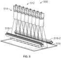
- Fig. 5 is a diagram of an example optical device 500 that may be utilized as the optical device 108 of Fig. 1 , according to an embodiment.
- the optical device 500 includes a imaging array 512 positioned over a hood 516.
- the imaging array 512 includes eight cameras 514 that are placed in a linear arrangement, with adjacent pairs of cameras 514 having overlapping fields of view, in the illustrated embodiment.
- the optical device 500 includes other suitable numbers of cameras 514 and/or the cameras 514 are arranged in other suitable manners.
- the optical device 500 additionally includes a plurality of light sources 518, including a first light source 518-1 and a second light source 518-2.
- the light sources 518 may be high intensity light emitting devices, such as strips of light emitting diodes (LEDs), for example.
- the light sources 518 may be positioned at 45 degree angles with respect to the surface of the hood 516, with light emitting surfaces pointing towards the fields of view of the cameras 514.
- the imaging controller device 110 control operation of the optical device 500 to trigger the cameras 514 to capture images of the printed material 104 and to acquire images captured by the cameras 514 as described herein. In an embodiment, each time the imaging controller device triggers the cameras 514 to capture an image, the imaging controller device 110 also triggers the light sources 518 to provide a high intensity flash during capture of the images by the cameras 514.
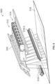
- Fig. 6 is a diagram of an example optical device 600 that may be utilized as the optical device 108 of Fig. 1 , according to another embodiment.
- the optical device 600 is generally the same as the optical device 500 of Fig. 5 , except that the optical device 600 includes a component 630 (e.g., a mirror) having a reflective surface that may be positioned to bend the optical paths of the cameras 514. Because the optical path of the cameras 514 is bent in the optical device 600, the height of the optical device 600 is reduced with respect to the height of the optical device 500, in at least some embodiments. The height reduction may allow use of the optical device 600 in tight areas where limited space may be available in the vicinity of the production apparatus 106, for example, in an embodiment.
- a component 630 e.g., a mirror
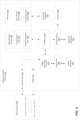
- Fig. 7 is a flow diagram of a method 700 for capturing images of printed material that may be implemented in the system of Fig. 1 , according to an embodiment.
- the method 700 may be implemented by the imaging controller device 110 (e.g., the processor 118) or the imaging controller device 410 (e.g., the processor 418), in example embodiments.
- the method 700 is described in the context of the imaging controller device 110 of Fig. 1 . In other embodiments, the method 700 is implemented by suitable devices different from the imaging controller device 110 of Fig. 1 .
- the imaging controller device 110 determines a layout of content on printed material to be produced during production of the printed material by a production apparatus, such as the production apparatus 106.
- the configuration application 122 determines the layout of the content on the printed material.
- the printed material corresponds to the printed material 104 produced by the production apparatus 106 of Fig. 1 .
- the layout of content on the printed material corresponds to the layout of the label web sheet 202 of Fig. 2 , and determination of the layout of the content on the printed material at block 702 is performed as described above with reference to Fig. 2 .
- determining the layout of content on printed material at block 702 comprises determining layouts of other suitable types of printed material and/or using other suitable determination techniques.
- the imaging controller device 110 determines, based on the layout of content on the printed material determined at block 702, an optical system configuration profile to be used for controlling an optical device (e.g., the optical device 108, the optical device 500, the optical device 600, or another suitable optical device) during production of the printed material by the production apparatus.
- determining the optical system configuration profile at block 704 may include selecting one or more cameras, among the plurality of cameras, for capturing images of one or more regions of interest on the printed material. The one or more cameras may be selected such that each region of interest among the one or more regions of interest fits, in its entirety, in a field of view of a particular camera among the one or more cameras. Determining the optical system configuration profile at block 704 may also determining a trigger interval for triggering the selected one or more cameras.
- the imaging controller device 110 controls operation of the optical device during production of the printed material by the production apparatus.
- Controlling operation of the optical device at block 706 includes triggering the one or more cameras selected at block 704 at times determined based on the trigger interval determined at block 704 to capture images of the one or more regions of interest on the printed material as the printed material moves in fields of view of the one or more cameras during production of the printed material, in an embodiment.
- the method 700 may additionally include processing the images captured during the production run, for example to generate signature and, in some embodiments HIDs, for marks that may be captured in the images.
- an example process for processing the images is described in more detail below with reference to Fig. 8 .
- other suitable processes are implemented to process the images.
- multiple cores and/or multi-threading techniques are utilized to perform parallel processing of the images.
- capturing each region of interest on the printed material 104 by a single camera 114 in a single image facilitates parallel processing of images by respective ones of multiple cores and/or using multiple threads because each core and/or thread may independently process a respective entire region of interest captured in a respective image.
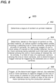
- Fig. 8 is a flow diagram of an example process 800 implemented to process captured images in the system of Fig. 1 , according to an embodiment.
- the image processing application 124 implements the process 800 to process images acquired by the image acquisition controller 116 from the optical device 108 during a production run performed by the production apparatus 106, in an example embodiment.
- the image processing application 124 may receive an image acquired by the image acquisition controller 116 and may use the acquired image to measure various characteristics of a mark that may be captured in the image. Measuring the various characteristics of the mark may result in a set of metrics that include data regarding artifacts of the mark (e.g., the mark 210).
- the set of metrics may be one of several sets of metrics that the image processing application 124 generates about the mark.
- the image processing application 124 may carry out the measurements in different locations on the mark. In doing so, the image processing application 124 can divide the mark into multiple subareas (e.g., in accordance with an industry standard).
- the image processing application 124 carries out measurements on all of or a subset of the total number of subareas (e.g., all of or a subset of the total number of cells) of the mark.
- characteristics of the mark that the imaging controller device 110 may measure include: (a) feature shape, (b) feature aspect ratios, (c) feature locations, (d) feature size, (e) feature contrast, (f) edge linearity, (g) region discontinuities, (h) extraneous marks, (i) printing defects, (j) color (e.g., lightness, hue, or both), (k) pigmentation, and (l) contrast variations.
- the image processing application 124 takes measurements on the same locations from mark to mark for each characteristic, but on different locations for different characteristics. For example, the image processing application 124 might measure the average pigmentation on a first set of locations of a mark, and on that same first set of locations for subsequent marks, but measure edge linearity on a second set of locations on the mark and on subsequent marks.
- the two sets of locations (for the different characteristics) may be said to be "different” if there is at least one location that is not common to both sets.
- the results of characteristic measuring by the image processing application 124 include a set of metrics. There may be one or more sets of metrics for each of the measured characteristics.
- the image processing application 124 may analyze the set of metrics measured at block 802 and, based on the analysis, may generate a signature that is based on the set of metrics. Because the set of metrics includes data regarding an artifact (or multiple artifacts) of the mark, the signature will be indirectly based on the artifact. If the mark carries data (as in the case of a 2D barcode), the image processing application 124 may also include such data as part of the signature. Put another way, in some embodiments, the signature may be based on both artifacts of the mark and on the data carried by the mark.
- the image processing application 124 in order to generate the signature, for each measured characteristic of the mark, the image processing application 124 ranks the metrics associated with the characteristic by magnitude and uses only those metrics that reach a predetermined threshold as part of the signature. For example, the image processing application 124 might refrain from ranking those metrics that are below the predetermined threshold. In an embodiment, there is a different predetermined threshold for each characteristic being measured. One or more of the predetermined thresholds may be based on a noise threshold and on the resolution of the camera 114 that was used to capture the image.
- the image processing application 124 obtains one hundred data points for each characteristic and collects six groups of measurements: one set of measurements for pigmentation, one set of measurements for deviation from a best-fit grid, one set of measurements for extraneous markings or voids, and three separate sets of measurements for edge linearity.
- the image processing application 124 may group together metrics that are below the predetermined threshold regardless of their respective locations (i.e., regardless of their locations on the mark). Also, the image processing application 124 may order the metrics (e.g., by magnitude) in each characteristic category as part of the ranking process. Similarly, the image processing application 124 might simply discount the metrics that are below the predetermined threshold. Also, the process of ranking may simply constitute separating metrics that are above the threshold from those that are below the threshold.
- the image processing application 124 orders the measured characteristics according to how sensitive the characteristics are to image resolution issues. For example, if the cameras 114 of the optical device 108 do not have the capability to capture an image in sufficiently high resolution, it might be difficult for the image processing application 124 to identify non-linearities of edges. However, the image processing application 124 may have no problem identifying deviations in pigmentation. Thus, the image processing application 124 might, on this basis, prioritize pigmentation over edge non-linearities. According to an embodiment, image processing application 124 orders the measured characteristics in reverse order of resolution-dependence as follows: subarea pigmentation, subarea position bias, locations of voids or extraneous markings, and edge non-linearities.
- the image processing application 124 weights the measured characteristics of the mark based on one or more of the resolution of the cameras 114 of the optical device 108 and the resolution of the captured image of the mark. For example, if the resolution of the cameras 114 is low, then the image processing application 124 may give more weight to the average pigmentation of the various subareas of the mark. If the resolution of cameras 114 is high, then the image processing application 124 may give measurements of the edge irregularities of various subareas higher weight than other characteristics. If the mark includes error-correcting information, such as that set forth by ISO/IEC 16022, then the image processing application 124 may use the error-correcting information to weight the measured characteristics. For example, the image processing application 124 could read the error-correcting information, use the error-correcting information to determine which subareas of the mark have errors, and under-weight the measured characteristics of such subareas.
- error-correcting information such as that set forth by ISO/IEC 16022
- the image processing application 124 may use location identifiers corresponding to a subset of the metrics of the signature to derive a hash identifier (HID).
- the image processing application 124 uses index numbers corresponding to a subset of the highest-magnitude metrics of the signature to derive an HID.
- the image processing application 124 may, in deriving the HID, use index numbers corresponding to a subset of each set of metrics as a block within an overall HID.
- the imaging controller device 110 may transmit the signature and the HID via the interface 144 and the communication network 150 to the server device 140 and/or the database 152 such that the HID is associated with the signature.
- the HID can also be used to look up the signature (e.g., the server device 140 uses a database program to set the HID as an index key for the signature).
- FIG. 9 is a block diagram of a computer system 900 suitable for implementing one or more components of the system of FIG. 1 , according to an embodiment.
- the computer system 900 may include at least one processor 902 and at least one memory 904.
- the computer system 900 may also include a bus (not shown) or other communication mechanism for communicating information data, signals, and information between various components of computer system 900.
- Components may include an input component 910 that processes a user action, such as selecting keys from a keypad/keyboard, selecting one or more buttons or links, etc., and sends a corresponding signal to the at least one processor 902.
- Components may also include an output component, such as a display, 911 that may display, for example, results of operations performed by the at least one processor 902.
- a transceiver or network interface 906 may transmit and receive signals between the computer system 900 and other devices, such as user devices that may utilize results of processes implemented by the computer system 900.
- the transmission is wireless, although other transmission mediums and methods may also be suitable.
- the at least one processor 902 which can be a micro-controller, digital signal processor (DSP), or other processing component, processes these various signals, such as for display on the computer system 900 or transmission to other devices via a communication link 918.
- the at least one processor 902 may also control transmission of information, such as cookies or IP addresses, to other devices.
- the at least one processor 902 may execute computer readable instructions stored in the memory 904.
- the computer readable instructions when executed by the at least one processor 902, may cause the at least one processor 902 to implement processes associated with video frame processing and/or recognition of a subject based on a plurality of video frames.
- Components of the computer system 900 may also include at least one static storage component 916 (e.g., ROM) and/or at least one disk drive 917.
- Computer system 900 may perform specific operations by processor 912 and other components by executing one or more sequences of instructions contained in system the memory 904.
- Logic may be encoded in a computer readable medium, which may refer to any medium that participates in providing instructions to the at least one processor 902 for execution. Such a medium may take many forms, including but not limited to, non-transitory media, non-volatile media, or volatile media, and transmission media.
- non-volatile media includes optical or magnetic disks
- volatile media includes dynamic memory, such as system memory component 914
- transmission media includes coaxial cables, copper wire, and fiber optics.
- the logic is encoded in non-transitory computer readable medium.
- transmission media may take the form of acoustic or light waves, such as those generated during radio wave, optical, and infrared data communications.
- various embodiments provided by the present disclosure may be implemented using hardware, software, or combinations of hardware and software.
- the various hardware components and/or software components set forth herein may be combined into composite components comprising software, hardware, and/or both without departing from the spirit of the present disclosure.
- the various hardware components and/or software components set forth herein may be separated into sub-components comprising software, hardware, or both without departing from the scope of the present disclosure.
- software components may be implemented as hardware components and vice-versa.
- Software in accordance with the present disclosure, such as program code and/or data, may be stored on one or more computer readable mediums. It is also contemplated that software identified herein may be implemented using one or more general purpose or specific purpose computers and/or computer systems, networked and/or otherwise. Where applicable, the ordering of various steps described herein may be changed, combined into composite steps, and/or separated into sub-steps to provide features described herein.
- the hardware may comprise one or more of discrete components, an integrated circuit, an application-specific integrated circuit (ASIC), a programmable logic device (PLD), etc.
- ASIC application-specific integrated circuit
- PLD programmable logic device
- modules While various operations have been described herein in terms of “modules” or “components,” it is noted that that terms are not limited to single units or functions. Moreover, functionality attributed to some of the modules or components described herein may be combined and attributed to fewer modules or components. Further still, while the present disclosure refers to specific examples, those examples are intended to be illustrative only, and are not intended to be limiting in scope. It will be apparent to those of ordinary skill in the art that changes, additions and/or deletions may be made to the disclosed embodiments without departing from the scope of the appended claims.
Landscapes
- Engineering & Computer Science (AREA)
- Multimedia (AREA)
- Signal Processing (AREA)
- General Engineering & Computer Science (AREA)
- Computing Systems (AREA)
- Computer Vision & Pattern Recognition (AREA)
- Human Computer Interaction (AREA)
- Investigating Materials By The Use Of Optical Means Adapted For Particular Applications (AREA)
- Ink Jet (AREA)
- Facsimile Scanning Arrangements (AREA)
- Studio Devices (AREA)
Claims (16)
- System zum Aufnehmen von Bildern während Herstellung von Druckmaterial, wobei das System umfasst:
eine optische Vorrichtung, die eine Vielzahl von in einem Array angeordneten Kameras umfasst, wobei benachbarte Kamerapaare in dem Array überlappende Sichtfelder aufweisen; und gekennzeichnet durch:
eine Bildgebungssteuervorrichtung, die konfiguriert ist zum:Bestimmen eines Inhaltslayouts auf Druckmaterial,Bestimmen eines optischen Systemkonfigurationsprofils basierend auf dem Inhaltslayout auf dem Druckmaterial, beinhaltend i) Auswählen einer oder mehrerer Kameras aus der Vielzahl von Kameras zum Aufnehmen von Bildern eines oder mehrerer Interessenbereiche auf dem Druckmaterial, wobei die eine oder mehreren Kameras so ausgewählt werden, dass jeder Interessenbereich aus dem einen oder den mehreren Interessenbereichen in seiner Gesamtheit in ein Sichtfeld einer bestimmten Kamera aus der einen oder den mehreren Kameras passt, und ii) Bestimmen eines Auslöseintervalls zum Auslösen der ausgewählten einen oder mehreren Kameras, undAuslösen der ausgewählten einen oder mehreren Kameras zu Zeiten, die basierend auf dem Auslöseintervall bestimmt werden, um Bilder des einen oder der mehreren Interessenbereiche auf dem Druckmaterial aufzunehmen, während sich das Druckmaterial während Herstellung des Druckmaterials in Sichtfeldern der einen oder mehreren Kameras bewegt. - System nach Anspruch 1, wobei die Bildgebungssteuervorrichtung konfiguriert ist, das Inhaltslayout auf dem Druckmaterial basierend auf Benutzereingaben zu bestimmen.
- System nach Anspruch 1, wobei die Bildgebungssteuervorrichtung konfiguriert ist, das Inhaltslayout auf dem Druckmaterial basierend auf einer Verarbeitung eines oder mehrerer Beispielbilder des Druckmaterials zu bestimmen.
- System nach Anspruch 1, wobei die Vielzahl von Kameras in einem linearen Kameraarray mit überlappenden Sichtfeldern angeordnet ist.
- System nach Anspruch 1, wobeidie optische Vorrichtung weiter eine oder mehrere Lichtemissionsvorrichtungen umfasst unddie Bildgebungssteuervorrichtung weiter konfiguriert ist, im bestimmten Auslöseintervall die eine oder mehreren Lichtemissionsvorrichtungen auszulösen, um während Aufnahme der Bilder Lichtblitze zu erzeugen.
- System nach Anspruch 1, wobei die optische Vorrichtung weiter eine reflektierende Oberfläche umfasst, die konfiguriert ist, optische Pfade der Vielzahl von Kameras zu krümmen, um eine Höhenabmessung der optischen Vorrichtung zu verringern.
- System nach Anspruch 1, wobei die Bildgebungssteuervorrichtung weiter konfiguriert ist zumEmpfangen von Sensorsignalen, die von einem Sensor erzeugt werden, wobei die Sensorsignale Referenzpunkte auf dem Druckmaterial während Herstellung des Druckmaterials angeben,Empfangen von Encodersignalen, die von einem Encoder erzeugt werden, wobei die Encodersignale Bewegung des Druckmaterials während Herstellung des Druckmaterials verfolgen, undAuslösen der ausgewählten einen oder mehreren Kameras zu Zeiten, die weiter unter Verwendung der Sensorsignale und der Bewegungssignale bestimmt werden.
- System nach Anspruch 1, wobei die Bildgebungssteuervorrichtung einen oder mehrere Prozessoren umfasst, die zum Verarbeiten der aufgenommenen Bilder konfiguriert sind.
- System nach Anspruch 8, wobei der eine oder die mehreren Prozessoren konfiguriert sind, die aufgenommenen Bilder zu verarbeiten, um Defekte zur Qualitätskontrolle in der Herstellung des Druckmaterials zu erkennen.
- System nach Anspruch 8, wobei:
der eine oder die mehreren Interessenbereiche auf dem Druckmaterial gedruckte Markierungen beinhalten und
der eine oder die mehreren Prozessoren konfiguriert sind, die aufgenommenen Bilder zu verarbeiten, um elektronische Signaturen für die gedruckten Markierungen zu erzeugen, wobei die elektronischen Signaturen anschließend zur Authentifizierung der gedruckten Markierungen verwendet werden sollen. - System nach Anspruch 9, wobei die Bildgebungssteuervorrichtung weiter konfiguriert ist, über ein Netzwerk eines oder beide von i) den aufgenommenen Bildern und ii) elektronischen Signaturen, die basierend auf den aufgenommenen Bildern erzeugt werden, an eine Servervorrichtung zu übertragen.
- System nach Anspruch 1, wobei die Bildgebungssteuervorrichtung weiter konfiguriert ist, das optische Systemkonfigurationsprofil zur Verwendung während Herstellung des Druckmaterials in einem Speicher zu speichern.
- System nach Anspruch 12, wobei die Bildgebungssteuervorrichtung weiter konfiguriert ist zumAuswählen des optischen Systemkonfigurationsprofils aus einer Vielzahl von im Speicher gespeicherten optischen Systemkonfigurationsprofilen und,als Reaktion auf Auswählen des optischen Systemkonfigurationsprofils, Abrufen des optischen Systemkonfigurationsprofils aus dem Speicher zur Verwendung während Herstellung des Druckmaterials.
- Verfahren zum Aufnehmen von Bildern von Druckmaterial durch eine optische Vorrichtung, die mit einer Vielzahl von in einem Array angeordneten Kameras ausgestattet ist, wobei benachbarte Kamerapaare in dem Array überlappende Sichtfelder aufweisen, wobei das Verfahren umfasstBestimmen eines Inhaltslayouts auf Druckmaterial mit einem Prozessor einer Bildgebungssteuervorrichtung;Bestimmen eines optischen Systemkonfigurationsprofils mit dem Prozessor der Bildgebungssteuervorrichtung basierend auf dem Inhaltslayout auf dem Druckmaterial, beinhaltend i) Auswählen einer oder mehrerer Kameras aus der Vielzahl von Kameras zum Aufnehmen von Bildern eines oder mehrerer Interessenbereiche auf dem Druckmaterial, wobei die eine oder mehreren Kameras so ausgewählt werden, dass jeder Interessenbereich aus dem einen oder den mehreren Interessenbereichen in seiner Gesamtheit in ein Sichtfeld einer bestimmten Kamera aus der einen oder den mehreren Kameras passt, und ii) Bestimmen eines Auslöseintervalls zum Auslösen der ausgewählten einen oder mehreren Kameras; undAuslösen der ausgewählten einen oder mehreren Kameras mit der Bildgebungssteuervorrichtung zu Zeiten, die basierend auf dem Auslöseintervall bestimmt werden, um Bilder des einen oder der mehreren Interessenbereiche auf dem Druckmaterial aufzunehmen, während sich das Druckmaterial während Herstellung des Druckmaterials in Sichtfeldern der einen oder mehreren Kameras bewegt.
- Verfahren nach Anspruch 14, wobei:die optische Vorrichtung weiter eine oder mehrere Lichtemissionsvorrichtungen umfasst unddas Verfahren weiter Auslösen der einen oder mehreren Lichtemissionsvorrichtungen mit der Bildgebungssteuervorrichtung im bestimmten Auslöseintervall umfasst, um während der Aufnahme der Bilder Lichtblitze zu erzeugen.
- Verfahren nach Anspruch 14, wobei:das Verfahren weiter umfasstEmpfangen von Sensorsignalen, die Referenzpunkte auf dem Druckmaterial angeben, am Prozessor der Bildgebungssteuervorrichtung während Herstellung des Druckmaterials,Empfangen von Encodersignalen, die Bewegung des Druckmaterials während Herstellung des Druckmaterials verfolgen, am Prozessor der Bildgebungssteuervorrichtung undAuslösen der ausgewählten einen oder mehreren Kameras Auslösen der ausgewählten einen oder mehreren Kameras zu Zeiten umfasst, die unter Verwendung der Sensorsignale und Encodersignale bestimmt werden.
Priority Applications (1)
| Application Number | Priority Date | Filing Date | Title |
|---|---|---|---|
| EP25162457.3A EP4586601A1 (de) | 2020-06-18 | 2021-06-16 | Verfahren und system zur abbildung von sich bewegenden druckmaterialien |
Applications Claiming Priority (2)
| Application Number | Priority Date | Filing Date | Title |
|---|---|---|---|
| US202063040898P | 2020-06-18 | 2020-06-18 | |
| PCT/US2021/037629 WO2021257704A1 (en) | 2020-06-18 | 2021-06-16 | Methods and system for imaging of moving printed materials |
Related Child Applications (1)
| Application Number | Title | Priority Date | Filing Date |
|---|---|---|---|
| EP25162457.3A Division EP4586601A1 (de) | 2020-06-18 | 2021-06-16 | Verfahren und system zur abbildung von sich bewegenden druckmaterialien |
Publications (3)
| Publication Number | Publication Date |
|---|---|
| EP4168926A1 EP4168926A1 (de) | 2023-04-26 |
| EP4168926A4 EP4168926A4 (de) | 2024-04-17 |
| EP4168926B1 true EP4168926B1 (de) | 2025-03-12 |
Family
ID=79268376
Family Applications (2)
| Application Number | Title | Priority Date | Filing Date |
|---|---|---|---|
| EP21826818.3A Active EP4168926B1 (de) | 2020-06-18 | 2021-06-16 | Verfahren und system zur abbildung von sich bewegenden druckmaterialien |
| EP25162457.3A Pending EP4586601A1 (de) | 2020-06-18 | 2021-06-16 | Verfahren und system zur abbildung von sich bewegenden druckmaterialien |
Family Applications After (1)
| Application Number | Title | Priority Date | Filing Date |
|---|---|---|---|
| EP25162457.3A Pending EP4586601A1 (de) | 2020-06-18 | 2021-06-16 | Verfahren und system zur abbildung von sich bewegenden druckmaterialien |
Country Status (9)
| Country | Link |
|---|---|
| US (2) | US11811983B2 (de) |
| EP (2) | EP4168926B1 (de) |
| JP (2) | JP7531628B2 (de) |
| CN (1) | CN116134443A (de) |
| CA (1) | CA3183090A1 (de) |
| DK (1) | DK4168926T3 (de) |
| ES (1) | ES3023387T3 (de) |
| MX (1) | MX2022016350A (de) |
| WO (1) | WO2021257704A1 (de) |
Families Citing this family (3)
| Publication number | Priority date | Publication date | Assignee | Title |
|---|---|---|---|---|
| JP2023140699A (ja) * | 2022-03-23 | 2023-10-05 | 株式会社リコー | 情報処理システム、情報処理方法、プログラム及び情報処理装置 |
| JP2024035440A (ja) * | 2022-09-02 | 2024-03-14 | 株式会社リコー | 情報処理システム、管理方法、情報処理装置及びプログラム |
| WO2025054534A1 (en) * | 2023-09-08 | 2025-03-13 | Sys-Tech Solutions, Inc. | Edge-based electronic signature determination for genuine product marks using parallel processing |
Family Cites Families (22)
| Publication number | Priority date | Publication date | Assignee | Title |
|---|---|---|---|---|
| DE3821572A1 (de) | 1988-06-25 | 1989-12-28 | Graetz Nokia Gmbh | Fernbedienungsanordnung |
| JPH07200792A (ja) * | 1993-12-29 | 1995-08-04 | Toppan Printing Co Ltd | 印刷物検査装置 |
| JP3770649B2 (ja) | 1996-05-09 | 2006-04-26 | 大日本印刷株式会社 | 印刷物検査装置 |
| AUPQ439299A0 (en) | 1999-12-01 | 1999-12-23 | Silverbrook Research Pty Ltd | Interface system |
| DE102004003613B4 (de) | 2004-01-25 | 2015-01-08 | grapho metronic Meß- und Regeltechnik GmbH | Vorrichtung und Erfassung eines Bildes von einem vorbestimmten Ausschnitt eines in Bewegung befindlichen Druckerzeugnisses |
| US7889381B2 (en) * | 2004-05-28 | 2011-02-15 | Fujifilm Corporation | Photo service system |
| JP2008014857A (ja) * | 2006-07-07 | 2008-01-24 | Fujitsu Ltd | プリント板の検査用座標取得装置、検査用座標取得方法、及び検査用座標取得プログラム |
| JP2008310415A (ja) * | 2007-06-12 | 2008-12-25 | Nireco Corp | 画像処理装置 |
| US7843611B2 (en) * | 2007-07-18 | 2010-11-30 | Kuwait University | High speed flatbed scanner comprising digital image-capture module with two-dimensional optical image photo-sensor or digital camera |
| JP2010286256A (ja) | 2009-06-09 | 2010-12-24 | Jfe Techno Research Corp | 印刷物の検査方法 |
| JP2011158421A (ja) * | 2010-02-03 | 2011-08-18 | Toppan Printing Co Ltd | 印刷物検査装置 |
| US9007432B2 (en) | 2010-12-16 | 2015-04-14 | The Massachusetts Institute Of Technology | Imaging systems and methods for immersive surveillance |
| JP5914075B2 (ja) * | 2012-03-21 | 2016-05-11 | ヤマハ発動機株式会社 | プリント配線板用撮像装置、表面実装機および実装システム |
| JP5989128B2 (ja) * | 2012-10-30 | 2016-09-07 | 三菱電機株式会社 | 印刷物識別装置及び印刷物識別システム |
| JP6476658B2 (ja) * | 2013-09-11 | 2019-03-06 | ソニー株式会社 | 画像処理装置および方法 |
| US9519942B2 (en) | 2015-02-17 | 2016-12-13 | Sys-Tech Solutions, Inc. | Methods and a computing device for determining whether a mark is genuine |
| US9940572B2 (en) | 2015-02-17 | 2018-04-10 | Sys-Tech Solutions, Inc. | Methods and a computing device for determining whether a mark is genuine |
| EP3208782B1 (de) | 2016-02-22 | 2022-10-19 | Wincor Nixdorf International GmbH | Leergutrücknahmevorrichtung |
| US10744756B2 (en) * | 2017-03-21 | 2020-08-18 | Ricoh Company, Ltd. | Conveyance device, conveyance system, and head unit control method |
| US11042146B2 (en) * | 2017-11-17 | 2021-06-22 | Kodak Alaris Inc. | Automated 360-degree dense point object inspection |
| EP3599094B1 (de) * | 2018-07-24 | 2024-05-08 | Dover Europe Sàrl | System und verfahren zur visuellen verifizierung |
| JP7540878B2 (ja) * | 2019-01-10 | 2024-08-27 | 株式会社ダイフク | 物品搬送装置 |
-
2021
- 2021-06-16 EP EP21826818.3A patent/EP4168926B1/de active Active
- 2021-06-16 EP EP25162457.3A patent/EP4586601A1/de active Pending
- 2021-06-16 CN CN202180056470.8A patent/CN116134443A/zh active Pending
- 2021-06-16 CA CA3183090A patent/CA3183090A1/en active Pending
- 2021-06-16 DK DK21826818.3T patent/DK4168926T3/da active
- 2021-06-16 MX MX2022016350A patent/MX2022016350A/es unknown
- 2021-06-16 WO PCT/US2021/037629 patent/WO2021257704A1/en not_active Ceased
- 2021-06-16 JP JP2022577337A patent/JP7531628B2/ja active Active
- 2021-06-16 ES ES21826818T patent/ES3023387T3/es active Active
- 2021-06-16 US US18/010,565 patent/US11811983B2/en active Active
-
2023
- 2023-11-03 US US18/386,770 patent/US12395593B2/en active Active
-
2024
- 2024-07-30 JP JP2024123681A patent/JP2024163115A/ja active Pending
Also Published As
| Publication number | Publication date |
|---|---|
| WO2021257704A1 (en) | 2021-12-23 |
| DK4168926T3 (da) | 2025-05-19 |
| US20240064245A1 (en) | 2024-02-22 |
| EP4168926A4 (de) | 2024-04-17 |
| US12395593B2 (en) | 2025-08-19 |
| EP4586601A1 (de) | 2025-07-16 |
| JP2024163115A (ja) | 2024-11-21 |
| EP4168926A1 (de) | 2023-04-26 |
| MX2022016350A (es) | 2023-03-06 |
| JP7531628B2 (ja) | 2024-08-09 |
| JP2023530979A (ja) | 2023-07-20 |
| ES3023387T3 (en) | 2025-05-30 |
| US11811983B2 (en) | 2023-11-07 |
| CN116134443A (zh) | 2023-05-16 |
| US20230231955A1 (en) | 2023-07-20 |
| CA3183090A1 (en) | 2021-12-23 |
Similar Documents
| Publication | Publication Date | Title |
|---|---|---|
| US12395593B2 (en) | Methods and system for imaging of moving printed materials by an optical device with parallel processing | |
| US20250343866A1 (en) | Methods, apparatuses, and systems for detecting printing defects and contaminated components of a printer | |
| EP3937080B1 (de) | Verfahren und rechnervorrichtung zur bestimmung der echtheit einer markierung | |
| US8885048B2 (en) | Computer vision and radio frequency identification technology based book enrolment management apparatus | |
| KR101227298B1 (ko) | 물질 웹에 결함을 자동 마킹하기 위한 장치 및 방법 | |
| US9286501B2 (en) | Method and device for identifying a two-dimensional barcode | |
| US9652652B2 (en) | Method and device for identifying a two-dimensional barcode | |
| CN107004110A (zh) | 用于验证标记的真实性的方法和系统 | |
| CN119688732B (zh) | 一种印刷品质量检测方法、装置及存储介质 | |
| EP4535157A1 (de) | Computerimplementiertes verfahren zur erzeugung von arbeitsparametern einer druckvorrichtung, system, computerprogramm und computerlesbares medium dafür | |
| JP2004094442A (ja) | 枚数計測方法および枚数計測装置 | |
| CN118688119A (zh) | 一种缺陷检测系统及其缺陷检测方法 | |
| CN119623498A (zh) | 一种读码方法、装置、设备、系统及存储介质 | |
| CN120931491A (zh) | 基于超分辨率视觉的整包即开型彩票自动分拣复核方法及系统 | |
| CN122003659A (zh) | 用于生成印刷设备的工作参数的计算机实施的方法、系统、计算机程序及其计算机可读介质 | |
| CN112163800A (zh) | 一种视觉检测工具的管理方法和装置 |
Legal Events
| Date | Code | Title | Description |
|---|---|---|---|
| STAA | Information on the status of an ep patent application or granted ep patent |
Free format text: STATUS: THE INTERNATIONAL PUBLICATION HAS BEEN MADE |
|
| PUAI | Public reference made under article 153(3) epc to a published international application that has entered the european phase |
Free format text: ORIGINAL CODE: 0009012 |
|
| STAA | Information on the status of an ep patent application or granted ep patent |
Free format text: STATUS: REQUEST FOR EXAMINATION WAS MADE |
|
| 17P | Request for examination filed |
Effective date: 20230116 |
|
| AK | Designated contracting states |
Kind code of ref document: A1 Designated state(s): AL AT BE BG CH CY CZ DE DK EE ES FI FR GB GR HR HU IE IS IT LI LT LU LV MC MK MT NL NO PL PT RO RS SE SI SK SM TR |
|
| P01 | Opt-out of the competence of the unified patent court (upc) registered |
Effective date: 20230530 |
|
| DAV | Request for validation of the european patent (deleted) | ||
| DAX | Request for extension of the european patent (deleted) | ||
| A4 | Supplementary search report drawn up and despatched |
Effective date: 20240320 |
|
| RIC1 | Information provided on ipc code assigned before grant |
Ipc: G06K 5/04 20060101ALI20240314BHEP Ipc: G06K 5/02 20060101AFI20240314BHEP |
|
| GRAP | Despatch of communication of intention to grant a patent |
Free format text: ORIGINAL CODE: EPIDOSNIGR1 |
|
| STAA | Information on the status of an ep patent application or granted ep patent |
Free format text: STATUS: GRANT OF PATENT IS INTENDED |
|
| INTG | Intention to grant announced |
Effective date: 20241004 |
|
| GRAS | Grant fee paid |
Free format text: ORIGINAL CODE: EPIDOSNIGR3 |
|
| GRAA | (expected) grant |
Free format text: ORIGINAL CODE: 0009210 |
|
| STAA | Information on the status of an ep patent application or granted ep patent |
Free format text: STATUS: THE PATENT HAS BEEN GRANTED |
|
| AK | Designated contracting states |
Kind code of ref document: B1 Designated state(s): AL AT BE BG CH CY CZ DE DK EE ES FI FR GB GR HR HU IE IS IT LI LT LU LV MC MK MT NL NO PL PT RO RS SE SI SK SM TR |
|
| REG | Reference to a national code |
Ref country code: GB Ref legal event code: FG4D |
|
| REG | Reference to a national code |
Ref country code: CH Ref legal event code: EP |
|
| REG | Reference to a national code |
Ref country code: DE Ref legal event code: R096 Ref document number: 602021027607 Country of ref document: DE |
|
| REG | Reference to a national code |
Ref country code: IE Ref legal event code: FG4D |
|
| REG | Reference to a national code |
Ref country code: DK Ref legal event code: T3 Effective date: 20250515 |
|
| REG | Reference to a national code |
Ref country code: NL Ref legal event code: FP |
|
| REG | Reference to a national code |
Ref country code: ES Ref legal event code: FG2A Ref document number: 3023387 Country of ref document: ES Kind code of ref document: T3 Effective date: 20250530 |
|
| REG | Reference to a national code |
Ref country code: SE Ref legal event code: TRGR |
|
| PG25 | Lapsed in a contracting state [announced via postgrant information from national office to epo] |
Ref country code: RS Free format text: LAPSE BECAUSE OF FAILURE TO SUBMIT A TRANSLATION OF THE DESCRIPTION OR TO PAY THE FEE WITHIN THE PRESCRIBED TIME-LIMIT Effective date: 20250612 |
|
| PG25 | Lapsed in a contracting state [announced via postgrant information from national office to epo] |
Ref country code: FI Free format text: LAPSE BECAUSE OF FAILURE TO SUBMIT A TRANSLATION OF THE DESCRIPTION OR TO PAY THE FEE WITHIN THE PRESCRIBED TIME-LIMIT Effective date: 20250312 |
|
| PGFP | Annual fee paid to national office [announced via postgrant information from national office to epo] |
Ref country code: DE Payment date: 20250618 Year of fee payment: 5 |
|
| PGFP | Annual fee paid to national office [announced via postgrant information from national office to epo] |
Ref country code: GB Payment date: 20250619 Year of fee payment: 5 Ref country code: DK Payment date: 20250630 Year of fee payment: 5 |
|
| REG | Reference to a national code |
Ref country code: LT Ref legal event code: MG9D |
|
| PG25 | Lapsed in a contracting state [announced via postgrant information from national office to epo] |
Ref country code: NO Free format text: LAPSE BECAUSE OF FAILURE TO SUBMIT A TRANSLATION OF THE DESCRIPTION OR TO PAY THE FEE WITHIN THE PRESCRIBED TIME-LIMIT Effective date: 20250612 |
|
| PGFP | Annual fee paid to national office [announced via postgrant information from national office to epo] |
Ref country code: NL Payment date: 20250627 Year of fee payment: 5 Ref country code: BE Payment date: 20250626 Year of fee payment: 5 |
|
| PG25 | Lapsed in a contracting state [announced via postgrant information from national office to epo] |
Ref country code: HR Free format text: LAPSE BECAUSE OF FAILURE TO SUBMIT A TRANSLATION OF THE DESCRIPTION OR TO PAY THE FEE WITHIN THE PRESCRIBED TIME-LIMIT Effective date: 20250312 |
|
| PG25 | Lapsed in a contracting state [announced via postgrant information from national office to epo] |
Ref country code: LV Free format text: LAPSE BECAUSE OF FAILURE TO SUBMIT A TRANSLATION OF THE DESCRIPTION OR TO PAY THE FEE WITHIN THE PRESCRIBED TIME-LIMIT Effective date: 20250312 |
|
| PGFP | Annual fee paid to national office [announced via postgrant information from national office to epo] |
Ref country code: FR Payment date: 20250623 Year of fee payment: 5 |
|
| PG25 | Lapsed in a contracting state [announced via postgrant information from national office to epo] |
Ref country code: BG Free format text: LAPSE BECAUSE OF FAILURE TO SUBMIT A TRANSLATION OF THE DESCRIPTION OR TO PAY THE FEE WITHIN THE PRESCRIBED TIME-LIMIT Effective date: 20250312 Ref country code: GR Free format text: LAPSE BECAUSE OF FAILURE TO SUBMIT A TRANSLATION OF THE DESCRIPTION OR TO PAY THE FEE WITHIN THE PRESCRIBED TIME-LIMIT Effective date: 20250613 |
|
| PGFP | Annual fee paid to national office [announced via postgrant information from national office to epo] |
Ref country code: AT Payment date: 20250721 Year of fee payment: 5 |
|
| PGFP | Annual fee paid to national office [announced via postgrant information from national office to epo] |
Ref country code: IE Payment date: 20250624 Year of fee payment: 5 |
|
| PGFP | Annual fee paid to national office [announced via postgrant information from national office to epo] |
Ref country code: SE Payment date: 20250626 Year of fee payment: 5 |
|
| PG25 | Lapsed in a contracting state [announced via postgrant information from national office to epo] |
Ref country code: SM Free format text: LAPSE BECAUSE OF FAILURE TO SUBMIT A TRANSLATION OF THE DESCRIPTION OR TO PAY THE FEE WITHIN THE PRESCRIBED TIME-LIMIT Effective date: 20250312 |
|
| PG25 | Lapsed in a contracting state [announced via postgrant information from national office to epo] |
Ref country code: PT Free format text: LAPSE BECAUSE OF FAILURE TO SUBMIT A TRANSLATION OF THE DESCRIPTION OR TO PAY THE FEE WITHIN THE PRESCRIBED TIME-LIMIT Effective date: 20250714 |
|
| PGFP | Annual fee paid to national office [announced via postgrant information from national office to epo] |
Ref country code: ES Payment date: 20250703 Year of fee payment: 5 |
|
| PG25 | Lapsed in a contracting state [announced via postgrant information from national office to epo] |
Ref country code: IT Free format text: LAPSE BECAUSE OF FAILURE TO SUBMIT A TRANSLATION OF THE DESCRIPTION OR TO PAY THE FEE WITHIN THE PRESCRIBED TIME-LIMIT Effective date: 20250312 Ref country code: PL Free format text: LAPSE BECAUSE OF FAILURE TO SUBMIT A TRANSLATION OF THE DESCRIPTION OR TO PAY THE FEE WITHIN THE PRESCRIBED TIME-LIMIT Effective date: 20250312 |
|
| PGFP | Annual fee paid to national office [announced via postgrant information from national office to epo] |
Ref country code: CH Payment date: 20250701 Year of fee payment: 5 |
|
| PG25 | Lapsed in a contracting state [announced via postgrant information from national office to epo] |
Ref country code: CZ Free format text: LAPSE BECAUSE OF FAILURE TO SUBMIT A TRANSLATION OF THE DESCRIPTION OR TO PAY THE FEE WITHIN THE PRESCRIBED TIME-LIMIT Effective date: 20250312 Ref country code: EE Free format text: LAPSE BECAUSE OF FAILURE TO SUBMIT A TRANSLATION OF THE DESCRIPTION OR TO PAY THE FEE WITHIN THE PRESCRIBED TIME-LIMIT Effective date: 20250312 |
|
| PG25 | Lapsed in a contracting state [announced via postgrant information from national office to epo] |
Ref country code: RO Free format text: LAPSE BECAUSE OF FAILURE TO SUBMIT A TRANSLATION OF THE DESCRIPTION OR TO PAY THE FEE WITHIN THE PRESCRIBED TIME-LIMIT Effective date: 20250312 |
|
| PG25 | Lapsed in a contracting state [announced via postgrant information from national office to epo] |
Ref country code: SK Free format text: LAPSE BECAUSE OF FAILURE TO SUBMIT A TRANSLATION OF THE DESCRIPTION OR TO PAY THE FEE WITHIN THE PRESCRIBED TIME-LIMIT Effective date: 20250312 |
|
| PG25 | Lapsed in a contracting state [announced via postgrant information from national office to epo] |
Ref country code: IS Free format text: LAPSE BECAUSE OF FAILURE TO SUBMIT A TRANSLATION OF THE DESCRIPTION OR TO PAY THE FEE WITHIN THE PRESCRIBED TIME-LIMIT Effective date: 20250712 |
|
| REG | Reference to a national code |
Ref country code: DE Ref legal event code: R097 Ref document number: 602021027607 Country of ref document: DE |
|
| PLBE | No opposition filed within time limit |
Free format text: ORIGINAL CODE: 0009261 |
|
| STAA | Information on the status of an ep patent application or granted ep patent |
Free format text: STATUS: NO OPPOSITION FILED WITHIN TIME LIMIT |
|
| REG | Reference to a national code |
Ref country code: CH Ref legal event code: L10 Free format text: ST27 STATUS EVENT CODE: U-0-0-L10-L00 (AS PROVIDED BY THE NATIONAL OFFICE) Effective date: 20260121 |
|
| PG25 | Lapsed in a contracting state [announced via postgrant information from national office to epo] |
Ref country code: MC Free format text: LAPSE BECAUSE OF FAILURE TO SUBMIT A TRANSLATION OF THE DESCRIPTION OR TO PAY THE FEE WITHIN THE PRESCRIBED TIME-LIMIT Effective date: 20250312 |
|
| PG25 | Lapsed in a contracting state [announced via postgrant information from national office to epo] |
Ref country code: LU Free format text: LAPSE BECAUSE OF NON-PAYMENT OF DUE FEES Effective date: 20250616 |
|
| 26N | No opposition filed |
Effective date: 20251215 |