EP4169468B1 - Technique de fourniture de guidage à un utilisateur sur l'agencement d'un objet d'intérêt dans une salle d'opération - Google Patents
Technique de fourniture de guidage à un utilisateur sur l'agencement d'un objet d'intérêt dans une salle d'opération Download PDFInfo
- Publication number
- EP4169468B1 EP4169468B1 EP21204300.4A EP21204300A EP4169468B1 EP 4169468 B1 EP4169468 B1 EP 4169468B1 EP 21204300 A EP21204300 A EP 21204300A EP 4169468 B1 EP4169468 B1 EP 4169468B1
- Authority
- EP
- European Patent Office
- Prior art keywords
- interest
- spatial portion
- spatial
- data
- visualization
- Prior art date
- Legal status (The legal status is an assumption and is not a legal conclusion. Google has not performed a legal analysis and makes no representation as to the accuracy of the status listed.)
- Active
Links
Images






Classifications
-
- A—HUMAN NECESSITIES
- A61—MEDICAL OR VETERINARY SCIENCE; HYGIENE
- A61B—DIAGNOSIS; SURGERY; IDENTIFICATION
- A61B34/00—Computer-aided surgery; Manipulators or robots specially adapted for use in surgery
- A61B34/20—Surgical navigation systems; Devices for tracking or guiding surgical instruments, e.g. for frameless stereotaxis
-
- A—HUMAN NECESSITIES
- A61—MEDICAL OR VETERINARY SCIENCE; HYGIENE
- A61B—DIAGNOSIS; SURGERY; IDENTIFICATION
- A61B34/00—Computer-aided surgery; Manipulators or robots specially adapted for use in surgery
- A61B34/10—Computer-aided planning, simulation or modelling of surgical operations
-
- A—HUMAN NECESSITIES
- A61—MEDICAL OR VETERINARY SCIENCE; HYGIENE
- A61B—DIAGNOSIS; SURGERY; IDENTIFICATION
- A61B90/00—Instruments, implements or accessories specially adapted for surgery or diagnosis and not covered by any of the groups A61B1/00 - A61B50/00, e.g. for luxation treatment or for protecting wound edges
- A61B90/36—Image-producing devices or illumination devices not otherwise provided for
-
- G—PHYSICS
- G02—OPTICS
- G02B—OPTICAL ELEMENTS, SYSTEMS OR APPARATUS
- G02B27/00—Optical systems or apparatus not provided for by any of the groups G02B1/00 - G02B26/00, G02B30/00
- G02B27/01—Head-up displays
- G02B27/017—Head mounted
-
- G—PHYSICS
- G16—INFORMATION AND COMMUNICATION TECHNOLOGY [ICT] SPECIALLY ADAPTED FOR SPECIFIC APPLICATION FIELDS
- G16H—HEALTHCARE INFORMATICS, i.e. INFORMATION AND COMMUNICATION TECHNOLOGY [ICT] SPECIALLY ADAPTED FOR THE HANDLING OR PROCESSING OF MEDICAL OR HEALTHCARE DATA
- G16H40/00—ICT specially adapted for the management or administration of healthcare resources or facilities; ICT specially adapted for the management or operation of medical equipment or devices
- G16H40/60—ICT specially adapted for the management or administration of healthcare resources or facilities; ICT specially adapted for the management or operation of medical equipment or devices for the operation of medical equipment or devices
-
- A—HUMAN NECESSITIES
- A61—MEDICAL OR VETERINARY SCIENCE; HYGIENE
- A61B—DIAGNOSIS; SURGERY; IDENTIFICATION
- A61B34/00—Computer-aided surgery; Manipulators or robots specially adapted for use in surgery
- A61B34/10—Computer-aided planning, simulation or modelling of surgical operations
- A61B2034/107—Visualisation of planned trajectories or target regions
-
- A—HUMAN NECESSITIES
- A61—MEDICAL OR VETERINARY SCIENCE; HYGIENE
- A61B—DIAGNOSIS; SURGERY; IDENTIFICATION
- A61B34/00—Computer-aided surgery; Manipulators or robots specially adapted for use in surgery
- A61B34/20—Surgical navigation systems; Devices for tracking or guiding surgical instruments, e.g. for frameless stereotaxis
- A61B2034/2046—Tracking techniques
- A61B2034/2051—Electromagnetic tracking systems
-
- A—HUMAN NECESSITIES
- A61—MEDICAL OR VETERINARY SCIENCE; HYGIENE
- A61B—DIAGNOSIS; SURGERY; IDENTIFICATION
- A61B34/00—Computer-aided surgery; Manipulators or robots specially adapted for use in surgery
- A61B34/20—Surgical navigation systems; Devices for tracking or guiding surgical instruments, e.g. for frameless stereotaxis
- A61B2034/2046—Tracking techniques
- A61B2034/2055—Optical tracking systems
-
- A—HUMAN NECESSITIES
- A61—MEDICAL OR VETERINARY SCIENCE; HYGIENE
- A61B—DIAGNOSIS; SURGERY; IDENTIFICATION
- A61B34/00—Computer-aided surgery; Manipulators or robots specially adapted for use in surgery
- A61B34/20—Surgical navigation systems; Devices for tracking or guiding surgical instruments, e.g. for frameless stereotaxis
- A61B2034/2046—Tracking techniques
- A61B2034/2065—Tracking using image or pattern recognition
-
- A—HUMAN NECESSITIES
- A61—MEDICAL OR VETERINARY SCIENCE; HYGIENE
- A61B—DIAGNOSIS; SURGERY; IDENTIFICATION
- A61B90/00—Instruments, implements or accessories specially adapted for surgery or diagnosis and not covered by any of the groups A61B1/00 - A61B50/00, e.g. for luxation treatment or for protecting wound edges
- A61B90/36—Image-producing devices or illumination devices not otherwise provided for
- A61B2090/364—Correlation of different images or relation of image positions in respect to the body
- A61B2090/365—Correlation of different images or relation of image positions in respect to the body augmented reality, i.e. correlating a live optical image with another image
-
- A—HUMAN NECESSITIES
- A61—MEDICAL OR VETERINARY SCIENCE; HYGIENE
- A61B—DIAGNOSIS; SURGERY; IDENTIFICATION
- A61B90/00—Instruments, implements or accessories specially adapted for surgery or diagnosis and not covered by any of the groups A61B1/00 - A61B50/00, e.g. for luxation treatment or for protecting wound edges
- A61B90/36—Image-producing devices or illumination devices not otherwise provided for
- A61B90/37—Surgical systems with images on a monitor during operation
- A61B2090/371—Surgical systems with images on a monitor during operation with simultaneous use of two cameras
-
- A—HUMAN NECESSITIES
- A61—MEDICAL OR VETERINARY SCIENCE; HYGIENE
- A61B—DIAGNOSIS; SURGERY; IDENTIFICATION
- A61B90/00—Instruments, implements or accessories specially adapted for surgery or diagnosis and not covered by any of the groups A61B1/00 - A61B50/00, e.g. for luxation treatment or for protecting wound edges
- A61B90/36—Image-producing devices or illumination devices not otherwise provided for
- A61B90/37—Surgical systems with images on a monitor during operation
- A61B2090/372—Details of monitor hardware
-
- A—HUMAN NECESSITIES
- A61—MEDICAL OR VETERINARY SCIENCE; HYGIENE
- A61B—DIAGNOSIS; SURGERY; IDENTIFICATION
- A61B90/00—Instruments, implements or accessories specially adapted for surgery or diagnosis and not covered by any of the groups A61B1/00 - A61B50/00, e.g. for luxation treatment or for protecting wound edges
- A61B90/50—Supports for surgical instruments, e.g. articulated arms
- A61B2090/502—Headgear, e.g. helmet, spectacles
Definitions
- the present disclosure generally relates to a computer-implemented method for providing guidance to a user on where to arrange an object of interest in an operating room.
- the disclosure also relates to a processing system and a computer program.
- various medical devices may be positioned in different poses in an operating room.
- Such devices as instrument trays, medical monitoring equipment such as electroencephalographs or electrocardiographs, tracking equipment (e.g., a stereo camera of an optical tracking system, an electric field generator of an electromagnetic tracking system, tracking markers such as an active or passive optical marker detectable by optical tracking system, and a sensor configured to detect an electromagnetic field emitted by the electric field generator), and an operating table.
- medical monitoring equipment such as electroencephalographs or electrocardiographs
- tracking equipment e.g., a stereo camera of an optical tracking system, an electric field generator of an electromagnetic tracking system, tracking markers such as an active or passive optical marker detectable by optical tracking system, and a sensor configured to detect an electromagnetic field emitted by the electric field generator
- an operating table e.g., a stereo camera of an optical tracking system, an electric field generator of an electromagnetic tracking system, tracking markers such as an active or passive optical marker detectable by optical tracking system, and a sensor configured to detect an electromagnetic field emitted by the
- user manuals of the medical devices usually contain setup information on where and how (e.g., in which orientation) to arrange the respective medical device in an operating room. Users therefore need to study all user manuals and remember the setup information for each medical device.
- EP 3 861 957 A1 discloses visually illustrating a tracking volume of a set of cameras so that a user can optimize the placement of the tracking cameras.
- the tracking volume may be illustrated by a wireframe surface to enable the user to view the boundaries of the tracking volume.
- US 2019/0321115 A1 discloses determining suitable port placements on a surface of a patient and identifying the port placement locations to a user by way of a graphical representation of the surface of the patient with marked locations presented on a display.
- WO 2020/163358 A1 discloses that a software makes recommendations for how many screws should be used, the length and trajectory of each screw, as well as problem areas to avoid (soft tissue, blood vessels, etc.).
- US 2019/228859 A1 discloses that a workflow controller provides instructions to one or more of the participants on how to arrange a plurality of objects based on a pre-scripted surgical workflow.
- EP 2 996 615 A1 discloses systems and methods for arranging objects in an operating room in preparation for a surgical procedure.
- the objects are arranged based on surgical procedure information provided to a guidance station.
- the surgical procedure information dictates the desired placement of the objects. Placement of the objects is then guided according to their desired placement using one or more tracking elements.
- US 2021/228282 A1 discloses computer-assisted medical system includes a user device wearable by an operator.
- the user device includes a display device configured to present imagery overlaid in an environment of a manipulator assembly, and a sensor configured to detect one or more landmarks in the environment.
- the medical system includes a controller configured to execute instructions to perform operations The operations include receiving, from the sensor, position or orientation information for the one or more landmarks in the environment, and directing a manual movement of a portion of the manipulator assembly by causing the display device to present the imagery overlaid in the environment based on the received position or orientation information.
- a computer-implemented method for providing guidance to a user on where to arrange an object of interest in an operating room comprises obtaining scene data indicative of a spatial pose of at least one item arranged within the operating room, obtaining first constraint data indicative of one or more requirements on a spatial relationship between a first object of interest and the at least one item arranged within the operating room, and determining, based on the scene data and the first constraint data, at least one primary spatial portion chosen from (a) a first spatial portion in which the first object of interest is recommended to be arranged, the first spatial portion being larger than the first object of interest, and (b) a second spatial portion in which the first object of interest is not allowed to be arranged.
- the method further comprises triggering display of a visualization of the at least one primary spatial portion to guide a user on where to arrange the first object of interest in the operating room.
- the first spatial portion may be a two-dimensional area or a three-dimensional volume.
- portion may also be understood as “section” or “segment”.
- the at least one primary spatial portion may comprise only the first spatial portion, or may comprise only the second spatial portion.
- the at least one primary spatial portion may comprise both the first spatial portion and the second spatial portion.
- the first spatial portion may comprise at least two first sub-portions, each first sub-portion comprising at least one recommended position or pose (i.e., at least one of a position and an orientation) of the first object of interest. Each of the first sub-portions may be associated with a different degree of recommendation.
- the visualization of the first spatial portion may comprise a distinguishable visualization of each first sub-portion.
- the sub-portions described herein may have the same dimensionality as the respective spatial portions (e.g., the sub-portions of a two-dimensional first spatial portion may also be two-dimensional and the sub-portions of a three-dimensional first spatial portion may also be three-dimensional).
- the method further comprises obtaining, for each of at least one second object of interest, second constraint data.
- the second constraint data is indicative of one or more requirements on a spatial relationship between the second object of interest and the first object of interest.
- the method further comprises determining, for each of the at least one second object of interest, based on the determined primary spatial portion and the second constraint data, at least one secondary spatial portion chosen from (a) a third spatial portion in which the second object of interest is recommended to be arranged, and (b) a fourth spatial portion in which the second object of interest is not allowed to be arranged.
- the method further comprises triggering, for each of the at least one second object of interest, display of a visualization of the at least one secondary spatial portion to guide a user on where to arrange the at least one second object of interest in the operating room.
- the third spatial portion may be larger than the second object of interest.
- the third spatial portion may comprise at least two third sub-portions. Each third sub-portion may comprise at least one recommended position of the second object of interest. Each of the third sub-portions may be associated with a different degree of recommendation.
- the visualization of the third spatial portion may comprise a distinguishable visualization of each third sub-portion.
- the method may further comprise obtaining first alignment data indicative of a spatial relationship between the first object of interest arranged in the operating room and the at least one item.
- the method may further comprise determining, for each of the at least one second object of interest, an updated instance of the at least one secondary spatial portion based on the second constraint data and the first alignment data.
- the method may further comprise updating, for each of the at least one second object of interest, the display of the visualization of the at least one secondary spatial portion based on the updated instance of the at least one secondary spatial portion.
- the updated instance of the at least one secondary spatial portion may be determined responsive to (e.g., in response to or triggered by) the first alignment data indicating that the first object of interest is arranged within the first spatial portion.
- the method may further comprise, responsive to the first alignment data indicating that the first object of interest is arranged within the first spatial portion, triggering display of an instruction to arrange one or more of the at least one second object of interest in the third spatial portion determined for the one or more of the at least one second object of interest.
- the method may further comprise obtaining second alignment data indicative of a spatial relationship between the at least one primary spatial portion and one or more of the at least one second object of interest arranged in the operating room.
- the method may further comprise determining an updated instance of the at least one primary spatial portion based on the second constraint data and the second alignment data.
- the method may further comprise updating the display of the visualization of the at least one primary spatial portion based on the updated instance of the at least one primary spatial portion.
- the updated instance of the at least one primary spatial portion may be determined responsive to the second alignment data indicating that the one or more of the at least one second object of interest are arranged within the third spatial portion determined for the one or more of the at least one second object of interest.
- the method may further comprise obtaining, for one of the at least one second object of interest, third constraint data.
- the third constraint data may be indicative of one or more requirements on a spatial relationship between the one of the at least one second object of interest and another one or more of the at least one second object of interest.
- the at least one secondary spatial portion of the one of the at least one second object of interest may be determined further based on the third constraint data.
- the method may further comprise obtaining third alignment data indicative of a spatial relationship between (i) the at least one secondary spatial portion of the one of the at least one second object of interest and (ii) the another one or more of the at least one second object of interest arranged in the operating room.
- the method may further comprise determining, based on the third constraint data and the third alignment data, an updated instance of the at least one secondary spatial portion of the one of the at least one second object of interest.
- the method may further comprise updating, based on the updated instance of the at least one secondary spatial portion, the display of the visualization of the at least one secondary spatial portion of the one of the at least one second object of interest.
- the method may further comprise triggering display of an instruction to arrange the first object of interest in the first spatial portion.
- This instruction may be displayed in response to obtaining the scene data.
- At least one of the requirements fulfils at least one of the following requirements: it is patient-specific; it is associated with a type of surgery selected by the user; it is associated with a surgical procedure selected by the user.
- the at least one item may comprise or consist of a part of a patient's body.
- the first object of interest may be a medical device.
- the first object of interest may comprise the part of the patient's body.
- the at least one item may be a medical device.
- each of the at least one item, the first object of interest, and the at least one second object of interest may be a medical device.
- the visualization may be triggered to be displayed overlaid onto a view of at least a part of the operating room.
- the visualization may be triggered to be displayed on a display of an augmented reality device, ARD, for example a head-mounted display, HMD.
- ARD augmented reality device
- HMD head-mounted display
- the HMD may comprise at least one sensor chosen from an optical sensor and a depth sensor.
- the method may further comprise obtaining sensor data captured by the at least one sensor, detecting, based on the sensor data, at least one component chosen from the first object of interest and the at least one item, determining a spatial relationship between the detected at least one component and the HMD, and determining the visualization based on the spatial relationship between the detected at least one component and the HMD.
- a processing system comprising at least one processor, the at least one processor being configured to carry out the method according to the first aspect.
- the at least one processor is configured to: obtain a spatial pose of at least one item arranged within the operating room; obtain one or more requirements on a spatial relationship between a first object of interest and the at least one item arranged within the operating room; and use the obtained spatial pose and the obtained one or more requirements to trigger display of a visualization of at least one primary spatial portion to guide a user on where to arrange the first object of interest in the operating room, the at least one primary spatial portion being chosen from (a) a first spatial portion in which the first object of interest is recommended to be arranged, the first spatial portion being larger than the first object of interest, and (b) a second spatial portion in which the first object of interest is not allowed to be arranged.
- Another (e.g., one or more) of the at least one processor may be configured to obtain sensor data captured by at least one sensor of a HMD chosen from an optical sensor and a depth sensor, detect, based on the sensor data, at least one component chosen from the first object of interest and the at least one item, determine a spatial relationship between the detected at least one component and the HMD, and, optionally, determine the visualization based on the spatial relationship between the detected at least one component and the HMD.
- a computer program comprises instructions which, when the program is executed by at least one processor (e.g., the processor of the processing device according to the second aspect), cause the at least one processor to carry out the method according to the first aspect.
- at least one processor e.g., the processor of the processing device according to the second aspect
- a data carrier is provided.
- the data carried is carrying the computer program of the third aspect.
- the data carrier may be a computer-readable storage medium or a data carrier signal.
- a surgical system comprises the processing system according to the second aspect.
- the surgical system may comprise a head-mounted display, HMD, the HMD comprising at least one sensor chosen from an optical sensor and a depth sensor, wherein the at least one sensor is configured to capture sensor data enabling detection of at least one component chosen from the first object of interest and the at least one item described herein.
- the surgical system may further comprise a display unit configured to display at least one information chosen from the visualization described above and the instruction described above.
- the display unit may be configured to display the at least one information in an augmented manner.
- the display unit may be an augmented reality display unit.
- the display unit may be part of the ARD described herein.
- the surgical system may comprise the ARD.
- the display unit may be comprised in the HMD that is comprised in the surgical system.
- the surgical system may further comprise at least one component chosen from (i) the at least one item described above, (ii) the first object of interest described above and (iii) one or more of the at least one second object of interest described above.
- the surgical system may alternatively or additionally to the ARD or HMD comprise a tracking system configured to obtain or track a pose of the at least one component (e.g., in a tracking coordinate system).
- the processing system may have access to information indicating a relative pose between the ARD and the tracking coordinate system.
- Fig. 1 shows a surgical system 100 in accordance with the present disclosure.
- the surgical system 100 comprises a processing system 200.
- the processing system 200 comprises at least one processor 202, at least one memory 204 and at least one interface 206.
- the processor 202 is connected to the memory 204 and to the interface 206.
- the memory 204 stores instructions, for instance in the form of a computer program.
- the instructions may configure the processor 202 to perform the method described herein. It is noted that the method described herein may be performed by a plurality of processors, which may or may not be arranged in different locations.
- the surgical system 100 further comprises an augmented reality device, ARD, 300 comprising a display unit 302 and a sensor 304.
- the ARD 300 may be configured as a head-mounted display, HMD, for example as augmented reality glasses.
- the ARD 300 may comprise one or more of the processors (not shown in Fig. 1 ) configured to perform (e.g., at least a part of) the method described herein.
- the display unit 302 may be configured to display information in an augmented manner, for instance overlaid onto a view of an operating room in which the ARD 300 is located.
- the display unit 302 may be configured as a head-up display or a holographic display, thereby displaying the information on an optically transparent component.
- the display unit 302 may be configured to display a video or still image captured by a camera of the ARD 300 and display the information overlaid thereon.
- the display 302 may display the information upon receiving corresponding instructions (e.g., comprising the content to be displayed and, optionally, a trigger instruction indicating when to display the content) from the processing system 200, for example from the processor 202, for example via the interface 206.
- corresponding instructions e.g., comprising the content to be displayed and, optionally, a trigger instruction indicating when to display the content
- the display unit 302 may be part of a different component, i.e., may not be included in the ARD 300.
- the display unit 302 may be a display screen of a surgical navigation system or a standalone display. If not indicated otherwise, in case reference is made to displaying information (e.g., a visualization or an instruction) herein, this is to be interpreted as relating to a display on the display unit 302, irrespective of whether the display unit 302 is part of the ARD 300 or not.
- the sensor 304 comprises a depth sensor (e.g., a time of flight sensor, a stereo camera or a Lidar sensor).
- the sensor 304 comprises an optical sensor (e.g., a camera or a stereo camera).
- the sensor 304 is configured to acquire sensor data representing a surrounding, or environment, of the ARD 300 in a coordinate system 306 of the sensor 304.
- the sensor data represents at least a part of the operating room, for example spatial information thereof.
- the sensor data may be (e.g., wirelessly) transmitted from the ARD 300 to the processing system 200, for example via the at least one interface 206.
- the surgical system 100 further comprises a tracking system 400.
- the tracking system 400 in the illustrated example comprises a localizer 402, an electromagnetic field generator 404 and an electromagnetic sensor 406.
- the localizer 402 is configured to determine a pose (i.e., at least one of a position and an orientation) of the sensor 406 in a tracking coordinate system 408.
- the electromagnetic sensor 406 is attached (e.g., removably fastened, glued or sticked) onto a head 2 of a patient 500.
- a surgical instrument 500 may comprise an additional electromagnetic sensor such that the localizer 402 can determine a pose of the surgical instrument 500 in the tracking coordinate system 408.
- the surgical instrument 500 comprises a grip portion 502 and an elongate element 504 attached to the grip portion 502.
- the elongate element 504 extends longitudinally along an instrument axis 506.
- the surgical instrument 500 may be a guiding instrument for inserting a biopsy needle along the instrument axis 506 into a planned insertion point 4 on the head 2 of the patient.
- the tracking system 400 may alternatively be an optical tracking system.
- the tracking system 400 may comprise a stereo camera configured to track one or more active or passive optical tracking markers.
- the surgical system 100 may comprise both an electromagnetic tracking system and an optical tracking system.
- the patient image data 600 may comprise preoperatively or intraoperatively acquired medical images of the head 2 of the patient. These images may comprise computer tomography, CT, image data or magnetic resonance, MR, image data.
- the patient image data 600 is associated with an image coordinate system 602.
- transformations between two or more of the coordinate systems 306, 408 and 602 can be determined. For example, several points on a surface of the head 2 of the patient may be acquired using the instrument 500 tracked by the localiser 402 in the coordinate system 408. These points may be matched to a surface model of the patients head 2 as described by or detected in the patient image data 600. This results in a transformation between the coordinate systems 408, 602.
- the ARD 300 may comprise an electromagnetic sensor trackable by the localizer 402.
- the ARD 300 may be provided with an optical tracking marker trackable by the optical tracking system. This allows for determining a transformation between the coordinate systems 306, 408.
- the surgical system 100 does not necessarily comprise all components described with reference to Fig. 1 .
- the surgical system 100 comprises the processing system 200 and the display unit 302.
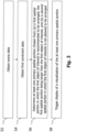
- Fig. 2 illustrates a method in accordance with the present disclosure.
- the method may be performed by the processor 202 of the processing system 200.
- the computer program stored in the memory 204 may, when executed by the processor 202, configure the processor 202 to perform the method as described herein.
- the method is not limited thereto and may be performed by another processor.
- the method comprises a step S2 of obtaining scene data indicative of a spatial pose of at least one item arranged within the operating room.
- the scene data may be based on data acquired by the sensor 304.
- the scene data may be based on data obtained from the tracking system 400.
- the scene data may comprise spatial information on a portion of the operating room comprising the at least one item.
- the spatial information may be associated with one or both coordinate systems 306, 408.
- the at least one item may comprise or consist of a patient's body or a portion thereof.
- the method comprises a step S4 of obtaining first constraint data indicative of one or more requirements on a spatial relationship between a first object of interest and the at least one item arranged within the operating room.
- the first constraint data may be specific for the first object of interest.
- the first constraint data may be specific for a type of surgery or for a surgical procedure selected by the user.
- the one or more requirements may comprise at least one of a minimum distance, a maximum distance, a minimum relative angle and a maximum relative angle between the first object of interest and the at least one item.
- the one or more requirements may comprise at least one of a minimum distance, a maximum distance, a minimum relative angle and a maximum relative angle between (i) the first object of interest and (ii) a certain part of the at least one item, a certain point on the at least one item or a certain path with respect to the at least one item.
- the certain part, point or path may be defined by planning data (e.g., in the coordinate system 602).
- the certain part may be a tumor within the patient's body.
- the certain point may be a planned entry point on the patient's body (e.g., the point 4).
- the certain path may be a planned trajectory such as a planned insertion trajectory (e.g., of a biopsy needle or a surgical drill).
- the method may comprise obtaining the planning data to determine the one or more requirements on the spatial relationship between the first object of interest and the patient's body.
- the first object of interest may be the electromagnetic field generator 408.
- the method comprises a step S6 of determining, based on the scene data and the first constraint data, at least one primary spatial portion chosen from (a) a first spatial portion in which the first object of interest is recommended to be arranged, the first spatial portion being larger than the first object of interest, and (b) a second spatial portion in which the first object of interest is not allowed to be arranged.
- Determining the first spatial portion may comprise: obtaining object data indicative of a surface of the first object of interest; determining, based on the scene data and the first constraint data, a plurality of poses in which the first object of interest is recommended to be arranged; and determining a virtual surface for each of the plurality of poses based on the object data, wherein the first spatial portion encloses all virtual surfaces.
- the plurality of recommended poses may each fulfil at least one of the requirements indicated by the first constraint data.
- determining the second spatial portion may comprise: obtaining object data indicative of a surface of the first object of interest (e.g., if not already obtained for determining the first spatial portion); determining, based on the scene data and the first constraint data, a plurality of poses in which the first object of interest is not allowed to be arranged; and determining a virtual surface for each of the plurality of poses based on the object data, wherein the second spatial portion encloses all virtual surfaces.
- the method may comprise, once one of the first portion and the second portion have been determined, using an inverse of the determined portion (e.g., all spatial portions that are not part of the determined portion) as the other of the first portion and the second portion.
- the first spatial portion does not necessarily need to be larger than the first object of interest.
- the first spatial portion may comprise only one virtual surface (e.g., if there is only one pose in which the first object of interest is recommended to be arranged).
- the method comprises a step S8 of triggering display of a visualization of the at least one primary spatial portion to guide a user on where to arrange the first object of interest in the operating room.
- the visualization of the first spatial portion informs the user in which area or volume of the operating room the first object of interest should be arranged.
- the visualization of the second spatial portion informs the user in which area or volume of the operating room the first object of interest is not to be arranged. This supports the user in arranging the first object of interest in a recommended position and orientation without having to bear in mind corresponding setup information (e.g., provided in a user manual of the first object of interest).
- the spatial portions described herein may be two-dimensional or three-dimensional spatial portions. Accordingly, the visualization of the respective spatial portion(s) described herein may be a two-dimensional or a three-dimensional visualization.
- the visualization(s) described herein may be displayed on the display 302.
- the visualization(s) described herein may be displayed relative to (e.g., overlaid onto) an acquired image or a view of (e.g., at least a part of) the operating room.
- the visualization(s) described herein may be displayed relative to (e.g., overlaid onto) the patient image data 600.
- the method may comprise obtaining the patient image data 600.
- the method may also comprise obtaining a transformation between the coordinate system 602 and the coordinate system in which the spatial pose of the at least one item is indicated by the scene data (e.g., the coordinate system 306 or 408).
- the method may comprise transforming the at least one primary spatial portion into one or more of the coordinate systems 306, 408, 602 (e.g., using one or more transformations as described above).
- Fig. 3 schematically illustrates an exemplary display content in accordance with the present disclosure.
- the display content includes the patient's head 2 and the planned entry point 4.
- the item arranged in the operating room in this case corresponds to the patient's head 2.
- the display content further includes the visualization of the first spatial portion 6 and the visualization of the second spatial portion 8.
- the first spatial portion 6 extends around the patient's head 2 in a cranial and lateral area or volume.
- the first spatial portion in this example denotes a volume in which the field generator 404 is to be arranged relative to the patient's head 2.
- the first object of interest in this example is the field generator 404.
- the second spatial portion 8 extends next to the patient's head 2 in a caudal volume.
- the second spatial portion 8 informs the user about a volume in which the field generator 404 is not allowed to be arranged. It can be seen that the portion 8 does not take up the whole volume except the portion 6. In other words, there are volumes that are not visualized or visually highlighted. This may be because the field generator may be allowed to be arranged in other poses external to the portion 6, although it is not recommended. When presented with the view shown in Fig. 3 , the user is informed in an easily understandable manner where and how to arrange the field generator 404.
- the method may further comprise triggering (e.g., in response to determining the first spatial portion) display of an instruction to arrange the first object of interest in the first spatial portion.
- the instruction may include an identification of the first object of interest (e.g., a name, an identification number or a picture representation thereof) to inform the user which object to place in the primary spatial portion.
- the instruction(s) described herein may be displayed on the same display as the visualization(s), for example on the display unit 302.
- the method may comprise obtaining first alignment data indicative of a spatial relationship between the first object of interest arranged in the operating room and the at least one item.
- the instruction may be determined based on the first alignment data.
- the instruction may indicate at least one of the one or more requirements of the first constraint data and whether or to what extent the at least one requirement is fulfilled by a current pose of the at least one first object of interest.
- the method may comprise obtaining the first alignment data and determining the instruction based thereon (e.g., the instruction indicating at least one of the one or more requirements of the first constraint data and whether or to what extent the at least one requirement is fulfilled by a current pose of the first object of interest).
- the method may then further comprise triggering display of this instruction.
- the first spatial portion may comprise at least two first sub-portions.
- Each first sub-portion comprises at least one recommended position of the first object of interest, and each of the first sub-portions is associated with a different degree of recommendation (e.g., a different degree of prioritization).
- the visualization of the first spatial portion may then comprise a distinguishable visualization of each first sub-portion.
- the first sub-portions may be visualized differently using different colors or opacities.
- the degree of recommendation of a sub-portion may be higher the more of the requirements (e.g., as indicated by the first constraint data) are fulfilled when arranging the first object in the respective sub-portion.
- the requirements indicated by the first constraint data may be associated with respective priority values, wherein the degree of recommendation of a sub-portion is higher the higher the priority values of the fulfilled requirements (e.g., when arranging the first object in the respective sub-portion) are.
- the first spatial portion 6 comprises sub-portions 10, 12.
- the sub-portion 12 comprises poses of the first object of interest that fulfill more of the requirements than all poses of the first object of interest comprised in the sub-portion 10.
- the sub-portion 12 is prioritized (e.g., because placing the field generator 404 in the first sub-portion 12 enables a most accurate tracking of a biopsy needle inserted into the point 4).
- the method comprises obtaining, for each of at least one second object of interest, second constraint data indicative of one or more requirements on a spatial relationship between the second object of interest and the first object of interest.
- the second constraint data may be specific for at least one of the first object of interest and the at least on second object of interest.
- the second constraint data may be specific for a type of surgery or for a surgical procedure selected by the user.
- the one or more requirements may comprise at least one of a minimum distance, a maximum distance, a minimum relative angle and a maximum relative angle between the at least one second object of interest and the first object of interest.
- the at least one second object of interest may comprise a patient tracker (e.g., the electromagnetic sensor 406 or an optical tracking marker attached to the patient's body).
- the method further comprises determining, for each of the at least one second object of interest, based on the determined primary spatial portion and the second constraint data, at least one secondary spatial portion chosen from (a) a third spatial portion in which the second object of interest is recommended to be arranged, and (b) a fourth spatial portion in which the second object of interest is not allowed to be arranged.
- Determining the third spatial portion for a second object of interest may comprise: obtaining object data indicative of a surface of the second object of interest; determining, based on the determined primary spatial portion and the second constraint data, a plurality of poses in which the second object of interest is recommended to be arranged; and determining a virtual surface for each of the plurality of poses based on the object data, wherein the third spatial portion encloses all virtual surfaces.
- the plurality of recommended poses may each fulfil at least one of the requirements indicated by the second constraint data.
- determining the fourth spatial portion for a second object of interest may comprise: obtaining object data indicative of a surface of the second object of interest (e.g., if not already obtained for determining the third spatial portion); determining, based on the determined primary spatial portion and the second constraint data, a plurality of poses in which the second object of interest is not allowed to be arranged; and determining a virtual surface for each of the plurality of poses based on the object data, wherein the fourth spatial portion encloses all virtual surfaces.
- the method may comprise, once one of the third portion and the fourth portion have been determined, using an inverse of the determined portion (e.g., all spatial portions that are not part of the determined portion) as the other of the third portion and the fourth portion.
- the third spatial portion may be larger than the second object of interest. It is noted that in one variant, the third spatial portion does not necessarily need to be larger than the second object of interest.
- the third spatial portion may comprise only one virtual surface (e.g., if there is only one pose in which the second object of interest is recommended to be arranged).
- the second constraint data is further indicative of one or more requirements on a spatial relationship between the second object of interest and the at least one item arranged in the operating room.
- the secondary spatial portion may then be determined further based on the scene data.
- the secondary spatial portion in this variant not only depends indirectly on the pose of the item by depending on the determined primary spatial portion (e.g., the first spatial portion), but depends directly on the pose of the at least one item.
- the method comprises triggering, for each of the at least one second object of interest, display of a visualization of the at least one secondary spatial portion to guide a user on where to arrange the at least one second object of interest in the operating room.
- the visualization of the third spatial portion is denoted by reference sign 14 and the visualization of the fourth spatial portion is denoted with reference sign 16.
- the second object of interest is the sensor 406 that is to be attached onto the head 2 of the patient before beginning a surgical procedure (e.g., before inserting a biopsy needle into the point 4).
- the third spatial portion 14 and the fourth spatial portion 16 each differ from the first and the second spatial portions 6, 8. This is only an advantageous example, and it may well be possible for the third and the fourth spatial portion 14, 16 to overlap one or both of the first and the second spatial portion 6, 8.
- the third spatial portion may therefore comprise at least two third sub-portions, each third sub-portion comprising at least one recommended position of the second object of interest, wherein each of the third sub-portions is associated with a different degree of recommendation.
- the visualization of the third spatial portion may comprise a distinguishable visualization of each third sub-portion.
- the degree of recommendation of a sub-portion may be higher the more of the requirements (e.g., as indicated by the second constraint data) are fulfilled when arranging the first object in the respective sub-portion.
- the requirements indicated by the second constraint data may be associated with respective priority values, wherein the degree of recommendation of a sub-portion is higher the higher the priority values of the fulfilled requirements (e.g., when arranging the first object in the respective sub-portion) are.
- the third spatial portion 14 comprises sub-portions 18, 20 visualized in a different manner.
- the sub-portion 20 has a higher degree of priority than the sub-portion 18, because when the sensor 406 is arranged in the sub-portion 20, more of the requirements of the second constraint data, or higher prioritized requirements of the second constraint data, are fulfilled compared with when the sensor 406 is arranged in the sub-portion 18.
- the visualizations may be updated accordingly upon placement of the first object of interest or the second object of interest.
- the method may comprise obtaining first alignment data indicative of a spatial relationship between the first object of interest arranged in the operating room and the at least one item.
- the first alignment data may be obtained from at least one of the ARD 300 and the tracking system 400.
- the first alignment data may indicate a relative spatial relationship (e.g., a relative pose) between the first object of interest and the at least one item as captured by the sensor 304 or the localizer 402.
- the ARD 300 may capture a depth image of the patient's head 2 and of the field generator 404.
- the first alignment data may then be determined based on the depth image by detecting both the head 2 and the field generator 303 in the depth image and determining the spatial relationship therebetween (e.g., in the coordinate system 306).
- relative poses between the field generator 404 and the head 2 may be captured by an optical tracking system (e.g., by localizing an optical tracking marker attached to the head 2 and an optical tracking marker attached to the field generator 404).
- the method may comprise determining, for each of the at least one second object of interest, an updated instance of the at least one secondary spatial portion based on the second constraint data and the first alignment data.
- the updated instance of the at least one secondary spatial portion may be determined in a similar way as described above for the at least on secondary spatial portion, but use the pose of the at least one item instead of the primary spatial portion during the determination. In result, this will in most cases lead to a smaller updated secondary spatial portion (e.g., taking only a current pose of the item as a reference for the requirements of the second constraint data) compared to the secondary spatial portion (e.g., taking all poses within the primary spatial portion as a reference for the requirements of the second constraint data).
- the placement of the first object of interest influences or affects the third (e.g., and the fourth) spatial portion.
- the method may comprise updating, for each of the at least one second object of interest, the display of the visualization of the at least one secondary spatial portion based on (e.g., by triggering display of) the updated instance of the at least one secondary spatial portion.
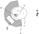
- Fig. 4 schematically illustrates the display content of Fig. 3 , but after the field generator 404 has been placed in the first spatial portion 6.
- the field generator 404 was placed in an optimal manner, namely, in the most prioritized sub-portion 12.
- the visualization of the primary spatial portion for example the visualization of the first and/or the second spatial portion 10, 12, may still be visualized despite placement of the first object of interest in the first spatial portion 10.
- the first spatial portion 10 is still visualized, whereas the second spatial portion 8 is no longer shown.
- the third spatial portion 14 is updated accordingly.
- the updated instance of the third spatial portion 14 is only determined using the actual pose of the field generator 404. For that reason, the updated third spatial portion 14 shown in Fig. 4 is smaller compared with the third spatial portion 14 shown in Fig. 3 .
- the updated instance of the at least one secondary spatial portion may be determined in response to or as a reaction to the first alignment data indicating that the first object of interest is arranged within the first spatial portion. Again, this responsive determination may avoid unnecessary re-computations.
- An instruction to arrange one or more of the at least one second object of interest in the third spatial portion may be triggered to be displayed responsive to the first alignment data indicating that the first object of interest is arranged within the first spatial portion.
- the instruction may alternatively be triggered to be displayed upon determining the third spatial portion.
- the instruction may comprise an identification of the at least one second object of interest.
- sequence data may be obtained.
- the sequence data may be indicative of a recommended sequence of placement of the plurality of second objects of interest.
- the recommended sequence may be associated with a type of surgery or a surgical procedure selected by a user.
- the recommended sequence may be patient-specific.
- the recommended sequence may be specific for at least one component chosen from the item and the first object of interest.
- the instruction may be determined based on the sequence data and comprise an identification of a second object of interest recommended to be placed next.
- the method may comprise obtaining second alignment data indicative of a spatial relationship between the at least one primary spatial portion and one or more of the at least one second object of interest arranged in the operating room.
- the instruction may be determined based on the second alignment data.
- the instruction may indicate at least one of the one or more requirements of the second constraint data and whether or to what extent the at least one requirement is fulfilled by a current pose of the at least one second object of interest.
- the method may comprise obtaining the second alignment data and determining the instruction based thereon (e.g., the instruction indicating at least one of the one or more requirements of the second constraint data and whether or to what extent the at least one requirement is fulfilled by a current pose of the at least one second object of interest).
- the method may then further comprise triggering display of this instruction.
- placement of the first object of interest may influence the secondary spatial portion.
- placement of the second object of interest may affect the primary spatial portion.
- the method may comprise determining an updated instance of the at least one primary spatial portion based on the second constraint data and the second alignment data.
- the second alignment data may be obtained from at least one of the ARD 300 and the tracking system 400.
- the second alignment data may indicate a relative spatial relationship (e.g., a relative pose) between the second object of interest and at least one of the first object and the at least one item as captured by the sensor 304 or the localizer 402.
- the ARD 300 may capture a depth image of the field generator 404 and of the sensor 406.
- the first alignment data may then be determined based on the depth image by detecting both the field generator 404 and the sensor 406in the depth image and determining the spatial relationship therebetween (e.g., in the coordinate system 306).
- a relative pose between the field generator 404 and the sensor 406 may be captured by the tracking system 400 (e.g., by the localizer 402).
- the method may comprise updating the display of the visualization of the at least one primary spatial portion based on (e.g., by triggering display of) the updated instance of the at least one primary spatial portion.
- the displayed primary spatial portion may react to the placement of the at least one second object of interest.
- the secondary primary spatial portion may be updated (e.g., again) as well. As noted above, it may not be required to display the visualizations of the primary or the secondary spatial portion after placement of both the first and the second object of interest.
- displaying these visualizations may allow a user to move and re-position the first and the second object of interest within the respective first and third spatial portions to optimize their placement (e.g., by arranging each of the objects of interest in a higher-ranked sub-portion).
- Fig. 5 illustrates an updated display content that corresponds to that shown in Fig. 4 , but after a second object of interest has been placed.
- the second object of interest corresponds to the sensor 406.
- the first spatial portion 6 has decreased in size (e.g., volume). This is because the first spatial portion 6 in Fig. 5 has been updated by comparing the requirements indicated by the second constraint data with the captured pose of the patient tracker 406.
- the size of the third spatial portion 14 has decreased, because the third spatial portion 14 is updated based on the updated instance of the primary spatial portion, for example based on the updated, smaller first spatial portion 6.
- An instruction indicating at least one of the one or more requirements of the second constraint data and whether or to what extent the at least one requirement is fulfilled by a current pose of the at least one second object of interest may be visualized.
- the updated instance of the at least one primary spatial portion may be determined responsive to the second alignment data indicating that the one or more of the at least one second object of interest are arranged within the third spatial portion determined for the one or more of the at least one second object of interest.
- the first object of interest may correspond to the patient tracker, for example the sensor 406.
- the second object of interest may then correspond to the field generator 404.
- the initial display content before placement of the first or second object of interest may correspond to that of Fig. 3 , whilst the reference signs of the primary spatial portion 6, 8, 10, 12 on the one hand and the secondary spatial portion 14, 16, 18, 20 on the other hand would need to be interchanged.
- the third spatial region 14 may be updated.
- the resultant display content is exemplarily illustrated in Fig. 6 .
- the resulting display content may correspond to that shown in Fig. 6 whilst the reference signs 14, 6 would need to be interchanged.
- the present disclosure is not limited to a single second object of interest.
- a user may be guided on where to place multiple second objects of interest.
- For each of the second objects of interest a separate instance of the secondary spatial portion and, optionally, a separate instruction may be determined and visualized.
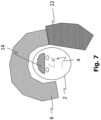
- the display content may comprise a visualization of a plurality of third spatial portions 14, 22.
- the first spatial region 6 is associated with the field generator 404 (e.g., the field generator 202 is to be placed within the first spatial region 6)
- the third spatial region 14 is associated with the sensor 406 and another third spatial region 22 is associated with another second object of interest (e.g., the surgical instrument 500 configured as a biopsy needle guide).
- the individual (e.g., instances of) secondary spatial portions may be affected by placement of one or more of the second objects of interest.
- One may say that the secondary spatial portions affect one another.
- the method may further comprise obtaining, for one of the at least one second object of interest (e.g., the sensor 406), third constraint data indicative of one or more requirements on a spatial relationship between the one of the at least one second object of interest (e.g., the sensor 406) and another one or more of the at least one second object of interest (e.g., the instrument 500), wherein the at least one secondary spatial portion of the one of the at least one second object of interest (e.g., the third spatial portion 14 associated with the sensor 406) is determined further based on the third constraint data.
- the degree of recommendation of the third spatial portion of one of the at least one second object of interest may then alternatively or additionally depend on the third constraint data.
- the third constraint data may be specific for the one of the one of the at least one second object of interest.
- the third constraint data may be specific for the another one or more of the at least one second object of interest.
- the third constraint data may be specific for a type of surgery or for a surgical procedure selected by the user.
- the one or more requirements may comprise at least one of a minimum distance, a maximum distance, a minimum relative angle and a maximum relative angle between the one of the at least one second object of interest and the another one or more of the at least one second object of interest.
- the method may further comprise obtaining third alignment data indicative of a spatial relationship between (i) the at least one secondary spatial portion of the one of the at least one second object of interest (e.g., the sensor 406) and (ii) the another one or more of the at least one second object of interest (e.g., the instrument 500) arranged in the operating room.
- the third alignment data may describe a spatial relationship between the third spatial portion (e.g., the third spatial portion 14) and one of the second objects of interest not associated with the third spatial portion (e.g., the instrument 500 associated with the third spatial portion 22).
- the third alignment data may be obtained from the ARD 300 or the tracking system 400.
- the third alignment data may be obtained similarly as described above for the first and the second alignment data.
- an updated instance of the at least one secondary spatial portion (e.g., the third spatial portion 14) of the one of the at least one second object of interest (e.g., the sensor 406) may be determined.
- the display of the visualization of the at least one secondary spatial portion (e.g., the third spatial portion 14) of the one of the at least one second object of interest (e.g., the sensor 406) may be updated (e.g., responsive to the third alignment data indicating that the another one or more of the at least one second object of interest have been placed within the respective third spatial portions).
- the at least one item may comprise a part (e.g., the head 2) of a patient's body or may correspond to the patient's body. Alternatively or additionally, the at least one item may correspond to a medical device.
- the first object of interest may be a first medical device and the at least one second object of interest may comprise or consist of at least one second medical device.
- the respective medical device may be one of a field generator (e.g., the field generator 404), an electromagnetic sensor (e.g., the sensor 406), a surgical instrument (e.g., the instrument 500), a biopsy needle, a stereo camera of an optical tracking system, an optical tracking marker (e.g., to be) attached to the patient, another tracker or an implant (e.g., a metal implant such as a surgical screw or a bone plate).
- a field generator e.g., the field generator 404
- an electromagnetic sensor e.g., the sensor 406
- a surgical instrument e.g., the instrument 500
- a biopsy needle e.g., a biopsy needle
- a stereo camera of an optical tracking system e.g., an optical tracking marker (e.g., to be) attached to the patient
- an optical tracking marker e.g., to be attached to the patient
- another tracker or an implant e.g., a metal implant such as a surgical screw or
- the present disclosure provides for a solution in which the first object of interest shall be placed before the at least one second object of interest.
- a first of the at least one second object of interest shall be placed before a second of the at least one object of interest.
- This sequence may be communicated to the user by displaying the aforementioned instruction(s). The sequence may be indicated by the sequence data as described above. A plurality of consecutive instructions may be displayed, each informing the user which object to place next. A subsequent one of the instructions may be displayed in response to the alignment data indicating that a current object of interest has been correctly placed.
- the first object of interest is the field generator 404 and the (e.g., first or second of the) at least one second object of interest is the patient tracker (e.g., the sensor 406 or an optical tracking marker attached to the patient's body).
- the patient tracker e.g., the sensor 406 or an optical tracking marker attached to the patient's body.
- the first object of interest is the patient tracker (e.g., the sensor 406)
- the first of the at least one second object of interest is the surgical instrument 500 configured as a biopsy guide
- the second of the at least one second object of interest is the field generator 404 or the stereo camera of the tracking system.
- the first object of interest is the surgical instrument 500 configured as a biopsy guide
- the first of the at least one second object of interest is the patient tracker (e.g., the sensor 406) and the second of the at least one second object of interest is the field generator 404 or the stereo camera of the tracking system.
- the first object of interest is the field generator 404 or the stereo camera of the tracking system
- the first of the at least one second object of interest is the patient tracker (e.g., the sensor 406) and the second of the at least one second object is the surgical instrument 500 configured as a biopsy guide.
- the at least one item comprises an operating table and the first object of interest corresponds to the patient's body (e.g., the head 2).
- the first of the at least one second object of interest may be the field generator 404 and the second of the at least one second object of interest may be the patient tracker.
- the scene data may be obtained from the ARD 300, for example from the sensor 304.
- the method may comprise obtaining sensor data captured by the at least one sensor 304. Based on the sensor data, at least one component chosen from the first object of interest and the at least one item may be detected (e.g., using one or more object recognition algorithms).
- a pose of the at least one component relative to the sensor 304 for example a pose in the coordinate system 306, may be determined after having detected the at least one component.
- a spatial relationship between the detected at least one component and the ARD 300 (e.g., configured as a HMD) may be determined.
- the method may comprise determining the visualization based on the spatial relationship between the detected at least one component and the ARD 300.
- the sensor 304 may be used to detect a current pose of the patient's head 2 relative to the ARD 300 (e.g., a current pose in the coordinate system 306). This may allow for overlaying the primary and the secondary spatial portion in an augmented manner in a view comprising the head 2. No tracking data may be required from a tracking system in this case, which allows for guidance on where and how to arrange components of the tracking system (e.g., where to arrange the field generator 404 and the sensor 406), even before activating the tracking system.
- the localizer 402 e.g., or the processor 202, using data obtained from the tracking system 400
- This relative pose may be determined with a high accuracy and used to update at least one of the primary spatial portion and the secondary spatial portion.
- a tracking device e.g., the field generator 404 or a stereo-camera of an optical tracking system
- the patient's body e.g., the head 2
- the surgical site is situated within the optimal tracking volume of the tracking device.
- constraints that either originate from the type of surgery (e.g., otolaryngology, cranial surgery, etc.) or a specific surgical procedure (e.g., insertion of a biopsy needle or an instrument along an entry path) that need to be fulfilled for an optimal surgery performance and outcome.
- the present disclosure may be considered as providing for a technique on communicating these constraints to the user to achieve an appropriate user action.
- Typical objects of interest to be placed are the field generator 404 or stereo-camera, the patient tracker (e.g., the sensor 406) or a biopsy needle.
- typical constraints for the placement of the objects are the pose of the patient's body, the pose and type of an operating table, the pose and type of a system cart and monitor, the pose and type of a Mayfield clamp or other components that influence tracking quality.
- a tracking system (e.g., the tracking system 400) may be at least measuring the pose of a patient tracker (e.g., the sensor 406) rigidly attached to the patient.
- a patient tracker e.g., the sensor 406
- navigation system components e.g., the field generator 404 and the sensor 406
- an exact position of the patient in relation to the patient tracker might be unknown.
- a registration between the patient image data 600 and the tracking system 400, resulting in a transformation between the coordinate system 602, 408 may not yet be known. Nevertheless, a guidance for optimal placement of the tracking system in relation to the patient may be provided by the technique disclosed herein.
- the one or more requirements indicated by the constraint data disclosed herein may be classified in two main categories: procedure information and operating room setup information.
- the procedure information requirements may be given by the type of surgery and the surgical procedure, and, optionally, by a procedure planning (e.g., the planning data).
- the procedure information requirements may be used to derive an optimal pose or setup of the tracking system components (e.g., a pose of the field generator 404) and other tracking related components.
- the procedure information requirements are indicated in Fig. 8 and may depend on or be determined based on one or more of the (e.g., pose of the) entry point 4, a critical structure (e.g., a vessel), draped areas, an allowed tracking system area in the operating room, a target are or point, existing screws, an allowed patient tracker area, etc.
- the procedure information requirements may be dependent on or determined based on at least one of (i) the patient image data 600, (ii) the planning data, (iii) the type of surgery selected by the user or indicated by the planning data (e.g., functional endoscopic sinus surgery (FESS), cochlea surgery, biopsy, etc.), and (iv) external information about a current operating room setup (e.g., from a spatial mapping or video images, for example acquired by the sensor 304).
- FESS functional endoscopic sinus surgery
- cochlea surgery e.g., cochlea surgery, biopsy, etc.
- external information about a current operating room setup e.g., from a spatial mapping or video images, for example acquired by the sensor 304.
- the operating room setup information requirements may depend on tracking data, object and item properties and physical models of the patient's body, of objects and items, etc.
- the operating room setup information requirements are also indicated in Fig. 8 and may depend on one or more of a tracking system measurement area, tracking characteristics of tracking system components, a working area of components (e.g., a surgical instrument or at least one of the first object of interest, the at least one second object of interest and the item), a shape of the components, physically possible configurations, a disturbing component negatively affecting the tracking accuracy, etc.
- the operating room setup information requirements may be dependent on or determined based on at least one of (i) spatial mapping data, (ii) spatial understanding data, (iii) a webcam or depth-image, for example acquired by the sensor 304, (iv) marker-based and/or marker-less tracking of components (e.g., the object(s) or the item), (v) model information of components (e.g., as STL mesh data), (vi) geometric properties of the components, and (vii) tracking data from tracking system (e.g., the tracking system 400).
- components e.g., the object(s) or the item
- model information of components e.g., as STL mesh data
- geometric properties of the components e.g., the tracking system 400.
- Fig. 8 also indicates that "allow areas” may be combined with a “tracking area”.
- the requirements define a viewing area or an effective tracking area or volume of a tracker of the tracking system (e.g., a stereo-camera or an electromagnetic field generator).
- the requirements may also indicate a spatial requirement with respect to an entry point and a target size and pose.
- the position areas to be proposed (“Proposed Position Areas") may correspond to the primary, first, second, secondary, third and/or fourth spatial portions described above. Placement of the objects may influence the proposed areas ("Refine with set positions of other components"). Tracking data obtained from the tracking system may be used to determine an accurate spatial pose of one or more objects and to update the spatial portions accordingly. Objects should be placed such that they do not disturb the tracking quality ("Optimize tracking quality").
- the method described herein may optimize a spatial relation between the navigation system 400 and involved components and recommend positioning areas weighted by their quality.
- the recommended positioning areas e.g., the first spatial portion and the third spatial portion(s)
- the components e.g., the first object of interest and the at least one second object of interest
- the recommended positioning areas may be dynamically refined.
- the components to be arranged may comprise but are not limited to an operating room table, a navigation system, a cart, a mounting arm, a robot, an imaging device, a surgical tool or instrument, staff and working areas of staff.
- Fig. 9 may be regarded as an exemplary and more detailed illustration of the method described above with reference to Fig. 2 .
- the "Visualization of Proposed Position Area For Field Generator” in Fig. 9 may correspond to the first spatial portion described herein.
- the "Visualization of Proposed Position Area For Patient Tracker” may correspond to the third spatial portion described herein.
- the "User Interaction” may correspond to a placement of the first object of interest (e.g., the field generator 404) or the second object of interest (e.g., the sensor 406) or a movement thereof. That is, the visualization(s) may not only be updated upon placement of an object of interest, but also in response to a movement thereof.
- the step "Optimizing Positions based on Constraints” shown in Fig. 9 may correspond to the similarly named step of Fig. 8 .
- the "OR-Setup Information" of Fig. 9 may include the operating room setup information requirements (e.g., as described above with reference to Fig. 8 ).
- the "Procedure Information” of Fig. 9 may include the procedure information requirements (e.g., as described above with reference to Fig. 8 ).
- the combination of the "OR-Setup Information” and the "Procedure Information” may be considered to represent the first constraint data, the second constraint data and the third constraint data.
- the resulting operating room setup proposals may represent a three-dimensional arrangement of the tracking system components relative to the patient (e.g. the patient's head in ENT surgery) or a setup component. This arrangement may either be displayed on a monitor of a navigation system (e.g., comprising the tracking system 400) or on the ARD 300 (e.g. Microsoft HoloLens ® ).
- a navigation system e.g., comprising the tracking system 400
- ARD 300 e.g. Microsoft HoloLens ®
- the ARD 300 may visualize guidance information for an optimal operating room setup directly in the real world. This guidance may be based on a pre-registration of the patient, the field generator 404 and the patient tracker 406 with respect to the coordinate space 306 of the head-mounted display. This pre-registration may make use of trained models for face and object detection in a webcam image of the sensor 304 and a spatial mapping of the head-mounted display 300.
- the proposed method does not necessarily utilize tracking data from a surgical navigation system.
- guidance may be provided independent to a current state of the surgical navigation system and can help to setup the navigation system itself (e.g., the tracking system 400).
- the proposed method may allow a holistic approach for the component placement.
- the guidance visualization may be visualized on a head-mounted display. If the patient is tracked by the head-mounted display, the visualizations may be shown directly at their actual positions. In this case, the user may no longer required to mentally transfer information from abstract two-dimensional or three-dimensional visualizations.
- the operating room setup information requirements may be indicated by at least one of the first constraint data, the second constraint data and the third constraint data.
- the procedure information requirements may be indicated by at least one of the first constraint data, the second constraint data and the third constraint data.
Landscapes
- Health & Medical Sciences (AREA)
- Engineering & Computer Science (AREA)
- Life Sciences & Earth Sciences (AREA)
- Surgery (AREA)
- Biomedical Technology (AREA)
- Public Health (AREA)
- Medical Informatics (AREA)
- General Health & Medical Sciences (AREA)
- Veterinary Medicine (AREA)
- Heart & Thoracic Surgery (AREA)
- Molecular Biology (AREA)
- Animal Behavior & Ethology (AREA)
- Nuclear Medicine, Radiotherapy & Molecular Imaging (AREA)
- Physics & Mathematics (AREA)
- Robotics (AREA)
- Business, Economics & Management (AREA)
- General Business, Economics & Management (AREA)
- Epidemiology (AREA)
- Primary Health Care (AREA)
- General Physics & Mathematics (AREA)
- Optics & Photonics (AREA)
- Oral & Maxillofacial Surgery (AREA)
- Pathology (AREA)
- Processing Or Creating Images (AREA)
- User Interface Of Digital Computer (AREA)
Claims (20)
- Procédé mis en œuvre par ordinateur destiné à guider un utilisateur dans la disposition d'un objet d'intérêt dans une salle d'opération, le procédé comprenant :l'obtention (S2) de données de scène indiquant une position spatiale d'au moins un article (2) disposé dans la salle d'opération;l'obtention (S4) de premières données de contrainte indiquant une ou plusieurs exigences relatives à une relation spatiale entre un premier objet d'intérêt (404) et l'au moins un article (2) disposé dans la salle d'opération;la détermination (S6), sur la base des données de scène et des premières données de contrainte, d'au moins une portion spatiale primaire choisie parmi (a) une première portion spatiale (6) dans laquelle il est recommandé de disposer le premier objet d'intérêt (404), la première portion spatiale (6) étant plus grande que le premier objet d'intérêt (404), et (b) une deuxième portion spatiale (8) dans laquelle il n'est pas permis de disposer le premier objet d'intérêt (404) ;l'obtention, pour chacun d'au moins un deuxième objet d'intérêt (406), de données de deuxième contrainte indiquant une ou plusieurs exigences relatives à une relation spatiale entre le deuxième objet d'intérêt (406) et le premier objet d'intérêt (404);la détermination, pour chacun de l'au moins un deuxième objet d'intérêt (406), sur la base de la portion spatiale primaire déterminée et des deuxièmes données de contrainte, d'au moins une portion spatiale secondaire choisie parmi (a) une troisième portion spatiale (14) dans laquelle il est recommandé de disposer le deuxième objet d'intérêt (406) et (b) une quatrième portion spatiale (16) dans laquelle il n'est pas permis de disposer le deuxième objet d'intérêt (406);le déclenchement de l'affichage d'une visualisation d'au moins une portion spatiale primaire pour guider un utilisateur dans la disposition d'un premier objet d'intérêt (404) dans la salle d'opération; etle déclenchement, pour chacun de l'au moins un deuxième objet d'intérêt (406), de l'affichage d'une visualisation d'au moins un deuxième objet d'intérêt (406) afin de guider l'utilisateur dans la disposition d'un objet d'intérêt dans une salle d'opération.
- Procédé selon la revendication 1, dans lequel la première portion spatiale (6) comprend au moins deux premières sous-portions (10, 12), chaque première sous-portion (10 ; 12) comprenant au moins une position recommandée du premier objet d'intérêt (404), chacune des premières sous-portions (10 ; 12) étant associée à un degré de recommandation différent, la visualisation de la première portion spatiale (6) comprenant une visualisation distincte de chaque première sous-portion (10 ; 12).
- Procédé selon la revendication 1 ou 2, dans lequel la troisième portion spatiale (14) est plus grande que le deuxième objet d'intérêt (406).
- Procédé selon l'une quelconque des revendications 1 à 3, dans lequel la troisième portion spatiale (14) comprend au moins deux troisièmes sous-portions (18, 20), chaque troisième sous-portion (18 ; 20) comprenant au moins une position recommandée du deuxième objet d'intérêt (406), chacune des troisièmes sous-portions (18 ; 20) étant associée à un degré de recommandation différent, la visualisation de la troisième portion spatiale (14) comprenant une visualisation distincte de chaque troisième sous-portion (18 ; 20).
- Procédé selon l'une quelconque des revendications 1 à 4, comprenant en outre:l'obtention des premières données d'alignement indiquant une relation spatiale entre le premier objet d'intérêt (404) disposé dans la salle d'opération et l'au moins un article (2);la détermination, pour chacun des au moins un deuxième objet d'intérêt (406), d'une instance mise à jour de l'au moins une portion spatiale secondaire sur la base des deuxièmes données de contrainte et des premières données d'alignement; etla mise à jour, pour chacun de l'au moins un deuxième objet d'intérêt (406), l'affichage de la visualisation d'au moins une portion spatiale secondaire sur la base de l'instance mise à jour de l'au moins une portion spatiale secondaire.
- Procédé selon la revendication 5, dans lequel l'instance mise à jour de l'au moins une portion spatiale secondaire est déterminée en fonction des premières données d'alignement indiquant que le premier objet d'intérêt (404) est disposé à l'intérieur de la première portion spatiale (6).
- Procédé selon la revendication 5 ou 6, comprenant en outre:
en réponse aux premières données d'alignement indiquant que le premier objet d'intérêt (404) est disposé dans la première portion spatiale (6), le déclenchement de l'affichage d'une instruction pour disposer un ou plusieurs des au moins un deuxième objet d'intérêt (406) dans la troisième portion spatiale (14) déterminée pour la ou les parmi l'au moins un deuxième objet d'intérêt (406). - Procédé selon l'une quelconque des revendications 1 à 7, comprenant en outre:l'obtention de secondes données d'alignement indiquant une relation spatiale entre l'au moins une portion spatiale primaire et un ou plusieurs de l'au moins un second objet d'intérêt (406) disposé dans la salle d'opération;la détermination d'une instance mise à jour de l'au moins une portion spatiale primaire sur la base des deuxièmes données de contrainte et des deuxièmes données d'alignement; etla mise à jour de l'affichage de la visualisation de l'au moins une portion spatiale primaire sur la base de l'instance mise à jour de l'au moins une portion spatiale primaire.
- Procédé selon la revendication 8, dans lequel l'instance mise à jour de l'au moins une portion spatiale primaire est déterminée en fonction des deuxièmes données d'alignement indiquant que le ou les de l'au moins un deuxième objet d'intérêt (406) sont disposés à l'intérieur de la troisième portion spatiale (14) déterminée pour le ou les objets parmi l'au moins un deuxième objet d'intérêt (406).
- Procédé selon l'une quelconque des revendications 1 à 9, comprenant en outre:l'obtention, pour l'un de l'au moins un deuxième objet d'intérêt (406), des troisièmes données de contrainte indiquant une ou plusieurs exigences relatives à une relation spatiale entre l'un de l'au moins un deuxième objet d'intérêt (406) et un ou plusieurs autres de l'au moins un deuxième objet d'intérêt,dans lequel l'au moins une portion spatiale secondaire de l'un de l'au moins un deuxième objet d'intérêt (406) est déterminée en outre sur la base des troisièmes données de contrainte.
- Procédé selon la revendication 10, comprenant en outre:l'obtention de troisièmes données d'alignement indiquant une relation spatiale entre (i) l'au moins une portion spatiale secondaire de l'un de l'au moins un deuxième objet d'intérêt (406) et (ii) un ou plusieurs autres de l'au moins un deuxième objet d'intérêt disposés dans la salle d'opération;la détermination, sur la base des troisièmes données de contrainte et des troisièmes données d'alignement, d'une instance mise à jour de l'au moins une portion spatiale secondaire de l'un d l'au moins deuxième objet d'intérêt (406); etla mise à jour, sur la base de l'instance mise à jour de l'au moins une portion spatiale secondaire, de l'affichage de la visualisation de l'au moins une portion spatiale secondaire de l'un de l'au moins un deuxième objet d'intérêt (406).
- Procédé selon l'une quelconque des revendications 1 à 11, comprenant en outre:
le déclenchement d'affichage d'une instruction pour disposer le premier objet d'intérêt (404) dans la première portion spatiale (6). - Procédé selon l'une quelconque des revendications 1 à 12, dans lequel au moins l'une des exigences satisfait à au moins l'une des exigences suivantes:- elle est spécifique au patient;- elle est associée à un type de chirurgie sélectionnée par l'utilisateur;- elle est associée à une intervention chirurgicale sélectionnée par l'utilisateur.
- Procédé selon l'une quelconque des revendications 1 à 13, dans lequel l'au moins un article (2) comprend une partie du corps d'un patient et le premier objet d'intérêt est un dispositif médical (404 ; 406 ; 500).
- Procédé selon l'une quelconque des revendications 1 à 14, dans lequel la visualisation est déclenchée pour être affichée en superposition sur une vue d'au moins une partie de la salle d'opération.
- Procédé selon l'une quelconque des revendications 1 à 15, dans lequel la visualisation est déclenchée pour être affichée sur l'écran d'un visiocasque, HMD, (300).
- Procédé selon la revendication 16, dans lequel le HMD (300) comprend au moins un capteur (304) choisi parmi un capteur optique et un capteur de profondeur, le procédé comprenant en outre:l'obtention des données de capteur capturées par l'au moins un capteur (304);la détection, sur la base des données du capteur, au moins d'un composant choisi parmi le premier objet d'intérêt (404) et au moins un article (2);la détermination d'une relation spatiale entre l'au moins un composant détecté (2 ; 404) et le HMD (300); etla détermination de la visualisation sur la base de la relation spatiale entre l'au moins un composant détecté (2; 404) et le HMD (300).
- Système de traitement (200) comprenant au moins un processeur (202), l'au moins un processeur (202) étant configuré pour mettre en œuvre le procédé selon l'une quelconque des revendications 1 à 17.
- Programme informatique comprenant des instructions qui, lorsque le programme est exécuté par au moins un processeur (202), amènent l'au moins un processeur (202) à mettre en œuvre le procédé selon l'une quelconque des revendications 1 à 17.
- Système chirurgical (100) comprenant:le système de traitement (200) selon la revendication 18; etun visiocasque, HMD, (300), le HMD (300) comprenant au moins un capteur (304) choisi parmi un capteur optique et un capteur de profondeur, dans lequel l'au moins un capteur (304) est conçu pour capturer des données de capteur permettant la détection d'au moins un composant choisi parmi le premier objet d'intérêt (404) et l'au moins un article (2).
Priority Applications (3)
| Application Number | Priority Date | Filing Date | Title |
|---|---|---|---|
| EP21204300.4A EP4169468B1 (fr) | 2021-10-22 | 2021-10-22 | Technique de fourniture de guidage à un utilisateur sur l'agencement d'un objet d'intérêt dans une salle d'opération |
| US17/968,322 US12478432B2 (en) | 2021-10-22 | 2022-10-18 | Technique for providing guidance to a user on where to arrange an object of interest in an operating room |
| CN202211300126.1A CN115998430A (zh) | 2021-10-22 | 2022-10-21 | 向用户提供在手术室中何处布置感兴趣对象的指导的技术 |
Applications Claiming Priority (1)
| Application Number | Priority Date | Filing Date | Title |
|---|---|---|---|
| EP21204300.4A EP4169468B1 (fr) | 2021-10-22 | 2021-10-22 | Technique de fourniture de guidage à un utilisateur sur l'agencement d'un objet d'intérêt dans une salle d'opération |
Publications (2)
| Publication Number | Publication Date |
|---|---|
| EP4169468A1 EP4169468A1 (fr) | 2023-04-26 |
| EP4169468B1 true EP4169468B1 (fr) | 2025-01-15 |
Family
ID=78649098
Family Applications (1)
| Application Number | Title | Priority Date | Filing Date |
|---|---|---|---|
| EP21204300.4A Active EP4169468B1 (fr) | 2021-10-22 | 2021-10-22 | Technique de fourniture de guidage à un utilisateur sur l'agencement d'un objet d'intérêt dans une salle d'opération |
Country Status (3)
| Country | Link |
|---|---|
| US (1) | US12478432B2 (fr) |
| EP (1) | EP4169468B1 (fr) |
| CN (1) | CN115998430A (fr) |
Citations (2)
| Publication number | Priority date | Publication date | Assignee | Title |
|---|---|---|---|---|
| EP2996615A1 (fr) * | 2013-03-13 | 2016-03-23 | Stryker Corporation | Système d'agencement d'objets dans une salle d'opération en vue de procédures chirurgicales |
| US20210228282A1 (en) * | 2018-03-13 | 2021-07-29 | Intuitive Surgical Operations Inc. | Methods of guiding manual movement of medical systems |
Family Cites Families (13)
| Publication number | Priority date | Publication date | Assignee | Title |
|---|---|---|---|---|
| WO2015164402A1 (fr) | 2014-04-22 | 2015-10-29 | Surgerati, Llc | Système et procédé de visualisation d'image médicale peropératoire |
| US10528840B2 (en) | 2015-06-24 | 2020-01-07 | Stryker Corporation | Method and system for surgical instrumentation setup and user preferences |
| DE102015226669B4 (de) | 2015-12-23 | 2022-07-28 | Siemens Healthcare Gmbh | Verfahren und System zum Ausgeben einer Erweiterte-Realität-Information |
| WO2017144934A1 (fr) | 2016-02-26 | 2017-08-31 | Trophy | Procédé et appareil de chirurgie guidé |
| US20170280970A1 (en) * | 2016-03-31 | 2017-10-05 | Covidien Lp | Thoracic endoscope for surface scanning |
| CN108784832A (zh) | 2017-04-26 | 2018-11-13 | 中国科学院沈阳自动化研究所 | 一种脊柱微创手术增强现实导航方法 |
| US11179200B2 (en) | 2017-12-15 | 2021-11-23 | Medtronic, Inc. | Augmented reality solution to disrupt, transform and enhance cardiovascular surgical and/or procedural mapping navigation and diagnostics |
| US11114199B2 (en) * | 2018-01-25 | 2021-09-07 | Mako Surgical Corp. | Workflow systems and methods for enhancing collaboration between participants in a surgical procedure |
| JP7225259B2 (ja) * | 2018-03-28 | 2023-02-20 | オーリス ヘルス インコーポレイテッド | 器具の推定位置を示すためのシステム及び方法 |
| US11039894B2 (en) * | 2018-04-20 | 2021-06-22 | Verb Surgical Inc. | Robotic port placement guide and method of use |
| US20220110685A1 (en) * | 2019-02-05 | 2022-04-14 | Smith & Nephew, Inc. | Methods for improving robotic surgical systems and devices thereof |
| CN109758230B (zh) | 2019-02-26 | 2021-04-13 | 中国电子科技集团公司信息科学研究院 | 一种基于增强现实技术的神经外科手术导航方法和系统 |
| US11382699B2 (en) * | 2020-02-10 | 2022-07-12 | Globus Medical Inc. | Extended reality visualization of optical tool tracking volume for computer assisted navigation in surgery |
-
2021
- 2021-10-22 EP EP21204300.4A patent/EP4169468B1/fr active Active
-
2022
- 2022-10-18 US US17/968,322 patent/US12478432B2/en active Active
- 2022-10-21 CN CN202211300126.1A patent/CN115998430A/zh active Pending
Patent Citations (2)
| Publication number | Priority date | Publication date | Assignee | Title |
|---|---|---|---|---|
| EP2996615A1 (fr) * | 2013-03-13 | 2016-03-23 | Stryker Corporation | Système d'agencement d'objets dans une salle d'opération en vue de procédures chirurgicales |
| US20210228282A1 (en) * | 2018-03-13 | 2021-07-29 | Intuitive Surgical Operations Inc. | Methods of guiding manual movement of medical systems |
Also Published As
| Publication number | Publication date |
|---|---|
| US12478432B2 (en) | 2025-11-25 |
| US20230127963A1 (en) | 2023-04-27 |
| CN115998430A (zh) | 2023-04-25 |
| EP4169468A1 (fr) | 2023-04-26 |
Similar Documents
| Publication | Publication Date | Title |
|---|---|---|
| EP4272181B1 (fr) | Système de réalité augmentée, visiocasque à réalité augmentée et procédé de réalité augmentée et programme informatique | |
| US12336771B2 (en) | Augmented reality navigation systems for use with robotic surgical systems and methods of their use | |
| US11080934B2 (en) | Mixed reality system integrated with surgical navigation system | |
| CA3011314C (fr) | Methodes et systemes de fourniture d'information visiospatiale | |
| EP3395282B1 (fr) | Vue endoscopique des procédures invasives dans les passages étroits | |
| US10506991B2 (en) | Displaying position and optical axis of an endoscope in an anatomical image | |
| US7774044B2 (en) | System and method for augmented reality navigation in a medical intervention procedure | |
| US20240315778A1 (en) | Surgical assistance system and display method | |
| EP3392835B1 (fr) | Amélioration de l'enregistrement d'une image anatomique à l'aide d'un système de coordonnées de suivi de position basé sur la proximité visuelle à un tissu osseux | |
| CN115363754B (zh) | 提供用户指导以获得患者图像数据与手术跟踪系统之间的配准的技术 | |
| EP3917430B1 (fr) | Planification de trajectoire virtuelle | |
| WO2023036848A1 (fr) | Système de navigation chirurgicale à réalité augmentée | |
| Azimi et al. | Interactive navigation system in mixed-reality for neurosurgery | |
| EP4169468B1 (fr) | Technique de fourniture de guidage à un utilisateur sur l'agencement d'un objet d'intérêt dans une salle d'opération | |
| Giraldez et al. | Design and clinical evaluation of an image-guided surgical microscope with an integrated tracking system | |
| EP4272679B1 (fr) | Technique de détermination d'une visualisation basée sur une pose estimée du chirurgien | |
| Thabit et al. | SurgNavAR: An Augmented Reality Surgical Navigation Framework for Optical See-Through Head Mounted Displays | |
| HK40064454A (en) | Augmented reality navigation systems for use with robotic surgical systems | |
| HK40064454B (en) | Augmented reality navigation systems for use with robotic surgical systems |
Legal Events
| Date | Code | Title | Description |
|---|---|---|---|
| PUAI | Public reference made under article 153(3) epc to a published international application that has entered the european phase |
Free format text: ORIGINAL CODE: 0009012 |
|
| STAA | Information on the status of an ep patent application or granted ep patent |
Free format text: STATUS: REQUEST FOR EXAMINATION WAS MADE |
|
| 17P | Request for examination filed |
Effective date: 20220623 |
|
| AK | Designated contracting states |
Kind code of ref document: A1 Designated state(s): AL AT BE BG CH CY CZ DE DK EE ES FI FR GB GR HR HU IE IS IT LI LT LU LV MC MK MT NL NO PL PT RO RS SE SI SK SM TR |
|
| STAA | Information on the status of an ep patent application or granted ep patent |
Free format text: STATUS: EXAMINATION IS IN PROGRESS |
|
| RIN1 | Information on inventor provided before grant (corrected) |
Inventor name: WINNE, CHRISTIAN Inventor name: FINKE, MARKUS Inventor name: KAESEBERG, MARC |
|
| 17Q | First examination report despatched |
Effective date: 20240131 |
|
| GRAP | Despatch of communication of intention to grant a patent |
Free format text: ORIGINAL CODE: EPIDOSNIGR1 |
|
| STAA | Information on the status of an ep patent application or granted ep patent |
Free format text: STATUS: GRANT OF PATENT IS INTENDED |
|
| RIC1 | Information provided on ipc code assigned before grant |
Ipc: A61B 90/50 20160101ALN20241002BHEP Ipc: A61B 34/10 20160101ALN20241002BHEP Ipc: A61B 90/00 20160101ALI20241002BHEP Ipc: A61B 34/20 20160101AFI20241002BHEP |
|
| INTG | Intention to grant announced |
Effective date: 20241016 |
|
| GRAS | Grant fee paid |
Free format text: ORIGINAL CODE: EPIDOSNIGR3 |
|
| GRAA | (expected) grant |
Free format text: ORIGINAL CODE: 0009210 |
|
| STAA | Information on the status of an ep patent application or granted ep patent |
Free format text: STATUS: THE PATENT HAS BEEN GRANTED |
|
| AK | Designated contracting states |
Kind code of ref document: B1 Designated state(s): AL AT BE BG CH CY CZ DE DK EE ES FI FR GB GR HR HU IE IS IT LI LT LU LV MC MK MT NL NO PL PT RO RS SE SI SK SM TR |
|
| P01 | Opt-out of the competence of the unified patent court (upc) registered |
Free format text: CASE NUMBER: APP_65390/2024 Effective date: 20241211 |
|
| REG | Reference to a national code |
Ref country code: CH Ref legal event code: EP Ref country code: GB Ref legal event code: FG4D |
|
| REG | Reference to a national code |
Ref country code: DE Ref legal event code: R096 Ref document number: 602021024909 Country of ref document: DE |
|
| REG | Reference to a national code |
Ref country code: IE Ref legal event code: FG4D |
|
| REG | Reference to a national code |
Ref country code: NL Ref legal event code: MP Effective date: 20250115 |
|
| PG25 | Lapsed in a contracting state [announced via postgrant information from national office to epo] |
Ref country code: NL Free format text: LAPSE BECAUSE OF FAILURE TO SUBMIT A TRANSLATION OF THE DESCRIPTION OR TO PAY THE FEE WITHIN THE PRESCRIBED TIME-LIMIT Effective date: 20250115 |
|
| PG25 | Lapsed in a contracting state [announced via postgrant information from national office to epo] |
Ref country code: RS Free format text: LAPSE BECAUSE OF FAILURE TO SUBMIT A TRANSLATION OF THE DESCRIPTION OR TO PAY THE FEE WITHIN THE PRESCRIBED TIME-LIMIT Effective date: 20250415 |
|
| PG25 | Lapsed in a contracting state [announced via postgrant information from national office to epo] |
Ref country code: FI Free format text: LAPSE BECAUSE OF FAILURE TO SUBMIT A TRANSLATION OF THE DESCRIPTION OR TO PAY THE FEE WITHIN THE PRESCRIBED TIME-LIMIT Effective date: 20250115 |
|
| PG25 | Lapsed in a contracting state [announced via postgrant information from national office to epo] |
Ref country code: PL Free format text: LAPSE BECAUSE OF FAILURE TO SUBMIT A TRANSLATION OF THE DESCRIPTION OR TO PAY THE FEE WITHIN THE PRESCRIBED TIME-LIMIT Effective date: 20250115 |
|
| PG25 | Lapsed in a contracting state [announced via postgrant information from national office to epo] |
Ref country code: ES Free format text: LAPSE BECAUSE OF FAILURE TO SUBMIT A TRANSLATION OF THE DESCRIPTION OR TO PAY THE FEE WITHIN THE PRESCRIBED TIME-LIMIT Effective date: 20250115 |
|
| REG | Reference to a national code |
Ref country code: LT Ref legal event code: MG9D |
|
| PG25 | Lapsed in a contracting state [announced via postgrant information from national office to epo] |
Ref country code: IS Free format text: LAPSE BECAUSE OF FAILURE TO SUBMIT A TRANSLATION OF THE DESCRIPTION OR TO PAY THE FEE WITHIN THE PRESCRIBED TIME-LIMIT Effective date: 20250515 Ref country code: NO Free format text: LAPSE BECAUSE OF FAILURE TO SUBMIT A TRANSLATION OF THE DESCRIPTION OR TO PAY THE FEE WITHIN THE PRESCRIBED TIME-LIMIT Effective date: 20250415 |
|
| REG | Reference to a national code |
Ref country code: AT Ref legal event code: MK05 Ref document number: 1759355 Country of ref document: AT Kind code of ref document: T Effective date: 20250115 |
|
| PG25 | Lapsed in a contracting state [announced via postgrant information from national office to epo] |
Ref country code: HR Free format text: LAPSE BECAUSE OF FAILURE TO SUBMIT A TRANSLATION OF THE DESCRIPTION OR TO PAY THE FEE WITHIN THE PRESCRIBED TIME-LIMIT Effective date: 20250115 |
|
| PG25 | Lapsed in a contracting state [announced via postgrant information from national office to epo] |
Ref country code: LV Free format text: LAPSE BECAUSE OF FAILURE TO SUBMIT A TRANSLATION OF THE DESCRIPTION OR TO PAY THE FEE WITHIN THE PRESCRIBED TIME-LIMIT Effective date: 20250115 Ref country code: PT Free format text: LAPSE BECAUSE OF FAILURE TO SUBMIT A TRANSLATION OF THE DESCRIPTION OR TO PAY THE FEE WITHIN THE PRESCRIBED TIME-LIMIT Effective date: 20250515 |
|
| PG25 | Lapsed in a contracting state [announced via postgrant information from national office to epo] |
Ref country code: BG Free format text: LAPSE BECAUSE OF FAILURE TO SUBMIT A TRANSLATION OF THE DESCRIPTION OR TO PAY THE FEE WITHIN THE PRESCRIBED TIME-LIMIT Effective date: 20250115 Ref country code: GR Free format text: LAPSE BECAUSE OF FAILURE TO SUBMIT A TRANSLATION OF THE DESCRIPTION OR TO PAY THE FEE WITHIN THE PRESCRIBED TIME-LIMIT Effective date: 20250416 |
|
| PG25 | Lapsed in a contracting state [announced via postgrant information from national office to epo] |
Ref country code: AT Free format text: LAPSE BECAUSE OF FAILURE TO SUBMIT A TRANSLATION OF THE DESCRIPTION OR TO PAY THE FEE WITHIN THE PRESCRIBED TIME-LIMIT Effective date: 20250115 |
|
| PG25 | Lapsed in a contracting state [announced via postgrant information from national office to epo] |
Ref country code: SE Free format text: LAPSE BECAUSE OF FAILURE TO SUBMIT A TRANSLATION OF THE DESCRIPTION OR TO PAY THE FEE WITHIN THE PRESCRIBED TIME-LIMIT Effective date: 20250115 |
|
| PG25 | Lapsed in a contracting state [announced via postgrant information from national office to epo] |
Ref country code: SM Free format text: LAPSE BECAUSE OF FAILURE TO SUBMIT A TRANSLATION OF THE DESCRIPTION OR TO PAY THE FEE WITHIN THE PRESCRIBED TIME-LIMIT Effective date: 20250115 |
|
| PG25 | Lapsed in a contracting state [announced via postgrant information from national office to epo] |
Ref country code: DK Free format text: LAPSE BECAUSE OF FAILURE TO SUBMIT A TRANSLATION OF THE DESCRIPTION OR TO PAY THE FEE WITHIN THE PRESCRIBED TIME-LIMIT Effective date: 20250115 |
|
| PG25 | Lapsed in a contracting state [announced via postgrant information from national office to epo] |
Ref country code: IT Free format text: LAPSE BECAUSE OF FAILURE TO SUBMIT A TRANSLATION OF THE DESCRIPTION OR TO PAY THE FEE WITHIN THE PRESCRIBED TIME-LIMIT Effective date: 20250115 |
|
| PGFP | Annual fee paid to national office [announced via postgrant information from national office to epo] |
Ref country code: GB Payment date: 20250904 Year of fee payment: 5 |
|
| REG | Reference to a national code |
Ref country code: DE Ref legal event code: R097 Ref document number: 602021024909 Country of ref document: DE |
|
| PGFP | Annual fee paid to national office [announced via postgrant information from national office to epo] |
Ref country code: FR Payment date: 20250908 Year of fee payment: 5 |
|
| PG25 | Lapsed in a contracting state [announced via postgrant information from national office to epo] |
Ref country code: CZ Free format text: LAPSE BECAUSE OF FAILURE TO SUBMIT A TRANSLATION OF THE DESCRIPTION OR TO PAY THE FEE WITHIN THE PRESCRIBED TIME-LIMIT Effective date: 20250115 Ref country code: EE Free format text: LAPSE BECAUSE OF FAILURE TO SUBMIT A TRANSLATION OF THE DESCRIPTION OR TO PAY THE FEE WITHIN THE PRESCRIBED TIME-LIMIT Effective date: 20250115 |
|
| PGFP | Annual fee paid to national office [announced via postgrant information from national office to epo] |
Ref country code: IE Payment date: 20250909 Year of fee payment: 5 |
|
| PG25 | Lapsed in a contracting state [announced via postgrant information from national office to epo] |
Ref country code: RO Free format text: LAPSE BECAUSE OF FAILURE TO SUBMIT A TRANSLATION OF THE DESCRIPTION OR TO PAY THE FEE WITHIN THE PRESCRIBED TIME-LIMIT Effective date: 20250115 |
|
| PG25 | Lapsed in a contracting state [announced via postgrant information from national office to epo] |
Ref country code: SK Free format text: LAPSE BECAUSE OF FAILURE TO SUBMIT A TRANSLATION OF THE DESCRIPTION OR TO PAY THE FEE WITHIN THE PRESCRIBED TIME-LIMIT Effective date: 20250115 |
|
| PLBE | No opposition filed within time limit |
Free format text: ORIGINAL CODE: 0009261 |
|
| STAA | Information on the status of an ep patent application or granted ep patent |
Free format text: STATUS: NO OPPOSITION FILED WITHIN TIME LIMIT |
|
| 26N | No opposition filed |
Effective date: 20251016 |
|
| PGFP | Annual fee paid to national office [announced via postgrant information from national office to epo] |
Ref country code: DE Payment date: 20250902 Year of fee payment: 5 |