EP4169565A1 - Rollenklemme - Google Patents
Rollenklemme Download PDFInfo
- Publication number
- EP4169565A1 EP4169565A1 EP22199409.8A EP22199409A EP4169565A1 EP 4169565 A1 EP4169565 A1 EP 4169565A1 EP 22199409 A EP22199409 A EP 22199409A EP 4169565 A1 EP4169565 A1 EP 4169565A1
- Authority
- EP
- European Patent Office
- Prior art keywords
- longitudinal groove
- roller
- clamping surface
- clamp
- bottom wall
- Prior art date
- Legal status (The legal status is an assumption and is not a legal conclusion. Google has not performed a legal analysis and makes no representation as to the accuracy of the status listed.)
- Granted
Links
Images




Classifications
-
- A—HUMAN NECESSITIES
- A61—MEDICAL OR VETERINARY SCIENCE; HYGIENE
- A61M—DEVICES FOR INTRODUCING MEDIA INTO, OR ONTO, THE BODY; DEVICES FOR TRANSDUCING BODY MEDIA OR FOR TAKING MEDIA FROM THE BODY; DEVICES FOR PRODUCING OR ENDING SLEEP OR STUPOR
- A61M39/00—Tubes, tube connectors, tube couplings, valves, access sites or the like, specially adapted for medical use
- A61M39/22—Valves or arrangement of valves
- A61M39/28—Clamping means for squeezing flexible tubes, e.g. roller clamps
- A61M39/286—Wedge clamps, e.g. roller clamps with inclined guides
-
- A—HUMAN NECESSITIES
- A61—MEDICAL OR VETERINARY SCIENCE; HYGIENE
- A61M—DEVICES FOR INTRODUCING MEDIA INTO, OR ONTO, THE BODY; DEVICES FOR TRANSDUCING BODY MEDIA OR FOR TAKING MEDIA FROM THE BODY; DEVICES FOR PRODUCING OR ENDING SLEEP OR STUPOR
- A61M39/00—Tubes, tube connectors, tube couplings, valves, access sites or the like, specially adapted for medical use
- A61M39/22—Valves or arrangement of valves
- A61M39/28—Clamping means for squeezing flexible tubes, e.g. roller clamps
-
- A—HUMAN NECESSITIES
- A61—MEDICAL OR VETERINARY SCIENCE; HYGIENE
- A61M—DEVICES FOR INTRODUCING MEDIA INTO, OR ONTO, THE BODY; DEVICES FOR TRANSDUCING BODY MEDIA OR FOR TAKING MEDIA FROM THE BODY; DEVICES FOR PRODUCING OR ENDING SLEEP OR STUPOR
- A61M39/00—Tubes, tube connectors, tube couplings, valves, access sites or the like, specially adapted for medical use
- A61M39/22—Valves or arrangement of valves
- A61M39/28—Clamping means for squeezing flexible tubes, e.g. roller clamps
- A61M39/285—Cam clamps, e.g. roller clamps with eccentric axis
-
- A—HUMAN NECESSITIES
- A61—MEDICAL OR VETERINARY SCIENCE; HYGIENE
- A61M—DEVICES FOR INTRODUCING MEDIA INTO, OR ONTO, THE BODY; DEVICES FOR TRANSDUCING BODY MEDIA OR FOR TAKING MEDIA FROM THE BODY; DEVICES FOR PRODUCING OR ENDING SLEEP OR STUPOR
- A61M5/00—Devices for bringing media into the body in a subcutaneous, intra-vascular or intramuscular way; Accessories therefor, e.g. filling or cleaning devices, arm-rests
- A61M5/14—Infusion devices, e.g. infusing by gravity; Blood infusion; Accessories therefor
- A61M5/168—Means for controlling media flow to the body or for metering media to the body, e.g. drip meters, counters ; Monitoring media flow to the body
- A61M5/16804—Flow controllers
- A61M5/16813—Flow controllers by controlling the degree of opening of the flow line
-
- A—HUMAN NECESSITIES
- A61—MEDICAL OR VETERINARY SCIENCE; HYGIENE
- A61M—DEVICES FOR INTRODUCING MEDIA INTO, OR ONTO, THE BODY; DEVICES FOR TRANSDUCING BODY MEDIA OR FOR TAKING MEDIA FROM THE BODY; DEVICES FOR PRODUCING OR ENDING SLEEP OR STUPOR
- A61M5/00—Devices for bringing media into the body in a subcutaneous, intra-vascular or intramuscular way; Accessories therefor, e.g. filling or cleaning devices, arm-rests
- A61M5/14—Infusion devices, e.g. infusing by gravity; Blood infusion; Accessories therefor
- A61M5/168—Means for controlling media flow to the body or for metering media to the body, e.g. drip meters, counters ; Monitoring media flow to the body
- A61M5/16877—Adjusting flow; Devices for setting a flow rate
Definitions
- the present invention relates to roller clamps in particular used in the medical industry for regulating the flow of a fluid through an elastically deformable tubing, for example in infusion/transfusion equipment.
- the invention relates to a roller clamp of the type comprising a generally channel-shaped body having two lateral walls and a bottom wall defining a clamping surface along at least part of which a longitudinal groove having an initial end and a terminal end is formed.
- the longitudinal groove has a cross-section decreasingly variable from the initial end towards the terminal end, and a roller is rotatably supported by the lateral walls of the body and it is longitudinally movable in a guided fashion on a body substantially parallelly to the clamping surface of the bottom wall for progressively clamping, in use, an elastically deformable tubing inserted through the body between the bottom wall thereof and the roller.
- Roller clamps of the type defined above are known for example from US 5014962 and US 6129330 , on behalf of the Applicant in question, in which the longitudinal groove formed along the clamping surface of the body of the clamp has - in cross-section - a generally V or isosceles triangle shape, that is with oblique lateral walls diverging from the bottom wall.
- the flow of a fluid through the elastically deformable tubing is regulated by progressively varying the longitudinal position of the roller along the clamping surface of the bottom wall of the body.
- the minimum or zero flow condition corresponds to the positioning of the roller at the terminal end of the longitudinal groove formed along the clamping surface of the bottom wall, while the maximum flow condition corresponds to the positioning of the roller at the initial end of the longitudinal groove.
- the cross-section of the tubing clamped and squeezed between the roller and the portions of the clamping surface of the bottom wall of the body, comprised between the median longitudinal groove and the lateral walls of the body defines a narrow passage or lumen for the fluid whose width depends on the depth of the median longitudinal groove: the smaller the cross-section of the median longitudinal groove, the smaller the cross-section of the lumen, and vice versa.
- the cross-section of the median longitudinal groove the smaller the cross-section of the lumen, and vice versa.
- the longitudinal groove extends along a median area of the body, that is centrally with respect to the clamping surface, therefore the lumen of the flexible tubing subjected - in use - to clamping by the roller is arranged in the central area of the flexible tubing, that is between two lateral parts thereof with an equal extension whose squeezing could however not be entirely homogeneous, therefore causing possible unwanted partial through-flow, although to a limited degree. This could result into a precision limit of the flow regulation carried out by the roller clamp.
- the object of the present invention is to provide a roller clamp of the type specified above that is capable of ensuring a better controlled and precise operation, and therefore more efficient.
- this object is obtained by the characteristics mainly defined in claim 1, and secondarily in the subordinated claims.
- the clamping surface of the body of the clamp is therefore asymmetric and it consists of a larger portion along one side of the longitudinal groove (the one farthest from the respective lateral wall of the body) and in a smaller portion along the other side of the longitudinal groove (the one closest to the respective lateral wall of the body).
- the squeezing of the tubing by the roller therefore occurs in an asymmetric fashion, contrary to the conventional roller clamps, in the sense that a predominant flexible tubing portion (the one corresponding to the larger clamping surface) is squeezed in a more complete and safe fashion given the larger extension thereof, while the lumen for the through-flow of the medical fluid is formed in the remaining portion with smaller extension of the flexible tubing, therefore offering a significantly improved regulation precision.
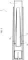
- indicated with 2 is the body of a roller clamp according to the invention, shown in its entirety with 1 in figure 11 and particularly designed for use in the medical field for regulating the flow of an infusion liquid, transfusion liquid or the like through an elastically deformable tubing, indicated with T still in figure 11 .
- the clamp 1 includes a roller or wheel indicated with 3 in figure 11 , both conveniently made by moulding plastic material.
- the body 2 has a general channel-like shape with a bottom wall 4 and two lateral walls respectively indicated with 5a and 5b.
- a lower tubular appendage 11 whose function is known, projects from the bottom wall 4.
- the inner face of the bottom wall 4, that is the face facing toward the internal of the body 2, has a generally flat surface, which will be indicated hereinafter as the clamping surface of the roller clamp 1.
- a longitudinal groove 7 which identifies, along the body 2 of the clamp 1, a flow regulation region and divides the clamping surface into two clamping surface longitudinal portions indicated with 6a and 6b, one respectively adjacent to the lateral wall 5a and the other to the lateral wall 5b.
- the longitudinal groove 7 formed along the clamping surface of the body 2 of the clamp has - in cross-section - a generally V or isosceles triangle shape, that is with lateral walls 7h, 7k oblique and diverging from the bottom wall 7j thereof.
- the longitudinal groove 7 extends not centrally, but asymmetrically along the body 2: more particularly it is closer to the lateral wall 5b, and therefore farther from the lateral wall 5a.
- the clamping surface portion 6a adjacent to the lateral wall 5a has a greater width than the clamping surface portion 6b adjacent to the lateral wall 5b.
- the longitudinal groove 7 has an initial end 7a and a terminal end 7b, and the cross-section thereof is decreasingly variable from the initial end 7a to the terminal end 7b.
- such cross-section of the groove 7 is substantially isosceles trapezium-shaped with smaller base, which defines the bottom wall 7j thereof, arranged on the bottom and an open larger base facing upwards.
- the longitudinal edges of the longitudinal groove 7 are connected to the clamping surface portions 6a, 6b through respective curved edges 7c, 7d. More precisely, such curved edges 7c, 7d are convex and have different curvature radii: the curvature radius of the curved surface 7c which connects the lateral wall 7h with the portion 6a of the regulation surface is larger, for example in the order of 0.3 mm., than the curvature radius of the curved surface 7d which connects the lateral wall 7k with the portion 6b of the regulation surface.
- the curvature radius of the curved surface 7d is for example in the order of 0.05 mm.: therefore, basically such surface 7d is almost sharp-edged.
- the initial end 7a of the longitudinal groove 7 is conveniently formed frontally with centring bevels 7e, 7f to facilitate the insertion of the flexible tubing T into the body 2 of the clamp 1.
- the two clamping surface portions 6a, 6b have ribs 8, that is thin grooves, which extend longitudinally beside the longitudinal groove 7 and they are conveniently arranged in an asymmetric and differentiated fashion, as better observable in figure 4 .
- the lateral walls 5a, 5b superiorly have respective inner grooves 9 which extend substantially parallelly to the clamping surface portions 6a, 6b.
- the two grooves 9 define respective longitudinal guides in which two axial pins 10 ( figure 11 ) protruding on opposite sides of the roller 3 are engaged in a freely rotatable and slidable manner.
- the roller 3 is therefore longitudinally slidable and rotatable along the guides 9 which delimit, together with the median longitudinal groove 7 and the clamping surface portions 6a, 6b, the aforementioned flow control region.
- the elastically deformable tubing T When using the elastically deformable tubing T, normally made of thermoplastic material, it is inserted into the body 2 through the front end thereof corresponding to the initial end 7a of the groove 7, between the clamping surface portions 6a, 6b and the roller 3. Should the roller 3 be positioned before the initial end 7a of the longitudinal groove 7, in the area shown in figure 7 , the tubing T is basically undeformed, therefore no flow regulation of the liquid therein occurs. In order to regulate the flow, the roller 3 must be moved at the initial end 7a and therefore moved towards the terminal end 7b of the longitudinal groove 7, progressively in the areas shown in figures 8-11 .
- the tubing T is progressively elastically deformed up to obtaining a substantially flat condition between the roller 3 and the clamping surface portions 6a, 6b, for example in the condition shown in figure 11 in which the narrow passage or lumen P whose width is directly proportional to the size of the cross-section of the longitudinal groove 7 is kept open.
- the size of the lumen P, and therefore the flow rate of the liquid through the tubing T is larger given that the roller 3 is positioned at and near the initial end 7a of the median longitudinal groove 7, and it decreases progressively as the roller 3 is approached to the terminal end 7b. Should the roller 3 be further moved beyond the terminal end 7b of the longitudinal groove 7, the tubing T is squeezed to fully flattened condition, therefore the flow of the liquid is shut off.
- the presence of the ribs 8 along the clamping surface portions 6a, 6b advantageously prevents the tubing T from moving laterally during the elastic deformation thereof carried out by moving the roller 3, also ensuring a more stable adaptation thereof.
- the groove 7 arranged asymmetrically has the aforementioned generally V-shaped cross-section and it is connected to the regulation surface 6a, 6b through the curved surfaces 7c, 7d with different curvatures, the tubing T is squeezed by the roller 3 against the clamping surface portions 6a, 6b even in an asymmetric and differentiated fashion, as exemplified in figure 11 . Therefore, the predominant part thereof, that is with greater extension, corresponding to the clamping surface portion 6a, is clamped and fully closed safely and reliably, while the lumen P is located at the part with smaller extension of the tubing T corresponding to the clamping surface portion 6b.
Landscapes
- Health & Medical Sciences (AREA)
- Heart & Thoracic Surgery (AREA)
- Animal Behavior & Ethology (AREA)
- Veterinary Medicine (AREA)
- Engineering & Computer Science (AREA)
- Anesthesiology (AREA)
- Biomedical Technology (AREA)
- Hematology (AREA)
- Life Sciences & Earth Sciences (AREA)
- General Health & Medical Sciences (AREA)
- Public Health (AREA)
- Pulmonology (AREA)
- Vascular Medicine (AREA)
- Fluid Mechanics (AREA)
- Physics & Mathematics (AREA)
- Infusion, Injection, And Reservoir Apparatuses (AREA)
- Vehicle Body Suspensions (AREA)
- Power Steering Mechanism (AREA)
- Valve Device For Special Equipments (AREA)
- Connection Of Plates (AREA)
Applications Claiming Priority (1)
| Application Number | Priority Date | Filing Date | Title |
|---|---|---|---|
| IT102021000027221A IT202100027221A1 (it) | 2021-10-22 | 2021-10-22 | Morsetto a rullino |
Publications (2)
| Publication Number | Publication Date |
|---|---|
| EP4169565A1 true EP4169565A1 (de) | 2023-04-26 |
| EP4169565B1 EP4169565B1 (de) | 2026-02-11 |
Family
ID=79270502
Family Applications (1)
| Application Number | Title | Priority Date | Filing Date |
|---|---|---|---|
| EP22199409.8A Active EP4169565B1 (de) | 2021-10-22 | 2022-10-03 | Rollenklemme |
Country Status (10)
| Country | Link |
|---|---|
| US (1) | US11975170B2 (de) |
| EP (1) | EP4169565B1 (de) |
| JP (1) | JP7840828B2 (de) |
| KR (1) | KR20230057970A (de) |
| CN (1) | CN115999041A (de) |
| AU (1) | AU2022246482A1 (de) |
| BR (1) | BR102022019589A2 (de) |
| CA (1) | CA3176583A1 (de) |
| IT (1) | IT202100027221A1 (de) |
| MX (1) | MX2022012928A (de) |
Cited By (1)
| Publication number | Priority date | Publication date | Assignee | Title |
|---|---|---|---|---|
| WO2025257685A1 (en) | 2024-06-13 | 2025-12-18 | Industrie Borla S.P.A. | Roller clamp |
Citations (6)
| Publication number | Priority date | Publication date | Assignee | Title |
|---|---|---|---|---|
| US3918675A (en) | 1972-08-30 | 1975-11-11 | Transcodan | Flow regulating device particularly for infusion and transfusion tubes |
| US4869721A (en) | 1986-02-12 | 1989-09-26 | Karpisek Ladislav Stephan | Flow regulator for liquids |
| US5014962A (en) | 1989-03-02 | 1991-05-14 | Marvin Adelberg | Clamp for regulating fluid flow through plastic tubing |
| US5259587A (en) * | 1992-06-08 | 1993-11-09 | Whitman Medical Corporation | Roller clamp |
| US6129330A (en) | 1998-09-09 | 2000-10-10 | Industrie Borla Spa | Roller clamp for regulating fluid flow through an elastically deformable tubing |
| DE102015202967A1 (de) * | 2015-02-19 | 2016-08-25 | Carl Zeiss Meditec Ag | Durchflussbegrenzer für eine Fluidleitung in einem Phakoemulsifikationssystem |
Family Cites Families (3)
| Publication number | Priority date | Publication date | Assignee | Title |
|---|---|---|---|---|
| JPS5844384B2 (ja) * | 1974-03-22 | 1983-10-03 | テルモ カブシキガイシヤ | クレンメ |
| US4725037A (en) | 1987-04-06 | 1988-02-16 | Marvin Adelberg | Shut-off mechanism for clamp for regulating flow through plastic tubing |
| JP2009232928A (ja) | 2008-03-26 | 2009-10-15 | Nippon Sherwood Medical Industries Ltd | ローラクランプ用カバー |
-
2021
- 2021-10-22 IT IT102021000027221A patent/IT202100027221A1/it unknown
-
2022
- 2022-09-27 CA CA3176583A patent/CA3176583A1/en active Pending
- 2022-09-28 BR BR102022019589-7A patent/BR102022019589A2/pt unknown
- 2022-10-03 EP EP22199409.8A patent/EP4169565B1/de active Active
- 2022-10-10 AU AU2022246482A patent/AU2022246482A1/en active Pending
- 2022-10-12 US US18/045,877 patent/US11975170B2/en active Active
- 2022-10-13 MX MX2022012928A patent/MX2022012928A/es unknown
- 2022-10-19 KR KR1020220134967A patent/KR20230057970A/ko active Pending
- 2022-10-21 JP JP2022169310A patent/JP7840828B2/ja active Active
- 2022-10-21 CN CN202211291719.6A patent/CN115999041A/zh active Pending
Patent Citations (6)
| Publication number | Priority date | Publication date | Assignee | Title |
|---|---|---|---|---|
| US3918675A (en) | 1972-08-30 | 1975-11-11 | Transcodan | Flow regulating device particularly for infusion and transfusion tubes |
| US4869721A (en) | 1986-02-12 | 1989-09-26 | Karpisek Ladislav Stephan | Flow regulator for liquids |
| US5014962A (en) | 1989-03-02 | 1991-05-14 | Marvin Adelberg | Clamp for regulating fluid flow through plastic tubing |
| US5259587A (en) * | 1992-06-08 | 1993-11-09 | Whitman Medical Corporation | Roller clamp |
| US6129330A (en) | 1998-09-09 | 2000-10-10 | Industrie Borla Spa | Roller clamp for regulating fluid flow through an elastically deformable tubing |
| DE102015202967A1 (de) * | 2015-02-19 | 2016-08-25 | Carl Zeiss Meditec Ag | Durchflussbegrenzer für eine Fluidleitung in einem Phakoemulsifikationssystem |
Cited By (1)
| Publication number | Priority date | Publication date | Assignee | Title |
|---|---|---|---|---|
| WO2025257685A1 (en) | 2024-06-13 | 2025-12-18 | Industrie Borla S.P.A. | Roller clamp |
Also Published As
| Publication number | Publication date |
|---|---|
| AU2022246482A1 (en) | 2023-05-11 |
| BR102022019589A2 (pt) | 2023-05-09 |
| CN115999041A (zh) | 2023-04-25 |
| MX2022012928A (es) | 2023-04-24 |
| US11975170B2 (en) | 2024-05-07 |
| IT202100027221A1 (it) | 2023-04-22 |
| JP2023063271A (ja) | 2023-05-09 |
| JP7840828B2 (ja) | 2026-04-06 |
| CA3176583A1 (en) | 2023-04-22 |
| KR20230057970A (ko) | 2023-05-02 |
| EP4169565B1 (de) | 2026-02-11 |
| US20230128026A1 (en) | 2023-04-27 |
Similar Documents
| Publication | Publication Date | Title |
|---|---|---|
| US6129330A (en) | Roller clamp for regulating fluid flow through an elastically deformable tubing | |
| EP4169565A1 (de) | Rollenklemme | |
| US6113062A (en) | Squeeze clamp | |
| US3802463A (en) | Flow control apparatus | |
| EP1691886B9 (de) | Schiebeklemme | |
| EP3648827B1 (de) | Kathetervorrichtungen mit blutkontrollsystemen und zugehörige verfahren | |
| US6857617B2 (en) | Roller pincher for setting the regulation cross-section of a flexible tubing | |
| US20030118687A1 (en) | Injection manifold having a valve pin guiding device | |
| AU622288B2 (en) | Clamp for regulating fluid flow through plastic tubing | |
| AU595001B2 (en) | A flow regulator for liquids | |
| US4034773A (en) | Method and apparatus for metering fluids | |
| US4856755A (en) | Flow control | |
| US8313081B2 (en) | Parallel-acting roller clamp for intravenous administration set | |
| CA1095011A (en) | Intravenous tubing clamping device | |
| US4811928A (en) | Control clamp for infusion hoses | |
| US4066238A (en) | Means for controlling fluid flow | |
| EP3952974B1 (de) | Urinkatheterdrainageelemente mit begrenzung der flüssigkeitsdrainage | |
| EP2012023A1 (de) | Plattenklemme | |
| NZ793100A (en) | Roller clamp | |
| CN219921732U (zh) | 通用流量限制器组件与静脉注射套件 | |
| JP4478094B2 (ja) | プラスチック成形ローラ型締め付けクランプ | |
| WO2025257685A1 (en) | Roller clamp | |
| DE10349761A1 (de) | Vorrichtung zur Regulierung der Strömung in Schlauchleitungen, insbesondere für enterale Überleitsysteme, und enterales Überleitsystem mit einer derartigen Vorrichtung | |
| EP3357526B1 (de) | Einstechdorn | |
| CN117750994A (zh) | 具有滚轮夹的输液设备 |
Legal Events
| Date | Code | Title | Description |
|---|---|---|---|
| PUAI | Public reference made under article 153(3) epc to a published international application that has entered the european phase |
Free format text: ORIGINAL CODE: 0009012 |
|
| STAA | Information on the status of an ep patent application or granted ep patent |
Free format text: STATUS: THE APPLICATION HAS BEEN PUBLISHED |
|
| AK | Designated contracting states |
Kind code of ref document: A1 Designated state(s): AL AT BE BG CH CY CZ DE DK EE ES FI FR GB GR HR HU IE IS IT LI LT LU LV MC ME MK MT NL NO PL PT RO RS SE SI SK SM TR |
|
| P01 | Opt-out of the competence of the unified patent court (upc) registered |
Effective date: 20230615 |
|
| STAA | Information on the status of an ep patent application or granted ep patent |
Free format text: STATUS: REQUEST FOR EXAMINATION WAS MADE |
|
| 17P | Request for examination filed |
Effective date: 20231003 |
|
| RAV | Requested validation state of the european patent: fee paid |
Extension state: TN Effective date: 20231003 Extension state: MA Effective date: 20231003 |
|
| RAX | Requested extension states of the european patent have changed |
Extension state: BA Payment date: 20231003 |
|
| RBV | Designated contracting states (corrected) |
Designated state(s): AL AT BE BG CH CY CZ DE DK EE ES FI FR GB GR HR HU IE IS IT LI LT LU LV MC ME MK MT NL NO PL PT RO RS SE SI SK SM TR |
|
| GRAP | Despatch of communication of intention to grant a patent |
Free format text: ORIGINAL CODE: EPIDOSNIGR1 |
|
| STAA | Information on the status of an ep patent application or granted ep patent |
Free format text: STATUS: GRANT OF PATENT IS INTENDED |
|
| RIC1 | Information provided on ipc code assigned before grant |
Ipc: A61M 39/28 20060101AFI20250820BHEP |
|
| INTG | Intention to grant announced |
Effective date: 20250909 |
|
| GRAS | Grant fee paid |
Free format text: ORIGINAL CODE: EPIDOSNIGR3 |
|
| GRAA | (expected) grant |
Free format text: ORIGINAL CODE: 0009210 |
|
| STAA | Information on the status of an ep patent application or granted ep patent |
Free format text: STATUS: THE PATENT HAS BEEN GRANTED |
|
| AK | Designated contracting states |
Kind code of ref document: B1 Designated state(s): AL AT BE BG CH CY CZ DE DK EE ES FI FR GB GR HR HU IE IS IT LI LT LU LV MC ME MK MT NL NO PL PT RO RS SE SI SK SM TR |
|
| REG | Reference to a national code |
Ref country code: CH Ref legal event code: F10 Free format text: ST27 STATUS EVENT CODE: U-0-0-F10-F00 (AS PROVIDED BY THE NATIONAL OFFICE) Effective date: 20260211 Ref country code: GB Ref legal event code: FG4D |
|
| REG | Reference to a national code |
Ref country code: DE Ref legal event code: R096 Ref document number: 602022030080 Country of ref document: DE |
|
| REG | Reference to a national code |
Ref country code: IE Ref legal event code: FG4D |