EP4169621A1 - Dispositif supporté par hélice pour le nettoyage, le revêtement, le scellement et/ou le laquage de façades de bâtiments, façades en verre, toits, parois intérieures de tunnels et similaires - Google Patents
Dispositif supporté par hélice pour le nettoyage, le revêtement, le scellement et/ou le laquage de façades de bâtiments, façades en verre, toits, parois intérieures de tunnels et similaires Download PDFInfo
- Publication number
- EP4169621A1 EP4169621A1 EP22199446.0A EP22199446A EP4169621A1 EP 4169621 A1 EP4169621 A1 EP 4169621A1 EP 22199446 A EP22199446 A EP 22199446A EP 4169621 A1 EP4169621 A1 EP 4169621A1
- Authority
- EP
- European Patent Office
- Prior art keywords
- spray unit
- base body
- propeller
- painting
- spray
- Prior art date
- Legal status (The legal status is an assumption and is not a legal conclusion. Google has not performed a legal analysis and makes no representation as to the accuracy of the status listed.)
- Withdrawn
Links
Images


Classifications
-
- B—PERFORMING OPERATIONS; TRANSPORTING
- B05—SPRAYING OR ATOMISING IN GENERAL; APPLYING FLUENT MATERIALS TO SURFACES, IN GENERAL
- B05B—SPRAYING APPARATUS; ATOMISING APPARATUS; NOZZLES
- B05B12/00—Arrangements for controlling delivery; Arrangements for controlling the spray area
- B05B12/08—Arrangements for controlling delivery; Arrangements for controlling the spray area responsive to condition of liquid or other fluent material to be discharged, of ambient medium or of target ; responsive to condition of spray devices or of supply means, e.g. pipes, pumps or their drive means
- B05B12/12—Arrangements for controlling delivery; Arrangements for controlling the spray area responsive to condition of liquid or other fluent material to be discharged, of ambient medium or of target ; responsive to condition of spray devices or of supply means, e.g. pipes, pumps or their drive means responsive to conditions of ambient medium or target, e.g. humidity, temperature position or movement of the target relative to the spray apparatus
- B05B12/124—Arrangements for controlling delivery; Arrangements for controlling the spray area responsive to condition of liquid or other fluent material to be discharged, of ambient medium or of target ; responsive to condition of spray devices or of supply means, e.g. pipes, pumps or their drive means responsive to conditions of ambient medium or target, e.g. humidity, temperature position or movement of the target relative to the spray apparatus responsive to distance between spray apparatus and target
-
- B—PERFORMING OPERATIONS; TRANSPORTING
- B05—SPRAYING OR ATOMISING IN GENERAL; APPLYING FLUENT MATERIALS TO SURFACES, IN GENERAL
- B05B—SPRAYING APPARATUS; ATOMISING APPARATUS; NOZZLES
- B05B1/00—Nozzles, spray heads or other outlets, with or without auxiliary devices such as valves, heating means
- B05B1/28—Nozzles, spray heads or other outlets, with or without auxiliary devices such as valves, heating means with integral means for shielding the discharged liquid or other fluent material, e.g. to limit area of spray; with integral means for catching drips or collecting surplus liquid or other fluent material
-
- B—PERFORMING OPERATIONS; TRANSPORTING
- B05—SPRAYING OR ATOMISING IN GENERAL; APPLYING FLUENT MATERIALS TO SURFACES, IN GENERAL
- B05B—SPRAYING APPARATUS; ATOMISING APPARATUS; NOZZLES
- B05B12/00—Arrangements for controlling delivery; Arrangements for controlling the spray area
- B05B12/16—Arrangements for controlling delivery; Arrangements for controlling the spray area for controlling the spray area
- B05B12/18—Arrangements for controlling delivery; Arrangements for controlling the spray area for controlling the spray area using fluids, e.g. gas streams
-
- B—PERFORMING OPERATIONS; TRANSPORTING
- B05—SPRAYING OR ATOMISING IN GENERAL; APPLYING FLUENT MATERIALS TO SURFACES, IN GENERAL
- B05B—SPRAYING APPARATUS; ATOMISING APPARATUS; NOZZLES
- B05B13/00—Machines or plants for applying liquids or other fluent materials to surfaces of objects or other work by spraying, not covered by groups B05B1/00 - B05B11/00
- B05B13/02—Means for supporting work; Arrangement or mounting of spray heads; Adaptation or arrangement of means for feeding work
- B05B13/04—Means for supporting work; Arrangement or mounting of spray heads; Adaptation or arrangement of means for feeding work the spray heads being moved during spraying operation
- B05B13/0431—Means for supporting work; Arrangement or mounting of spray heads; Adaptation or arrangement of means for feeding work the spray heads being moved during spraying operation with spray heads moved by robots or articulated arms, e.g. for applying liquid or other fluent material to three-dimensional [3D] surfaces
-
- B—PERFORMING OPERATIONS; TRANSPORTING
- B64—AIRCRAFT; AVIATION; COSMONAUTICS
- B64D—EQUIPMENT FOR FITTING IN OR TO AIRCRAFT; FLIGHT SUITS; PARACHUTES; ARRANGEMENT OR MOUNTING OF POWER PLANTS OR PROPULSION TRANSMISSIONS IN AIRCRAFT
- B64D1/00—Dropping, ejecting, releasing or receiving articles, liquids, or the like, in flight
- B64D1/16—Dropping or releasing powdered, liquid, or gaseous matter, e.g. for fire-fighting
- B64D1/18—Dropping or releasing powdered, liquid, or gaseous matter, e.g. for fire-fighting by spraying, e.g. insecticides
-
- B—PERFORMING OPERATIONS; TRANSPORTING
- B64—AIRCRAFT; AVIATION; COSMONAUTICS
- B64U—UNMANNED AERIAL VEHICLES [UAV]; EQUIPMENT THEREFOR
- B64U10/00—Type of UAV
- B64U10/10—Rotorcrafts
- B64U10/13—Flying platforms
- B64U10/16—Flying platforms with five or more distinct rotor axes, e.g. octocopters
-
- B—PERFORMING OPERATIONS; TRANSPORTING
- B08—CLEANING
- B08B—CLEANING IN GENERAL; PREVENTION OF FOULING IN GENERAL
- B08B1/00—Cleaning by methods involving the use of tools
- B08B1/30—Cleaning by methods involving the use of tools by movement of cleaning members over a surface
- B08B1/32—Cleaning by methods involving the use of tools by movement of cleaning members over a surface using rotary cleaning members
- B08B1/34—Cleaning by methods involving the use of tools by movement of cleaning members over a surface using rotary cleaning members rotating about an axis parallel to the surface
-
- B—PERFORMING OPERATIONS; TRANSPORTING
- B08—CLEANING
- B08B—CLEANING IN GENERAL; PREVENTION OF FOULING IN GENERAL
- B08B9/00—Cleaning hollow articles by methods or apparatus specially adapted thereto
- B08B9/02—Cleaning pipes or tubes or systems of pipes or tubes
-
- B—PERFORMING OPERATIONS; TRANSPORTING
- B64—AIRCRAFT; AVIATION; COSMONAUTICS
- B64U—UNMANNED AERIAL VEHICLES [UAV]; EQUIPMENT THEREFOR
- B64U2101/00—UAVs specially adapted for particular uses or applications
- B64U2101/25—UAVs specially adapted for particular uses or applications for manufacturing or servicing
- B64U2101/28—UAVs specially adapted for particular uses or applications for manufacturing or servicing for painting or marking
-
- B—PERFORMING OPERATIONS; TRANSPORTING
- B64—AIRCRAFT; AVIATION; COSMONAUTICS
- B64U—UNMANNED AERIAL VEHICLES [UAV]; EQUIPMENT THEREFOR
- B64U2101/00—UAVs specially adapted for particular uses or applications
- B64U2101/25—UAVs specially adapted for particular uses or applications for manufacturing or servicing
- B64U2101/29—UAVs specially adapted for particular uses or applications for manufacturing or servicing for cleaning
-
- B—PERFORMING OPERATIONS; TRANSPORTING
- B64—AIRCRAFT; AVIATION; COSMONAUTICS
- B64U—UNMANNED AERIAL VEHICLES [UAV]; EQUIPMENT THEREFOR
- B64U2101/00—UAVs specially adapted for particular uses or applications
- B64U2101/45—UAVs specially adapted for particular uses or applications for releasing liquids or powders in-flight, e.g. crop-dusting
-
- B—PERFORMING OPERATIONS; TRANSPORTING
- B64—AIRCRAFT; AVIATION; COSMONAUTICS
- B64U—UNMANNED AERIAL VEHICLES [UAV]; EQUIPMENT THEREFOR
- B64U30/00—Means for producing lift; Empennages; Arrangements thereof
- B64U30/20—Rotors; Rotor supports
- B64U30/26—Ducted or shrouded rotors
Definitions
- the present invention relates to a propeller-assisted device for cleaning, coating, sealing and/or painting building facades, glass facades, roofs, inner walls of tunnels and the like.
- lacquering or “lacquering” is to be understood as meaning the application of lacquers as well as paints and glazes to a surface.
- devices for building cleaning and finishing have become known from the prior art, which have telescopic devices so that the respective user can advantageously carry out, for example, cleaning work and/or painting work from the ground at heights of up to 15 - 20 m, can carry out alone.
- such devices are limited in their maximum achievable height to those areas mentioned above.
- concave areas of the respective facade, as well as Roofs and the components arranged on them, such as photovoltaic systems, solar collectors, etc., which are also to be subjected to processing (cleaning, coating, painting, ...), can only be reached with difficulty or not at all.
- Drones i.e. unmanned flying objects, which are equipped with spray nozzles
- Drones have recently been used for work at even greater heights and in particularly inaccessible places on facades and on roofs, such as in particular in concave areas, outside corners of facades, roof gables, structures on roofs, etc are, via which they can apply liquids in flight to a surface to be treated.
- an aircraft for indoor and outdoor painting work has become known, consisting of an unmanned aircraft with a spray unit for paint, which is connected to a base station via a hose connection and via which the spray unit is supplied with electricity and spray material from the base station .
- the aircraft described there also has a control system and at least one sensor, with the aid of which the aircraft can be controlled and, in particular, its spray unit can be positioned with respect to a surface to be sprayed.
- the present invention is intended to provide a device for cleaning, coating, sealing and/or painting building facades, glass facades, roofs, inner walls of tunnels and the like, which makes it possible to clean particularly inaccessible places on facades and roofs, such as in particular concave areas, outside corners of facades, roof gables, structures on roofs, etc., for cleaning and/or finishing (coating, sealing, painting, etc.) without the respective user having to leave the floor himself.
- the present invention primarily aims at a high-quality, reproducible result of the surface treated with the device according to the invention.
- the device comprises at least one base body with at least one propeller connected to the base body; at least one spray unit pivotally connected to the base body via a pivot arm by means of a first pivot joint; at least one means for distance determination arranged on the base body, on the swivel arm and/or on the spray unit; and at least one base station which is connected to the base body via a supply hose.
- the device according to the invention advantageously enables the surface to be processed to be analyzed independently, the processing, in particular the cleaning, coating, sealing and/or painting of said surface to be adapted to its condition and the position of the device, preferably its swivel arm and/or during processing their spray unit in relation to the surface in such a way that a qualitatively optimal work result is always achieved.
- the at least one, preferably several, propellers connected to the base body advantageously make it possible to lift the base body together with the swivel arm, spray unit, supply hose and any other accessories from the ground, let it rise and fall in height and keep it in suspension.
- An embodiment of the invention is particularly preferred in which at least one further propeller is arranged on the spray unit, the propeller preferably being arranged pivotably on the spray unit.
- the at least one additional propeller on the spray unit advantageously makes it possible to balance out forces that act on the base body, the swivel arm and/or the spray unit and that arise in particular during the dispensing of material via the spray unit, and thereby ensure stable flight, in particular during a spraying process of the base body including swivel arm and spray unit.
- the at least one propeller is preferably pivotable, in particular pivotable via a cardanic suspension, operatively connected to the spray unit, whereby the propeller each can advantageously be rotated in such a way that it generates an optimal compensating thrust for the forces generated by the delivery of material via the spray unit.
- a more stable flight behavior in turn advantageously leads to a higher precision of the jet guidance of the spray unit and thus to a better quality of cleaning and/or coating or lacquering.
- the at least one propeller arranged on the spray unit also advantageously enables forces that occur as a result of a shift in the center of gravity of the system made up of the base body, swivel arm and spray unit, during or after a swivel movement of the swivel arm by a swivel angle ⁇ , as well as any counterforces which generated by the spray jet ejected from the spray unit and to stabilize the flight.
- the propellers are designed as impellers and/or double propellers.
- Impellers ie propellers with a ring-shaped or tubular casing, advantageously have a higher propeller efficiency in comparison to propellers without a casing.
- a double propeller in which two propellers arranged directly one behind the other preferably rotate in opposite directions, advantageously enables angular momentum to be equalized and thrust to be increased.
- the spray unit is pivotably connected to the pivot arm via at least one second pivot joint.
- the second swivel joint advantageously makes it possible, particularly in conjunction with the first swivel joint on the base body, by changing the swivel angle ⁇ of the spray unit, to change the angle of the spray jet to the object being sprayed, or always at 90° during a movement of the base body and/or the swivel arm ° to hold.
- the angle at which a material or spray jet hits an object in particular a building facade, can be set and/or kept constant independently of the current movement of the base body and/or the swivel arm become.
- the spray unit has at least one means for setting the distance with respect to the building facade, glass facade, the roof, the inner wall of a tunnel and the like
- the means for adjusting the distance preferably comprises a means for determining the distance and/or at least one sliding element for interacting with the building facade, glass facade, roof, inner wall of a tunnel and the like.
- a means for distance adjustment which can be designed in particular as a telescopic arm that can be extended and retracted by means of a spindle lifting motor or motors, advantageously enables the mechanical distance adjustment and control between the spray unit and the surface to be treated, resp. building facade.
- a sliding element which can preferably be configured by a roller and/or roller with 360° rotation possibility arranged at the end of the distance adjustment means opposite the spray unit, can advantageously ensure damage-free contact between the distance adjustment means and the surface to be processed , also during a movement of the device along said surface.
- an embodiment of the invention has proven itself in which at least one second motor is arranged on the swivel arm and is set up to swivel the spray unit relative to the swivel arm.
- a second motor arranged on the swivel arm advantageously allows exact automatic adjustment of the swivel angle ⁇ of the spray unit.
- the supply hose can be designed as a hose assembly, with at least one first material supply hose inside a cover, in particular for supplying a liquid, such as water, paints and/or other liquid finishing agents; at least one second material supply hose, in particular for supplying a gas, such as compressed air, and at least one cable for the power supply of the base body can be arranged.
- a supply hose designed as a hose assembly advantageously allows the main body or the spray unit to be supplied with different materials and energy, with the sheathing of the individual lines offering protection against damage on the one hand and on the other hand facilitating their handling during a flight by combining the various lines into a single structure.
- the supply hose as such and in particular the composite of the Material supply hoses and the cable can also advantageously exert traction on the base body during a flight, which can further increase the stabilization of the base body together with the swivel arm and spray unit in the air.
- the supply hose can preferably be rigidly connected to the base body via a connecting pipe arranged on the side of the base body facing the floor, in particular on the side of the base body opposite the swivel arm.
- the swivel arm is hollow, with at least one, preferably two, means for conveying material running or running inside the swivel arm and which is or are set up to take up material from the feed hose and to the spray unit transport.
- the means or means for conveying material can be made of a metal, for example aluminum, plastic and/or a carbon fiber composite material.
- a hollow swivel arm can advantageously supply the spray unit with various materials, such as water, soap solution, lacquers, paints, various other finishing and coating agents, but also with Supply compressed air and other gases as well as electricity. Said lines and cables are advantageously protected and can follow the movement inside the swivel arm.
- the spray unit comprises at least one receiving means for the reversible receiving and operative connection of accessories, in particular for receiving and operatively connecting a spray nozzle, a painting attachment and/or a rotary brush.
- a spray unit can advantageously be equipped with different attachments, types of nozzles and other tools, depending on the specific application.
- Said accessory can be connected quickly and easily via the at least one receiving means, which can be designed in particular as a quick-release system for the reversible connection of the accessory types mentioned.
- the painting attachment has at least one painting nozzle, which is set up to take up fluid material from the supply hose and to spray it in the form of a stream and/or a mist; at least one funnel, which encloses the painting nozzle and releases the jet and/or mist generated by the painting nozzle via its large funnel opening; and comprises at least one air nozzle, which is arranged at the edge of the large funnel opening and is set up to take up gaseous material, in particular compressed air, from the feed hose and discharge it to the outside.
- a painting attachment advantageously makes it possible to apply spray material, in particular paints, paints, but also other liquid finishing agents, specifically to the object to be treated, in particular a building facade, even in side winds, which can occur when using the device at great heights.
- the painting attachment also includes a sensor for measuring distance and layer thickness and/or a collecting device for collecting excess paint.
- a sensor for measuring the distance and layer thickness also enables precise control of the processing result, preferably in real time, and advantageously allows immediate correction while the device is in use.
- a collecting device for collecting excess paint advantageously enables the collected material to be reused and prevents contamination of regions of the building facade or the floor itself that are lower in relation to the current working position, i.e. towards the floor an indentation in the funnel of the painting attachment.
- two, four, six or preferably eight propellers can be arranged on the base body.
- a large number of propellers arranged on the base body advantageously enable the lifting and movement of systems consisting of base body, swivel arm, spray unit including any accessories and the supply hose with a total weight dependent on the respective climbing height, to climbing heights of up to 100 m.
- the base station comprises at least one mixing device, wherein the mixing device preferably comprises at least one tank for receiving at least one material, as well as a stirrer.
- the base station on the ground can advantageously also comprise at least one pump for pumping liquid material, at least one pump for pumping gaseous material, in particular for generating compressed air, and a power generator and/or a battery.
- a mixing device, as described, can in particular enable the rapid production of paint and/or varnish mixtures individually adapted to the respective customer requirements, with changes being able to be made while the device is still in use, for example based on the current customer impression of smaller sample areas that have already been processed.
- the device according to the invention makes it possible to reach exposed, crooked and generally inaccessible places on facades, roofs and the like for processing and ensures high-quality, reproducible work results, advantageously saving working time and costs and also increasing occupational safety for the user or users, since work by people at greater heights can be dispensed with.
- an embodiment of a propeller-based device 1 according to the invention is shown in use in a side view.
- a propeller-assisted device 1 for cleaning, coating, sealing and/or painting building facades 7, glass facades, roofs, inner walls of tunnels and the like comprises at least one base body 11 with at least one propeller 111 connected to the base body 11; at least one spray unit 13, which is pivotably connected to the base body 11 via a pivot arm 12 by means of a first pivot joint 113; at least one means for distance determination 16 or 134 arranged on the base body 11, on the swivel arm 12 and/or on the spray unit 13; and at least one base station 3, which is connected to the base body 11 via a supply hose 2.
- means 16 for determining the distance on the connecting struts to the propellers 111 and means 134 for determining the distance on means 133 for adjusting the distance of the spray unit 13 are shown as examples.
- the at least one means for distance determination 16 or 134 can be embodied in particular as a laser range finder, sonar and/or radar sensor.
- the pivoting arm 12 can preferably be arranged centrally on the base body 11 and can be pivoted up and down with respect to the base body 11, with the pivoting arm 12 sweeping over a pivoting angle ⁇ .
- a first motor 112 can preferably be arranged on the base body 11 to control the movement of the swivel arm 12 and is set up to interact with the swivel arm 12 and/or with the first swivel joint 113 .
- propeller 111 namely in particular two, four, six or preferably eight propellers 111 can advantageously be arranged on the base body 11, which can preferably be firmly connected to the base body 11 via connecting struts.
- a larger number of propellers 111 connected to the base body 11 advantageously increases the carrying capacity of the base body 11, so that, for example, heavier accessories can be connected to the spray unit 13 of the device 1 and also generally stabilizes the flight characteristics of the device 1.
- the propellers 111 connected to the base body 11 via connecting struts can preferably be arranged around the base body 11 in such a way that a silhouette that is comparatively narrow with respect to the orientation of the swivel arm 12 is produced.
- eight propellers 111 are arranged around the base body 11, with four of them being fixed on one side and the other four on the other side with respect to the pivot plane of the pivot arm 12.
- the four propellers 111 on one side can preferably be positioned one behind the other on a line and relatively close to the base body with respect to the pivot plane of the pivot arm 12, so that the transverse extent of the base body 111 including the propellers 111, i.e.
- the extent perpendicular to the pivoting plane of the pivoting arm 12 advantageously only lies in a range of 35 to 90 cm.
- Such a narrow design advantageously increases the accessibility of facade outside corners, roof gables and the like.
- the base body 11 is connected to a base station 3 via the supply hose 2 and is supplied by it with liquid and/or gaseous material and with electricity.
- the base station 3 on the ground can in particular comprise at least one pump for pumping liquid material, such as water, washing solutions, paints, varnishes, coating and/or finishing agents, and at least one pump for pumping gaseous material, in particular for generating compressed air .
- a generator and/or a battery can also advantageously be part of the base station 3, so that the base body 11, the first motor 112, the swivel arm 12 and/or the spray attachment 13 together with any accessories arranged thereon can be supplied with electricity.
- the base station 3 can also include at least one mixing device, wherein the mixing device preferably includes at least one tank for receiving at least one material and a stirrer (not shown here).
- a mixing device advantageously makes it possible to implement change requests, in particular special color requests by the customer, which only arise during the processing of an object or a facade, immediately or on site.
- the feed hose 2 can preferably be designed as a hose assembly, with at least one first material feed hose 21 inside an envelope, in particular for feeding in a liquid, such as water, paints and/or other liquid finishing agents; at least one second material supply hose 22, in particular for supplying a gas, such as compressed air; and at least one cable 23 for the power supply of the base body 11 can be arranged.
- a liquid such as water, paints and/or other liquid finishing agents
- second material supply hose 22 in particular for supplying a gas, such as compressed air
- at least one cable 23 for the power supply of the base body 11 can be arranged.
- the feed hose 2 can also advantageously exert tension on the base body 11 due to its weight and thereby further stabilize the base body 11 in the air.
- the supply hose 2 is rigidly connected to the base body 11 on the underside of the base body 11 via a connecting pipe 14, as shown in FIG 1 implied.
- the spraying process on the base body 11 acting counter-impulse can then be advantageously derived via the connecting pipe 14 and the supply hose 2 and an undesirable increase in distance to the surface to be treated, here the building facade 7, triggered by the spraying process itself, can advantageously be avoided.
- the pivoting arm 12 can preferably be hollow, with at least one, preferably two, means for conveying material running inside the pivoting arm 12 , which is set up to receive material from the feed hose 2 and to transport it to the spray unit 13 .
- At least one additional line for electrical current, in particular at least one additional cable, can of course also run within the hollow swivel arm 12, which conducts the electrical current provided via the supply hose 2 or the cable 23 running in it from the base station 3 to the spray unit 13 .
- the spray unit 13 itself preferably comprises at least one receiving means 132 for the reversible receiving and operative connection of accessories, in particular for receiving and operatively connecting a spray nozzle 6, a painting attachment 4 and/or a rotary brush 5, and can preferably comprise at least one additional propeller 131.
- 1 illustrates this equipment as an example, with the configuration shown here showing two propellers 131 positioned one above the other, which are arranged on the spray unit 13 via connecting struts on the opposite side of a spray nozzle 6, which is operatively connected to the spray unit 13 via the receiving means 132.
- the at least one propeller 131, or the two propellers 131 shown here, are preferably pivotable, in particular pivotable via a cardanic suspension, operatively connected to the spray unit 13, as a result of which the propeller or propellers 131 can advantageously be rotated in such a way that they have an optimal compensating thrust to the forces generated by the dispensing of material via the spray unit 13.
- the propeller or propellers 131 can be directed away from the spray nozzle 6 of the spray unit 13 in particular.
- the propeller or propellers 131 on the spray unit 13, as well as the propeller or propellers 111 on the base body can be designed as an impeller (as shown here) and/or as a double propeller (not shown here).
- One or more additional propellers 131 on the spray unit 13 advantageously make it possible Forces that act on the base body 11, the swivel arm 12 and/or the spray unit 13 and that arise in particular during the dispensing of material via the spray unit 13, and thereby ensure a stable flight of the base body 11 together with the swivel arm 12 and spray unit 13, in particular during a spraying process to ensure.
- the propeller(s) 131 arranged on the spray unit 13 advantageously also enables forces that occur as a result of a shift in the center of gravity of the system made up of the base body 11, swivel arm 12 and spray unit 13, during or after a swiveling movement of the swivel arm 12 by a swivel angle ⁇ , as well as to compensate for any opposing forces generated by the spray jet ejected from the spray unit 13 and to stabilize the flight.
- the means(s) 16 for determining the distance on the base body 11 or on the swivel arm 12 with the means(s) 134 for determining the distance on the spray unit 13 and/or in conjunction with a sensor 44 for distance and layer thickness measurement on a painting attachment 4, in particular the rotational speeds of the propellers 111 on the base body 11 and/or swivel arm 12 or the propeller 131 on the spray unit 13 can be individually controlled in order to determine the position and distance of the device 1 from the surface to be treated in real time control and thus achieve high-quality work results at all times.
- the spray unit 13 can be pivotably connected to the pivot arm 12 via at least one second pivot joint 122 and can cover a pivot angle ⁇ .
- the spray unit 13 is preferably connected to the swivel arm 12 via the second swivel joint 122 in such a way that the spray unit 13, together with any propeller 131 arranged on it, can move unhindered from a position in which the end of the spray unit 13 facing the swivel arm 12 is above (towards the sky) of the longitudinal axis of the swing arm 12 to a position where the end of the spray unit 13 facing the swing arm 12 is below (towards the ground) the longitudinal axis of the swing arm 12 can be swung along the swing angle ⁇ .
- the swivel arm 12 can either be articulated on one side of the spray unit 13 or, as in 2 shown, be configured in particular at the end facing the spray unit 13 fork-shaped, so that the spray unit 13 together with the propeller 131 at Pivoting process can be pivoted freely between the tines of the fork.
- at least one second motor 121 can preferably be arranged on the swivel arm 12 and is set up to swivel the spray unit 13 relative to the swivel arm 12 .
- a spray nozzle 6 that can be reversibly connected to the spray unit 13 via the receiving means 132 is particularly suitable for applying water, washing solutions and other cleaning agents to a roof or facade, both as part of high-pressure and low-pressure cleaning.
- the spray unit 13 can advantageously also comprise at least one, or as shown here two, means 133 for adjusting the distance with respect to the building facade 7, glass facade, the roof, the inner wall of a tunnel and the like, with the means 133 or means 133 for Distance adjustment preferably a means 134 for distance determination and / or at least one sliding element 135 for interaction with the building facade 7, glass facade, the roof, the inner wall of a tunnel and the like may include.
- the two means 133 for distance adjustment shown here as examples are designed as extendable and retractable telescopic arms, which are arranged pivotably on the spray unit 13 . In the extended state, they preferably extend on both sides of the spray nozzle 6, so that particularly stable support is ensured during the spraying process.
- the means 133 for distance adjustment in particular the telescopic arms, can be automatically adjusted in length, in particular with the aid of a motor, for example a spindle lifting motor, and advantageously enable the mechanical distance adjustment and control between the spray unit 13 and the surface to be treated, resp. Building facade 7.
- the or, as shown here, the sliding elements 135 can preferably be arranged by the end of the respective means 133, which is opposite to the spray unit 13, for distance adjustment. Rollers and/or rollers with a 360° rotation option are particularly suitable as sliding element 135, which can slide and/or roll along the surface to be machined and thus advantageously ensure damage-free contact between the respective means 133 for distance adjustment and the surface to be machined, too during a movement of the device 1 along said surface.
- the device 1 according to the invention can also be used advantageously for other work, in which the spray unit 13 is equipped with other accessories.
- the device 1 according to the invention, or its spray unit 13 can be equipped in particular with a painting attachment 4 as an accessory.
- a first embodiment of a painting attachment 4 is shown in use in a sectional side view.
- the painting attachment 4 preferably comprises at least one painting nozzle 42 which is set up to take up fluid material from the supply hose 2 and to spray it in the form of a jet and/or a mist.
- the painting attachment 4 can include at least one funnel 41 which encloses the painting nozzle 42 and releases the jet and/or mist generated by the painting nozzle 41 via its large funnel opening.
- the jet and/or mist generated by the painting nozzle 41 is indicated by dashed lines.
- the painting attachment 4 preferably includes at least one air nozzle 43, which is arranged on the edge of the large funnel opening and is set up to take up gaseous material, in particular compressed air, from the supply hose 2 and release it to the outside.
- FIG. 4 shows only a section through a funnel 41 shown as an example.
- the actual funnel 41 preferably completely encloses the painting nozzle 42, so that a spray jet that is generated can only exit through the large funnel opening on the side opposite the painting nozzle 42, whereby the spray jet or mist something can already be focused.
- a spray jet can very easily be deflected from the actual target point, which in turn can adversely affect the quality of the painting, coating and/or finishing.
- At least one air nozzle 43 can be arranged on the edge of the funnel 41, as already briefly described, which in particular blows out compressed air along the edge of the funnel 41, so that a kind of outer air curtain forms can advantageously prevent color drift caused by cross winds.
- Such an air curtain is in 4 - again as a section - by three short, closely spaced lines between building facade 7 and air nozzle 43 or edge of Funnel 41 indicated.
- the painting attachment 4 can also include a sensor 44 for measuring the distance and layer thickness, which advantageously checks the current position in particular of the spray unit 13 in relation to the treated surface but also the current treatment quality in real time and also transmits these results to the base station 3 .
- a correction of the mode of operation of the device 1, for example a change in distance and/or angle of the spray unit 13 with respect to the building facade 7, a change in the material composition, a change in the air flow ejected via the air nozzle 43, etc., can then advantageously be carried out either automatically or by a user be done on the ground.
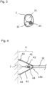
- FIG 5 shows a second embodiment of a painting attachment 4 with a collecting device 411 for collecting excess paint in a sectional side view.
- the collecting device 411 for collecting excess paint advantageously enables the collected material to be reused, wherein the collecting device 411 can preferably be operatively connected to the spray unit 13 in such a way that said collected material can be fed back into the spraying process.
- the collecting device 411 advantageously prevents the contamination of regions of the building facade 7 or the floor itself that are further down in relation to the current working position, i.e. towards the floor.
- the collecting device 411 can be designed in particular as a depression, specifically as a trough-shaped depression and/or a groove-shaped depression, in the funnel 41 of the painting attachment 4 .
- a rotary brush 5 can also be operatively connected to the spray unit 13 via the receiving means 132 .
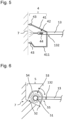
- 6 12 shows an embodiment of a rotary brush 5 in use in a sectional side view
- the rotary brush 5 can preferably comprise a brush head 53 which can be set in rotation by means of a motor 51 arranged on the rotary brush 5, preferably an electric motor which is supplied with power, for example via the cable 23 of the supply hose 2.
- the rotary brush 5 can also have at least one Include high-pressure nozzle 52, which can apply water and/or washing or cleaning liquid either directly to the facade 7 or the roof or first to the brush head 53.
- the at least one or preferably several high-pressure nozzles 52 can be directly or indirectly operatively connected to the material feed hoses 21 and/or 22 of the feed hose 2 via a tubing 54 .
- the stable and precise handling of the device 1 according to the invention advantageously allows said rotary brush 5 to be brought into direct contact with the object to be cleaned, in particular with the building facade 7 or the roof, and then not only by treatment with a spray jet, but also by a to clean mechanical action of the brush head 53 on the respective object.
- a means 55 for angle adjustment can also be arranged on the rotary brush 5, which is set up to rotate or shift the tubing 54 with respect to the longitudinal axis of the spray unit 13 and thereby adjust the spray angle of the high-pressure nozzles 52 to adjust with respect to the longitudinal axis of the spray unit 13.
- the means 55 for angle adjustment can preferably enable a spray angle of ⁇ 90° with respect to the longitudinal axis of the spray unit, with a spray angle of -90° being a spray direction directed vertically downwards (towards the ground) from the longitudinal axis of the spray unit 13, a spray angle of +90 ° describes a spray direction directed vertically upwards (towards the sky) from the longitudinal axis of the spray unit 13 and a spray angle of 0° describes a spray direction parallel to the longitudinal axis of the spray unit 13 and from the device 1 to the building facade 7 .
- the spray angle of the high-pressure nozzles 52 can also be changed in relation to the surface to be treated, so that such a configuration of the rotary brush 5 is particularly suitable for cleaning facade projections (as shown), but is also advantageous for cleaning solar collectors, photovoltaic systems and similar devices arranged on roofs.
- one or more feet 15 can finally be arranged on the base body for landing the base body 11, which can preferably be designed to be automatically folded out and in and the base body 11 together Swivel arm 12 and spray unit 13 offer a secure footing (cf 1 and 2 ).
- the present invention relates to a propeller-assisted device 1 for cleaning, coating, sealing and/or painting building facades, glass facades, roofs, inner walls of tunnels and the like, at least comprising: a base body 11 with at least one connected to the base body 11, propellers 111; at least one spray unit 13, which is pivotably connected to the base body 11 via a pivot arm 12 by means of a first pivot joint 113; at least one means for distance determination 16 or 134 arranged on the base body 11, on the swivel arm 12 and/or on the spray unit 13 and at least one base station 3, which is connected to the base body 11 via a supply hose 2.
- the device 1 according to the invention advantageously saves working time and costs and also increases occupational safety, since there is no need for people to work at greater heights.
Landscapes
- Engineering & Computer Science (AREA)
- Aviation & Aerospace Engineering (AREA)
- Life Sciences & Earth Sciences (AREA)
- Pest Control & Pesticides (AREA)
- Robotics (AREA)
- Mechanical Engineering (AREA)
- Remote Sensing (AREA)
- Spray Control Apparatus (AREA)
Applications Claiming Priority (1)
| Application Number | Priority Date | Filing Date | Title |
|---|---|---|---|
| DE102021005201.3A DE102021005201A1 (de) | 2021-10-19 | 2021-10-19 | Propeller-unterstützte Vorrichtung für die Reinigung, Beschichtung, Versiegelung und/oder Lackierung von Gebäudefassaden, Glasfassaden, Dächern, Innenwänden von Tunneln und dergleichen |
Publications (1)
| Publication Number | Publication Date |
|---|---|
| EP4169621A1 true EP4169621A1 (fr) | 2023-04-26 |
Family
ID=83594445
Family Applications (1)
| Application Number | Title | Priority Date | Filing Date |
|---|---|---|---|
| EP22199446.0A Withdrawn EP4169621A1 (fr) | 2021-10-19 | 2022-10-03 | Dispositif supporté par hélice pour le nettoyage, le revêtement, le scellement et/ou le laquage de façades de bâtiments, façades en verre, toits, parois intérieures de tunnels et similaires |
Country Status (2)
| Country | Link |
|---|---|
| EP (1) | EP4169621A1 (fr) |
| DE (1) | DE102021005201A1 (fr) |
Cited By (3)
| Publication number | Priority date | Publication date | Assignee | Title |
|---|---|---|---|---|
| US20210291981A1 (en) * | 2018-07-19 | 2021-09-23 | Aeronext Inc. | Flying object with elongated body |
| WO2025060212A1 (fr) * | 2023-09-21 | 2025-03-27 | 苏交科集团股份有限公司 | Détection de revêtement anticorrosion basée sur un véhicule aérien sans pilote et équipement intégré de réparation locale |
| EP4624329A1 (fr) * | 2024-03-26 | 2025-10-01 | Grupo Arena Presion, S.L. | Équipement pour nettoyer, peindre ou traiter des surfaces d'accès difficile |
Citations (4)
| Publication number | Priority date | Publication date | Assignee | Title |
|---|---|---|---|---|
| WO2013076711A2 (fr) * | 2013-03-07 | 2013-05-30 | Wasfi Alshdaifat | Appareil aérien de nettoyage des vitres |
| DE102014116821A1 (de) * | 2014-11-18 | 2016-05-19 | Joachim Schlechtriem | Unbemanntes Rotorfluggerät und Verfahren zum Bearbeiten einer Oberfläche |
| KR20160129786A (ko) * | 2016-05-27 | 2016-11-09 | 장민하 | 작업용 드론 |
| US10399676B2 (en) * | 2014-03-31 | 2019-09-03 | Working Drones, Inc. | Indoor and outdoor aerial vehicles for painting and related applications |
-
2021
- 2021-10-19 DE DE102021005201.3A patent/DE102021005201A1/de not_active Ceased
-
2022
- 2022-10-03 EP EP22199446.0A patent/EP4169621A1/fr not_active Withdrawn
Patent Citations (4)
| Publication number | Priority date | Publication date | Assignee | Title |
|---|---|---|---|---|
| WO2013076711A2 (fr) * | 2013-03-07 | 2013-05-30 | Wasfi Alshdaifat | Appareil aérien de nettoyage des vitres |
| US10399676B2 (en) * | 2014-03-31 | 2019-09-03 | Working Drones, Inc. | Indoor and outdoor aerial vehicles for painting and related applications |
| DE102014116821A1 (de) * | 2014-11-18 | 2016-05-19 | Joachim Schlechtriem | Unbemanntes Rotorfluggerät und Verfahren zum Bearbeiten einer Oberfläche |
| KR20160129786A (ko) * | 2016-05-27 | 2016-11-09 | 장민하 | 작업용 드론 |
Cited By (4)
| Publication number | Priority date | Publication date | Assignee | Title |
|---|---|---|---|---|
| US20210291981A1 (en) * | 2018-07-19 | 2021-09-23 | Aeronext Inc. | Flying object with elongated body |
| US11772793B2 (en) * | 2018-07-19 | 2023-10-03 | Aeronext Inc. | Flying object with elongated body |
| WO2025060212A1 (fr) * | 2023-09-21 | 2025-03-27 | 苏交科集团股份有限公司 | Détection de revêtement anticorrosion basée sur un véhicule aérien sans pilote et équipement intégré de réparation locale |
| EP4624329A1 (fr) * | 2024-03-26 | 2025-10-01 | Grupo Arena Presion, S.L. | Équipement pour nettoyer, peindre ou traiter des surfaces d'accès difficile |
Also Published As
| Publication number | Publication date |
|---|---|
| DE102021005201A1 (de) | 2023-04-20 |
Similar Documents
| Publication | Publication Date | Title |
|---|---|---|
| EP4169621A1 (fr) | Dispositif supporté par hélice pour le nettoyage, le revêtement, le scellement et/ou le laquage de façades de bâtiments, façades en verre, toits, parois intérieures de tunnels et similaires | |
| EP2040854B1 (fr) | Installation de mise en peinture et procédé de fonctionnement associé | |
| CN108355877A (zh) | 一种建筑装饰工程用管件喷漆装置 | |
| DE102014116821A1 (de) | Unbemanntes Rotorfluggerät und Verfahren zum Bearbeiten einer Oberfläche | |
| WO2000017086A1 (fr) | Dispositif pour realiser des travaux de reparation et de service, en particulier sur des pales de rotors de centralesoliennes | |
| US4978241A (en) | Roof gutter maintenance and cleaning apparatus | |
| DE4029027C2 (de) | Vorrichtung zur Wasserstrahlbearbeitung von Oberflächen mit einer Strahldüse und einer gelenkigen Strahldüsenhalterung | |
| DE4433925A1 (de) | Vorrichtung für eine Oberflächenbehandlung ausgedehnter, vorzugsweise gewölbter Oberflächen, insbesondere der Rumpfaußenflächen von Schiffen und Flugzeugen | |
| DE29502234U1 (de) | Oberflächen-Bearbeitungsvorrichtung für langgestreckte, ortsfest angebrachte Körper, insbesondere für Tragseile an Brücken | |
| DE102010029722A1 (de) | Farbauftragsystem | |
| DE3801003C2 (de) | Vorrichtung zur Beschickung von Tunnelschalungen mit Beton | |
| DE4433926A1 (de) | Vorrichtung für eine Oberflächenbehandlung ausgedehnter, vorzugsweise gewölbter Flächen, insbesondere der Rumpfaußenflächen von Flugzeugen und Schiffen | |
| DE4328536C2 (de) | Drehdüse | |
| DE102014000593A1 (de) | Vorrichtung für Strahlarbeiten | |
| DE19741126A1 (de) | Verfahren und Vorrichtung zum kontinuierlichen Beschichten von Mauerwerks- oder Betonoberflächen | |
| DE202010015610U1 (de) | Reinigungsvorrichtung für Solarpaneele | |
| EP2374387B1 (fr) | Dispositif de nettoyage pour le nettoyage des surfaces à hautes altitudes | |
| DE19936967C2 (de) | Hubschrauberzusatzgerät | |
| DE8990044U1 (de) | Manövriervorrichtung für eine Sprühdüse | |
| US12263505B2 (en) | Coating applicator | |
| DE102010051867A1 (de) | Reinigungsvorrichtung für Solarpaneele | |
| CN216196132U (zh) | 一种防水施工用沥青喷涂机 | |
| DE69812286T2 (de) | Fahrbare Arbeitsmasken, entweder motorangetrieben oder nicht, angeordnet für Hochdruckdistribution von Produkten wie Farben, Putz und dergleichen | |
| DE10308054A1 (de) | Vorrichtung zur Be- und Entschichtung von Rohren | |
| DE102019108022A1 (de) | Vorrichtung zur Farbauftragung auf eine Wand |
Legal Events
| Date | Code | Title | Description |
|---|---|---|---|
| PUAI | Public reference made under article 153(3) epc to a published international application that has entered the european phase |
Free format text: ORIGINAL CODE: 0009012 |
|
| STAA | Information on the status of an ep patent application or granted ep patent |
Free format text: STATUS: THE APPLICATION HAS BEEN PUBLISHED |
|
| AK | Designated contracting states |
Kind code of ref document: A1 Designated state(s): AL AT BE BG CH CY CZ DE DK EE ES FI FR GB GR HR HU IE IS IT LI LT LU LV MC ME MK MT NL NO PL PT RO RS SE SI SK SM TR |
|
| STAA | Information on the status of an ep patent application or granted ep patent |
Free format text: STATUS: THE APPLICATION IS DEEMED TO BE WITHDRAWN |
|
| 18D | Application deemed to be withdrawn |
Effective date: 20231027 |