EP4169644A1 - Schneidwerkzeug - Google Patents
Schneidwerkzeug Download PDFInfo
- Publication number
- EP4169644A1 EP4169644A1 EP21829122.7A EP21829122A EP4169644A1 EP 4169644 A1 EP4169644 A1 EP 4169644A1 EP 21829122 A EP21829122 A EP 21829122A EP 4169644 A1 EP4169644 A1 EP 4169644A1
- Authority
- EP
- European Patent Office
- Prior art keywords
- cutting
- oxide layer
- cutting tool
- straight line
- region
- Prior art date
- Legal status (The legal status is an assumption and is not a legal conclusion. Google has not performed a legal analysis and makes no representation as to the accuracy of the status listed.)
- Pending
Links
Images





Classifications
-
- B—PERFORMING OPERATIONS; TRANSPORTING
- B23—MACHINE TOOLS; METAL-WORKING NOT OTHERWISE PROVIDED FOR
- B23B—TURNING; BORING
- B23B27/00—Tools for turning or boring machines; Tools of a similar kind in general; Accessories therefor
- B23B27/14—Cutting tools of which the bits or tips or cutting inserts are of special material
- B23B27/148—Composition of the cutting inserts
-
- B—PERFORMING OPERATIONS; TRANSPORTING
- B23—MACHINE TOOLS; METAL-WORKING NOT OTHERWISE PROVIDED FOR
- B23C—MILLING
- B23C5/00—Milling-cutters
- B23C5/02—Milling-cutters characterised by the shape of the cutter
- B23C5/10—Shank-type cutters, i.e. with an integral shaft
-
- C—CHEMISTRY; METALLURGY
- C23—COATING METALLIC MATERIAL; COATING MATERIAL WITH METALLIC MATERIAL; CHEMICAL SURFACE TREATMENT; DIFFUSION TREATMENT OF METALLIC MATERIAL; COATING BY VACUUM EVAPORATION, BY SPUTTERING, BY ION IMPLANTATION OR BY CHEMICAL VAPOUR DEPOSITION, IN GENERAL; INHIBITING CORROSION OF METALLIC MATERIAL OR INCRUSTATION IN GENERAL
- C23C—COATING METALLIC MATERIAL; COATING MATERIAL WITH METALLIC MATERIAL; SURFACE TREATMENT OF METALLIC MATERIAL BY DIFFUSION INTO THE SURFACE, BY CHEMICAL CONVERSION OR SUBSTITUTION; COATING BY VACUUM EVAPORATION, BY SPUTTERING, BY ION IMPLANTATION OR BY CHEMICAL VAPOUR DEPOSITION, IN GENERAL
- C23C14/00—Coating by vacuum evaporation, by sputtering or by ion implantation of the coating forming material
- C23C14/06—Coating by vacuum evaporation, by sputtering or by ion implantation of the coating forming material characterised by the coating material
- C23C14/08—Oxides
- C23C14/081—Oxides of aluminium, magnesium or beryllium
-
- C—CHEMISTRY; METALLURGY
- C23—COATING METALLIC MATERIAL; COATING MATERIAL WITH METALLIC MATERIAL; CHEMICAL SURFACE TREATMENT; DIFFUSION TREATMENT OF METALLIC MATERIAL; COATING BY VACUUM EVAPORATION, BY SPUTTERING, BY ION IMPLANTATION OR BY CHEMICAL VAPOUR DEPOSITION, IN GENERAL; INHIBITING CORROSION OF METALLIC MATERIAL OR INCRUSTATION IN GENERAL
- C23C—COATING METALLIC MATERIAL; COATING MATERIAL WITH METALLIC MATERIAL; SURFACE TREATMENT OF METALLIC MATERIAL BY DIFFUSION INTO THE SURFACE, BY CHEMICAL CONVERSION OR SUBSTITUTION; COATING BY VACUUM EVAPORATION, BY SPUTTERING, BY ION IMPLANTATION OR BY CHEMICAL VAPOUR DEPOSITION, IN GENERAL
- C23C14/00—Coating by vacuum evaporation, by sputtering or by ion implantation of the coating forming material
- C23C14/06—Coating by vacuum evaporation, by sputtering or by ion implantation of the coating forming material characterised by the coating material
- C23C14/08—Oxides
- C23C14/083—Oxides of refractory metals or yttrium
-
- C—CHEMISTRY; METALLURGY
- C23—COATING METALLIC MATERIAL; COATING MATERIAL WITH METALLIC MATERIAL; CHEMICAL SURFACE TREATMENT; DIFFUSION TREATMENT OF METALLIC MATERIAL; COATING BY VACUUM EVAPORATION, BY SPUTTERING, BY ION IMPLANTATION OR BY CHEMICAL VAPOUR DEPOSITION, IN GENERAL; INHIBITING CORROSION OF METALLIC MATERIAL OR INCRUSTATION IN GENERAL
- C23C—COATING METALLIC MATERIAL; COATING MATERIAL WITH METALLIC MATERIAL; SURFACE TREATMENT OF METALLIC MATERIAL BY DIFFUSION INTO THE SURFACE, BY CHEMICAL CONVERSION OR SUBSTITUTION; COATING BY VACUUM EVAPORATION, BY SPUTTERING, BY ION IMPLANTATION OR BY CHEMICAL VAPOUR DEPOSITION, IN GENERAL
- C23C30/00—Coating with metallic material characterised only by the composition of the metallic material, i.e. not characterised by the coating process
- C23C30/005—Coating with metallic material characterised only by the composition of the metallic material, i.e. not characterised by the coating process on hard metal substrates
-
- B—PERFORMING OPERATIONS; TRANSPORTING
- B23—MACHINE TOOLS; METAL-WORKING NOT OTHERWISE PROVIDED FOR
- B23B—TURNING; BORING
- B23B2222/00—Materials of tools or workpieces composed of metals, alloys or metal matrices
- B23B2222/04—Aluminium
-
- B—PERFORMING OPERATIONS; TRANSPORTING
- B23—MACHINE TOOLS; METAL-WORKING NOT OTHERWISE PROVIDED FOR
- B23B—TURNING; BORING
- B23B2222/00—Materials of tools or workpieces composed of metals, alloys or metal matrices
- B23B2222/88—Titanium
-
- B—PERFORMING OPERATIONS; TRANSPORTING
- B23—MACHINE TOOLS; METAL-WORKING NOT OTHERWISE PROVIDED FOR
- B23B—TURNING; BORING
- B23B2224/00—Materials of tools or workpieces composed of a compound including a metal
- B23B2224/04—Aluminium oxide
-
- B—PERFORMING OPERATIONS; TRANSPORTING
- B23—MACHINE TOOLS; METAL-WORKING NOT OTHERWISE PROVIDED FOR
- B23B—TURNING; BORING
- B23B2226/00—Materials of tools or workpieces not comprising a metal
- B23B2226/12—Boron nitride
- B23B2226/125—Boron nitride cubic [CBN]
-
- B—PERFORMING OPERATIONS; TRANSPORTING
- B23—MACHINE TOOLS; METAL-WORKING NOT OTHERWISE PROVIDED FOR
- B23B—TURNING; BORING
- B23B2228/00—Properties of materials of tools or workpieces, materials of tools or workpieces applied in a specific manner
- B23B2228/04—Properties of materials of tools or workpieces, materials of tools or workpieces applied in a specific manner applied by chemical vapour deposition [CVD]
-
- B—PERFORMING OPERATIONS; TRANSPORTING
- B23—MACHINE TOOLS; METAL-WORKING NOT OTHERWISE PROVIDED FOR
- B23B—TURNING; BORING
- B23B2228/00—Properties of materials of tools or workpieces, materials of tools or workpieces applied in a specific manner
- B23B2228/08—Properties of materials of tools or workpieces, materials of tools or workpieces applied in a specific manner applied by physical vapour deposition [PVD]
-
- B—PERFORMING OPERATIONS; TRANSPORTING
- B23—MACHINE TOOLS; METAL-WORKING NOT OTHERWISE PROVIDED FOR
- B23B—TURNING; BORING
- B23B2228/00—Properties of materials of tools or workpieces, materials of tools or workpieces applied in a specific manner
- B23B2228/10—Coatings
- B23B2228/105—Coatings with specified thickness
-
- B—PERFORMING OPERATIONS; TRANSPORTING
- B23—MACHINE TOOLS; METAL-WORKING NOT OTHERWISE PROVIDED FOR
- B23C—MILLING
- B23C2210/00—Details of milling cutters
- B23C2210/12—Cross section of the cutting edge
- B23C2210/123—Bevelled cutting edges
-
- B—PERFORMING OPERATIONS; TRANSPORTING
- B23—MACHINE TOOLS; METAL-WORKING NOT OTHERWISE PROVIDED FOR
- B23C—MILLING
- B23C2210/00—Details of milling cutters
- B23C2210/12—Cross section of the cutting edge
- B23C2210/126—Rounded cutting edges
-
- B—PERFORMING OPERATIONS; TRANSPORTING
- B23—MACHINE TOOLS; METAL-WORKING NOT OTHERWISE PROVIDED FOR
- B23C—MILLING
- B23C2222/00—Materials of tools or workpieces composed of metals, alloys or metal matrices
- B23C2222/04—Aluminium
-
- B—PERFORMING OPERATIONS; TRANSPORTING
- B23—MACHINE TOOLS; METAL-WORKING NOT OTHERWISE PROVIDED FOR
- B23C—MILLING
- B23C2222/00—Materials of tools or workpieces composed of metals, alloys or metal matrices
- B23C2222/88—Titanium
-
- B—PERFORMING OPERATIONS; TRANSPORTING
- B23—MACHINE TOOLS; METAL-WORKING NOT OTHERWISE PROVIDED FOR
- B23C—MILLING
- B23C2224/00—Materials of tools or workpieces composed of a compound including a metal
- B23C2224/04—Aluminium oxide
-
- B—PERFORMING OPERATIONS; TRANSPORTING
- B23—MACHINE TOOLS; METAL-WORKING NOT OTHERWISE PROVIDED FOR
- B23C—MILLING
- B23C2226/00—Materials of tools or workpieces not comprising a metal
- B23C2226/12—Boron nitride
- B23C2226/125—Boron nitride cubic [CBN]
-
- B—PERFORMING OPERATIONS; TRANSPORTING
- B23—MACHINE TOOLS; METAL-WORKING NOT OTHERWISE PROVIDED FOR
- B23C—MILLING
- B23C2228/00—Properties of materials of tools or workpieces, materials of tools or workpieces applied in a specific manner
- B23C2228/04—Properties of materials of tools or workpieces, materials of tools or workpieces applied in a specific manner applied by chemical vapour deposition [CVD]
-
- B—PERFORMING OPERATIONS; TRANSPORTING
- B23—MACHINE TOOLS; METAL-WORKING NOT OTHERWISE PROVIDED FOR
- B23C—MILLING
- B23C2228/00—Properties of materials of tools or workpieces, materials of tools or workpieces applied in a specific manner
- B23C2228/08—Properties of materials of tools or workpieces, materials of tools or workpieces applied in a specific manner applied by physical vapour deposition [PVD]
-
- B—PERFORMING OPERATIONS; TRANSPORTING
- B23—MACHINE TOOLS; METAL-WORKING NOT OTHERWISE PROVIDED FOR
- B23C—MILLING
- B23C2228/00—Properties of materials of tools or workpieces, materials of tools or workpieces applied in a specific manner
- B23C2228/10—Coating
-
- B—PERFORMING OPERATIONS; TRANSPORTING
- B23—MACHINE TOOLS; METAL-WORKING NOT OTHERWISE PROVIDED FOR
- B23C—MILLING
- B23C2228/00—Properties of materials of tools or workpieces, materials of tools or workpieces applied in a specific manner
- B23C2228/49—Sintered
Definitions
- the present disclosure relates to a cutting tool.
- the present application claims a priority based on International Patent Application No. PCT/JP2020/024453 filed on June 22, 2020 , the entire contents of which are hereby incorporated by reference.
- Japanese Patent Laying-Open No. 2017-159380 discloses an end mill having a rake face in which a plurality of streaks (recesses) are formed.
- PTL 1 Japanese Patent Laying-Open No. 2017-159380
- a cutting tool includes a rake face, a flank face, and a cutting edge.
- the cutting edge is located between the rake face and the flank face.
- the cutting tool includes a substrate composed of a cubic boron nitride sintered material, and an oxide layer that covers the substrate and that constitutes part or whole of at least one of the rake face, the flank face, and the cutting edge.
- the oxide layer includes at least one element selected from a group consisting of titanium, aluminum, zirconium, and cobalt. A thickness of the oxide layer is 2 ⁇ m or less.
- the life of a cutting tool until breakage of a cutting edge can be extended.
- Fig. 1 is a schematic perspective view showing a configuration of a cutting tool 100 according to a first embodiment.
- Fig. 2 is a schematic side view showing the configuration of cutting tool 100 according to the first embodiment.
- cutting tool 100 according to the present embodiment is, for example, an end mill, and is constituted of a cutting edge portion 90, a joining portion 8, and a shank portion 7.
- Cutting edge portion 90 has first rake faces 4, first flank faces 3, second rake faces 15, second flank faces 30, outer peripheral cutting edges 72, bottom cutting edges 21, and a front end 58.
- Shank portion 7 has a rear end 59.
- Cutting edge portion 90 is fixed to shank portion 7 by joining portion 8.
- Joining portion 8 is a brazing material.
- Joining portion 8 is located between cutting edge portion 90 and shank portion 7.
- Cutting tool 100 is rotatable about an axis line A. From another viewpoint, it can be said that axis line A is a rotation axis of cutting tool 100.
- a material of cutting edge portion 90 includes, for example, a cubic boron nitride (cBN) sintered material.
- Shank portion 7 includes, for example, a cemented carbide. Examples of the cemented carbide include: a tungsten carbide (WC)-based cemented carbide; a cemented carbide including WC and Co; and a cemented carbide including WC as well as a carbonitride of Cr, Ti, Ta, Nb or the like added therein.
- WC tungsten carbide
- WC cemented carbide
- Co cemented carbide including WC as well as a carbonitride of Cr, Ti, Ta, Nb or the like added therein.
- Front end 58 of cutting tool 100 is a portion to face a workpiece.
- Rear end 59 of cutting tool 100 is a portion to face a tool for rotating cutting tool 100.
- Shank portion 7 is a portion to be attached to the tool for rotating cutting tool 100.
- a direction along axis line A is an axial direction.
- a direction perpendicular to the axial direction is a radial direction.
- a direction from front end 58 toward rear end 59 is referred to as rearward in the axial direction.
- a direction from rear end 59 toward front end 58 is referred to as forward in the axial direction.
- first flank face 3 is contiguous to first rake face 4.
- a ridgeline between first rake face 4 and first flank face 3 may constitute outer peripheral cutting edge 72.
- Second flank face 30 is contiguous to second rake face 15.
- a ridgeline between second rake face 15 and second flank face 30 constitutes bottom cutting edge 21.
- First rake face 4 is contiguous to second rake face 15.
- First rake face 4 is located rearward in the axial direction with respect to second rake face 15.
- First flank face 3 is contiguous to second flank face 30.
- First flank face 3 is located rearward in the axial direction with respect to second flank face 30.
- First chip discharging flutes 1 and second chip discharging flutes 2 are formed in cutting edge portion 90 of cutting tool 100.
- Each of first chip discharging flutes 1 is constituted of first rake face 4 and a first chip discharging surface 50.
- Each of second chip discharging flutes 2 is constituted of second rake face 15 and a second chip discharging surface 45.
- Second chip discharging surface 45 is contiguous to first chip discharging surface 50.
- First chip discharging flute 1 is provided in the form of a helix around axis line A.
- Second chip discharging flute 2 is contiguous to first chip discharging flute 1. In the direction along axis line A, the length of first chip discharging flute 1 is longer than the length of second chip discharging flute 2.
- Cutting tool 100 is, for example, a multi-edged rotary cutting tool 100.
- the number of outer peripheral cutting edges 72 is, for example, 2 or more.
- the lower limit of the number of outer peripheral cutting edges 72 is not particularly limited, but may be, for example, 4 or more or 8 or more.
- the upper limit of the number of outer peripheral cutting edges 72 is not particularly limited, but may be, for example, 20 or less or 16 or less.
- the number of outer peripheral cutting edges 72 is 5.
- the number of bottom cutting edges 21 may be the same as the number of outer peripheral cutting edges 72.
- Fig. 3 is a schematic cross sectional view when viewed along a line III-III of Fig. 2 .
- the cross section shown in Fig. 3 is a cross section perpendicular to the axis line.
- the plurality of first chip discharging flutes 1 are disposed in a peripheral direction (rotation direction R).
- the plurality of first flank faces 3 are disposed in the peripheral direction.
- the plurality of outer peripheral cutting edges 72 are disposed in the peripheral direction. That is, when assuming that a combination of first flank face 3, first chip discharging flute 1, and outer peripheral cutting edge 72 is one cutting component, a plurality of the cutting components are disposed in the peripheral direction.
- first chip discharging flute 1 is located forward in the rotation direction with respect to first flank face 3.
- first rake face 4 is located forward in the rotation direction with respect to outer peripheral cutting edge 72.
- first chip discharging surface 50 is located forward in the rotation direction with respect to first rake face 4.
- first flank faces 3 and first chip discharging flutes 1 are located alternately in rotation direction R.
- One end of each first flank face 3 may constitute outer peripheral cutting edge 72.
- the other end of first flank face 3 constitutes a tail portion 6.
- First flank face 3 may be contiguous to first rake face 4 at outer peripheral cutting edge 72.
- First flank face 3 is contiguous to first chip discharging surface 50 at tail portion 6.
- a length (first length L1) from axis line A to outer peripheral cutting edge 72 is longer than a length (second length L2) from axis line A to tail portion 6.
- Fig. 4 is an enlarged schematic view of a region IV in Fig. 3 .
- cutting tool 100 according to the first embodiment has cutting edge 72.
- Cutting edge 72 is located between rake face 4 and flank face 3.
- cutting edge 72 may have an arc shape that protrudes toward the outer side.
- Cutting edge 72 may be subjected to a chamfering process (honing process).
- Cutting tool 100 has a substrate 81.
- Substrate 81 is composed of a cubic boron nitride sintered material.
- Cutting tool 100 has a cutting region 22.
- Cutting region 22 is a region sandwiched between a first imaginary line 4b separated by 200 ⁇ m on rake face 4 from an imaginary ridgeline D and a second imaginary line 3b separated by 200 ⁇ m on flank face 3 from imaginary ridgeline D.
- Imaginary ridgeline D is a line formed by intersection of a plane (second extension plane C2) obtained by extending rake face 4 and a plane (first extension plane C1) obtained by extending flank face 3.
- cutting region 22 includes a first cutting region portion 4a, a second cutting region portion 3a, and cutting edge 72.
- First cutting region portion 4a is located at rake face 4.
- First cutting region portion 4a is contiguous to cutting edge 72.
- Second cutting region portion 3a is located at flank face 3.
- Second cutting region portion 3a is contiguous to cutting edge 72.
- Cutting edge 72 is a region sandwiched between first cutting region portion 4a and second cutting region portion 3a.
- Fig. 5 is a schematic plan view showing a configuration of cutting region 22.
- the schematic plan view shown in Fig. 5 is a diagram when viewed in a direction perpendicular to cutting region 22.
- substrate 81 includes cubic boron nitride grains 23 and a binder 25.
- Binder 25 is in contact with cubic boron nitride grains 23.
- Binder 25 may be sandwiched between two adjacent cubic boron nitride grains 23.
- Binder 25 may be provided to surround cubic boron nitride grains 23.
- Binder 25 includes at least one of aluminum (Al), titanium (Ti), chromium (Cr), zirconium (Zr), cobalt (Co), and tungsten (W).
- cutting tool 100 has an oxide layer 80.
- Oxide layer 80 is in contact with substrate 81.
- Oxide layers 80 may be provided to be separated from each other.
- Binder 25 may have a first binder portion 25a and a second binder portion 25b. Second binder portion 25b may be surrounded by oxide layer 80 when viewed in a direction perpendicular to cutting region 22. Second binder portion 25b is in contact with oxide layer 80. When viewed in the direction perpendicular to cutting region 22, first binder portion 25a may be separated from second binder portion 25b by oxide layer 80.
- First binder portion 25a may be in contact with each of oxide layer 80 and cubic boron nitride grain 23.
- Second binder portion 25b may be separated from cubic boron nitride grain 23.
- An ratio of an area occupied by oxide layer 80 in cutting region 22 is, for example, 20% or more and 80% or less. This is a value obtained by dividing the total area of oxide layer 80 in cutting region 22 by the area of cutting region 22.
- the lower limit of the ratio of the area occupied by oxide layer 80 in cutting region 22 is not particularly limited, but may be 25% or more, 30% or more, or 35% or more, for example.
- the upper limit of the ratio of the area occupied by oxide layer 80 in cutting region 22 is not particularly limited, but may be 75% or less, 70% or less, or 65% or less, for example.
- the ratio of the area occupied by oxide layer 80 in cutting region 22 is not particularly limited, but may be 20% or more and 75% or less, 20% or more and 70% or less, 20% or more and 65% or less, 25% or more and 80% or less, 30% or more and 80% or less, 35% or more and 80% or less, 25% or more and 75% or less, 25% or more and 70% or less, or 30% or more and 75% or less, for example.
- a method of measuring the ratio of the area occupied by oxide layer 80 in cutting region 22 will be described.
- a region including cutting region 22 is cut by a FIB (Focused Ion Beam) apparatus or WEDM
- a cross section polisher apparatus or the like is used to produce a sample for observing a cross section in a direction perpendicular to the cutting edge ridgeline.
- a scanning electron microscope (SEM) is used to observe a plurality of visual fields (about four visual fields) such that the length of the surface is 150 ⁇ m or more within a range of 200 ⁇ m from the cutting edge ridgeline (400 ⁇ m when summing up the region in the rake face direction and the region in the flank face direction).
- the magnification of the SEM is set to 50000x.
- a ratio of lumps of the oxide layer each having a thickness of 10 nm or more in the surface layer is defined as the area ratio of the oxide layer.
- An acceleration voltage is set to 5 kV.
- a region in which 10 at% or more of oxygen is detected through K or L rays is determined as the oxide layer.
- Oxide layer 80 includes at least one element selected from a group consisting of titanium (Ti), aluminum (Al), zirconium (Zr), and cobalt (Co).
- Oxide layer 80 is TiO, Al 2 O 3 , TiBNO, ZrO, AlBNO, CoO, CoWBO, or the like, for example.
- Oxide layer 80 may include two or more types of oxides. Specifically, oxide layer 80 may include at least two types of oxide films among TiO, Al 2 O 3 , TiBNO, ZrO, AlBNO, CoO, and CoWBO, for example.
- a type of oxide compound can be identified using a micro X-ray diffraction (XRD) apparatus or a transmission electron microscope (TEM).
- XRD micro X-ray diffraction
- TEM transmission electron microscope
- Oxide layer 80 constitutes part or whole of at least one of rake face 4, flank face 3, and cutting edge 72.
- Oxide layer 80 may constitute part or whole of rake face 4.
- Oxide layer 80 may constitute part or whole of flank face 3.
- Oxide layer 80 may constitute part or whole of cutting edge 72.
- Oxide layer 80 may constitute part or whole of cutting region 22.
- Fig. 6 is a schematic cross sectional view showing the configuration of cutting region 22.
- the schematic cross sectional view shown in Fig. 6 is perpendicular to axis line A.
- part of oxide layer 80 is exposed in cutting region 22.
- oxide layer 80 constitutes part of cutting region 22.
- Oxide layer 80 may be contiguous to binder 25.
- Oxide layer 80 may be formed by oxidizing part of the elements of binder 25.
- oxide layer 80 may include an element included in binder 25.
- Oxide layer 80 covers substrate 81.
- Oxide layer 80 may cover whole or part of cubic boron nitride grains 23.
- Oxide layer 80 may cover whole or part of binder 25.
- Oxide layer 80 may be in contact with cubic boron nitride grains 23 so as to cover part of cubic boron nitride grains 23. Part of cubic boron nitride grains 23 may be exposed from oxide layer 80.
- part of cubic boron nitride grains 23 may be exposed in cutting region 22. From another viewpoint, it can be said that cubic boron nitride grains 23 may constitute part of cutting region 22.
- Binder 25 may be located on a deeper side with respect to oxide layer 80. Part of binder 25 may be exposed in cutting region 22. From another viewpoint, it can be said that binder 25 may constitute part of cutting region 22.
- thickness T of oxide layer 80 is, for example, 30 nm or more and 300 nm or less. Thickness T of oxide layer 80 is a thickness in a direction perpendicular to a tangent to cutting region 22.
- the lower limit of thickness T of oxide layer 80 is not particularly limited, but may be 45 nm or more, 60 nm or more, or 75 nm or more, for example.
- the upper limit of thickness T of oxide layer 80 is not particularly limited, but may be, for example, 275 nm or less, 250 nm or less, or 225 nm or less.
- Thickness T of oxide layer 80 is not particularly limited but may be, for example, 30 nm or more and 275 nm or less, 30 nm or more and 250 nm or less, 30 nm or more and 225 nm or less, 45 nm or more and 300 nm or less, 60 nm or more and 300 nm or less, 75 nm or more and 300 nm or less, 45 nm or more and 275 nm or less, 60 nm or more and 250 nm or less.
- thickness T of oxide layer 80 can be measured by observing the cross section of cutting region 22 using a SEM. Specifically, after the region including cutting region 22 is cut by the FIB apparatus or WEDM, the cross section polisher apparatus or the like is used to produce the sample for observing the cross section in the direction perpendicular to the cutting edge ridgeline. Next, the SEM is used to observe the plurality of visual fields (about four visual fields) such that the length of the surface is 150 ⁇ m or more within a range of 200 ⁇ m from the cutting edge ridgeline (400 ⁇ m when summing up the region in the rake face direction and the region in the flank face direction).
- the magnification of the SEM is set to 50000x.
- the lumps of the oxide layer each having a thickness of 10 nm or more are identified.
- the identified lumps are analyzed using image analysis software (WINROOF). Specifically, the thicknesses of the lumps are measured at intervals of 100 nm, and the average value thereof is regarded as the thickness of oxide layer 80.
- Oxide layer 80 may be formed by irradiating the surface of substrate 81 with laser so as to oxidize part of the elements of binder 25. Specifically, the surface of substrate 81 in which cutting region 22 is formed is irradiated with laser.
- the laser is, for example, YAG laser.
- the wavelength of the laser is set to, for example, 1064 nm.
- the output of the laser is set to, for example, 5 W.
- the surface including cutting region 22 is irradiated with the laser using a Galvanometer scanner.
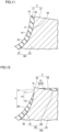
- FIG. 7 is an enlarged schematic cross sectional view showing the configuration of the first modification of cutting tool 100 according to the first embodiment.
- the schematic diagram shown in Fig. 7 corresponds to region IV in Fig. 3 .
- cutting edge 72 of cutting tool 100 may be acute.
- imaginary ridgeline D coincides with cutting edge 72.
- First cutting region portion 4a is a region sandwiched between cutting edge 72 and first imaginary line 4b separated by 200 ⁇ m on rake face 4 from cutting edge 72.
- Second cutting region portion 3a is a region sandwiched between cutting edge 72 and second imaginary line 3b separated by 200 ⁇ m on flank face 3 from cutting edge 72.
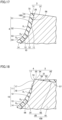
- FIG. 8 is an enlarged schematic cross sectional view showing the configuration of the second modification of cutting tool 100 according to the first embodiment.
- the schematic diagram shown in Fig. 8 corresponds to region IV in Fig. 3 .
- cutting edge 72 of cutting tool 100 may be a negative land having a flat shape.
- Cutting edge 72 may be inclined with respect to each of rake face 4 and flank face 3.
- First cutting region portion 4a is a region sandwiched between a boundary line between cutting edge 72 and rake face 4 and first imaginary line 4b separated by 200 ⁇ m on rake face 4 from imaginary ridgeline D.
- Second cutting region portion 3a is a region sandwiched between a boundary line between cutting edge 72 and flank face 3 and second imaginary line 3b separated by 200 ⁇ m on flank face 3 from imaginary ridgeline D.
- Cutting tool 100 according to the second embodiment is different from cutting tool 100 according to the first embodiment mainly in terms of such a configuration that oxide layer 80 covers the whole surface of substrate 81, and is the same as cutting tool 100 according to the first embodiment in terms of the other configurations.
- the configuration different from that of cutting tool 100 according to the first embodiment will be mainly described.
- Fig. 9 is a first schematic cross sectional view showing the configuration of cutting tool 100 according to the second embodiment.
- the schematic diagram shown in Fig. 9 corresponds to region IV in Fig. 3 .
- cutting edge portion 90 of cutting tool 100 according to the second embodiment has substrate 81 and oxide layer 80.
- Oxide layer 80 has, for example, a first oxide film 91 and a second oxide film 92.
- Substrate 81 has a first surface 10.
- First surface 10 faces rake face 4.
- First oxide film 91 has a second surface 56 and a third surface 55.
- Second surface 56 is in contact with first surface 10.
- Third surface 55 is located opposite to second surface 56.
- Third surface 55 constitutes at least part of rake face 4. In other words, the whole surface of third surface 55 may be rake face 4, or part of third surface 55 may be rake face 4.
- Substrate 81 has a fifth surface 31.
- Fifth surface 31 is contiguous to first surface 10.
- Fifth surface 31 faces flank face 3.
- a boundary between first surface 10 and fifth surface 31 is a first ridgeline 20.
- Second oxide film 92 constitutes at least part of flank face 3.
- Second oxide film 92 has a sixth surface 57 in contact with fifth surface 31, and a seventh surface 93 located opposite to sixth surface 57.
- Seventh surface 93 constitutes at least part of flank face 3. In other words, the whole surface of seventh surface 93 may be flank face 3, or part of seventh surface 93 may be flank face 3.
- first oxide film 91 may be contiguous to second oxide film 92.
- First oxide film 91 may be formed in one piece with second oxide film 92.
- the thickness of second oxide film 92 may be smaller than the thickness of first oxide film 91.
- the thickness of first oxide film 91 (hereinafter, also referred to as "first thickness") is, for example, 2 ⁇ m or less.
- the first thickness is a thickness of first oxide film 91 in a direction perpendicular to a tangent to first rake face 4.
- the first thickness may be, for example, 1 ⁇ m or less, or 0.1 ⁇ m or less.
- the lower limit of the first thickness is not particularly limited, but may be, for example, 0.01 ⁇ m or more.
- the thickness of second oxide film 92 (hereinafter, also referred to as "second thickness") is, for example, 2 ⁇ m or less.
- the second thickness is a thickness of second oxide film 92 in the direction perpendicular to the tangent to first flank face 3.
- the second thickness may be, for example, 1 ⁇ m or less, or 0.1 ⁇ m or less.
- the lower limit of the second thickness is not particularly limited, but may be, for example, 0.01 ⁇ m or more.
- first oxide film 91 and second oxide film 92 Next, a method of observing first oxide film 91 and second oxide film 92 will be described. First, cutting is performed in a cross section perpendicular to the axis line, thereby obtaining a measurement sample. The measurement sample is buried in a resin, and a CP (Cross Section Polish) process is performed onto the cross section.
- the composition of each of first oxide film 91 and second oxide film 92 can be specified using, for example, an energy dispersive X-ray spectroscopy (EDX) apparatus accompanied with a scanning electron microscope (SEM).
- EDX energy dispersive X-ray spectroscopy
- SEM scanning electron microscope
- JSM-7800F provided by JEOL
- EDX for example, an OctaneElect EDS system can be used.
- a measurement magnification can be set to, for example, 5000x.
- the thickness of first oxide film 91 is an average value of the thickness of first oxide film 91 at a position separated by a length of 0.1 ⁇ D1 from outer peripheral cutting edge 72 in a direction toward tail portion 6, the thickness of first oxide film 91 at a position separated by a length of 0.5 ⁇ D1 from outer peripheral cutting edge 72 in the direction toward tail portion 6, and the thickness of first oxide film 91 at a position separated by a length of 0.9 ⁇ D1 from outer peripheral cutting edge 72 in the direction toward tail portion 6.
- the thickness of second oxide film 92 is a thickness of second oxide film 92 at a position separated by a length of 0.5 ⁇ D2 from outer peripheral cutting edge 72 in the direction toward tail portion 6 (in other words, the center position of first flank face 3).
- Fig. 10 is a second schematic cross sectional view showing the configuration of cutting tool 100 according to the second embodiment.
- the schematic diagram shown in Fig. 10 corresponds to a region V in Fig. 3 .
- substrate 81 has an eighth surface 40.
- Eighth surface 40 faces first chip discharging surface 50.
- Eighth surface 40 is contiguous to each of first surface 10 and fifth surface 31. In the peripheral direction, eighth surface 40 is located between first surface 10 and fifth surface 31.
- a boundary between eighth surface 40 and fifth surface 31 constitutes a second ridgeline 5.
- First oxide film 91 may be in contact with eighth surface 40.
- First oxide film 91 may be in contact with second ridgeline 5.
- Second oxide film 92 may be in contact with second ridgeline 5.
- First oxide film 91 may be provided continuously from first ridgeline 20 to second ridgeline 5 in first chip discharging flute 1.
- Second oxide film 92 may be provided continuously from first ridgeline 20 to second ridgeline 5 in first flank face 3.
- First oxide film 91 may include at least one of aluminum, titanium, chromium, zirconium, cobalt, and tungsten.
- First oxide film 91 may be, for example, a coating film.
- the coating film may be formed by, for example, a CVD (Chemical Vapor Deposition) method or a PVD (Physical Vapor Deposition) method.
- First oxide film 91 may be formed by irradiating the surface of substrate 81 with laser so as to oxidize part of the elements of substrate 81.
- First oxide film 91 may be an oxide of part of the elements of substrate 81.
- first oxide film 91 may be an oxide of an element of binder 25 included in substrate 81.
- First oxide film 91 may include, for example, Al 2 O 3 , TiO 2 , CoO, W 2 O 3 , or the like.
- Second oxide film 92 may include at least one of aluminum, titanium, chromium, zirconium, cobalt, and tungsten. Second oxide film 92 may be, for example, a coating film.
- the coating film may be formed by, for example, a CVD method or a PVD method.
- Second oxide film 92 may be formed by irradiating the surface of substrate 81 with laser so as to oxidize part of the elements of substrate 81.
- Second oxide film 92 may be an oxide of part of the elements of substrate 81.
- second oxide film 92 may be an oxide of an element of binder 25 included in substrate 81.
- Second oxide film 92 may include, for example, Al 2 O 3 , TiO 2 , CoO, W 2 O 3 , or the like.
- Cutting tool 100 according to the third embodiment is different from cutting tool 100 according to the second embodiment in terms of such a configuration that no second oxide film 92 is included, and is the same as cutting tool 100 according to second embodiment in terms of the other configurations.
- the configuration different from that of cutting tool 100 according to the second embodiment will be mainly described.
- Fig. 11 is a partial schematic cross sectional view showing the configuration of cutting tool 100 according to the third embodiment.
- the region shown in Fig. 11 corresponds to region IV in Fig. 3 .
- first oxide film 91 may include a fourth surface 71 that connects second surface 56 to third surface 55.
- Fourth surface 71 of first oxide film 91 is provided along fifth surface 31 of substrate 81.
- a ridgeline between third surface 55 and fourth surface 71 constitutes outer peripheral cutting edge 72.
- No oxide film is formed on fifth surface 31. From another viewpoint, it can be said that fifth surface 31 of substrate 81 is exposed from first oxide film 91.
- Fourth surface 71 constitutes at least part of first flank face 3.
- First flank face 3 may include fourth surface 71 and fifth surface 31.
- Cutting tool 100 according to the fourth embodiment is different from cutting tool 100 according to the second embodiment in terms of such a configuration that first oxide film 91 is separated from second oxide film 92, and is the same as cutting tool 100 according to the second embodiment in terms of the other configurations.
- the configuration different from that of cutting tool 100 according to the second embodiment will be mainly described.
- Fig. 12 is a partial schematic cross sectional view showing the configuration of cutting tool 100 according to the fourth embodiment.
- the region shown in Fig. 12 corresponds to region IV in Fig. 3 .
- first oxide film 91 may be separated from second oxide film 92. Part of first surface 10 is exposed from first oxide film 91.
- First surface 10 has a first region 18 in contact with first oxide film 91, and a second region 17 contiguous to first region 18 and separated from first oxide film 91.
- Third surface 55 and second region 17 constitute rake face 4.
- fifth surface 31 is exposed from second oxide film 92.
- Fifth surface 31 has a third region 33 in contact with second oxide film 92, and a fourth region 34 contiguous to third region 33 and separated from second oxide film 92.
- Seventh surface 93 and fourth region 34 constitute flank face 3.
- a ridgeline between second region 17 and fourth region 34 constitute outer peripheral cutting edge 72.
- Second oxide film 92 may have a portion having a thickness that is increased in a direction further away from outer peripheral cutting edge 72.
- Cutting tool 100 according to the fifth embodiment is different from cutting tool 100 according to the second embodiment in terms of such a configuration that first surface 10 of substrate 81 is constituted of a plurality of straight line portions, and is the same as cutting tool 100 according to the second embodiment in terms of the other configurations.
- the configuration different from that of cutting tool 100 according to the second embodiment will be mainly described.
- Fig. 13 is a first schematic cross sectional view showing the configuration of cutting tool 100 according to the fifth embodiment.
- the region shown in Fig. 13 corresponds to region IV in Fig. 3 .
- Fig. 13 only substrate 81 is shown and no oxide film is shown.
- first surface 10 is constituted of a plurality of straight line portions.
- the plurality of straight line portions have, for example, a first straight line portion 11, a second straight line portion 12, a third straight line portion 13, and a fourth straight line portion 14.
- First straight line portion 11 is contiguous to first flank face 3.
- First straight line portion 11 is inclined with respect to fifth surface 31.
- a boundary between first straight line portion 11 and fifth surface 31 is a first ridgeline 20.
- Second straight line portion 12 is inclined with respect to first straight line portion 11.
- Second straight line portion 12 is contiguous to first straight line portion 11.
- Second straight line portion 12 is located opposite to fifth surface 31 with respect to first straight line portion 11. From another viewpoint, it can be said that first straight line portion 11 is located between second straight line portion 12 and fifth surface 31.
- Third straight line portion 13 is inclined with respect to second straight line portion 12.
- Third straight line portion 13 is contiguous to second straight line portion 12.
- Third straight line portion 13 is located opposite to first straight line portion 11 with respect to second straight line portion 12. From another viewpoint, it can be said that second straight line portion 12 is located between third straight line portion 13 and first straight line portion 11.
- Fourth straight line portion 14 is inclined with respect to third straight line portion 13.
- Fourth straight line portion 14 is contiguous to third straight line portion 13.
- Fourth straight line portion 14 is located opposite to second straight line portion 12 with respect to third straight line portion 13. From another viewpoint, it can be said that third straight line portion 13 is located between fourth straight line portion 14 and second straight line portion 12.
- An angle formed by two adjacent straight line portions of the plurality of straight line portions may be decreased in a direction further away from fifth surface 31.
- a first angle ⁇ 1 formed by first straight line portion 11 and second straight line portion 12 may be larger than a second angle ⁇ 2 formed by second straight line portion 12 and third straight line portion 13.
- Second angle ⁇ 2 formed by second straight line portion 12 and third straight line portion 13 may be larger than a third angle ⁇ 3 formed by third straight line portion 13 and fourth straight line portion 14.
- First angle ⁇ 1 is, for example, 140° or more and less than 180°.
- the lower limit of first angle ⁇ 1 is not particularly limited, but may be, for example, 150° or more, or 160° or more.
- the upper limit of first angle ⁇ 1 is not particularly limited, but may be, for example, 178° or less or 175° or less.
- a boundary between first straight line portion 11 and second straight line portion 12 is a first position X 1 .
- a boundary between second straight line portion 12 and third straight line portion 13 is a second position X 2 .
- a boundary between third straight line portion 13 and fourth straight line portion 14 is a third position X 3 .
- the length of first straight line portion 11 may be larger than the length of second straight line portion 12 (direct distance between first position X 1 and second position X 2 ).
- the length of second straight line portion 12 (direct distance between first position X 1 and second position X 2 ) may be larger than the length of third straight line portion 13 (direct distance between second position X 2 and third position X 3 ).
- a distance (first distance a1) between outer peripheral cutting edge 72 and first position X 1 may be the same as a distance (second distance a2) between first position X 1 and second position X 2 .
- the distance (second distance a2) between first position X 1 and second position X 2 may be the same as a distance (third distance a3) between second position X 2 and third position X 3 .
- Fig. 14 is a second schematic cross sectional view showing the configuration of cutting tool 100 according to the fifth embodiment.
- the region shown in Fig. 14 corresponds to region V in Fig. 3 .
- Fig. 14 only substrate 81 is shown and no oxide film is shown.
- eighth surface 40 may be constituted of, for example, a plurality of straight line portions.
- Eighth surface 40 has, for example, a fifth straight line portion 41, a sixth straight line portion 42, a seventh straight line portion 43, and an eighth straight line portion 44.
- Fifth straight line portion 41 is inclined with respect to fifth surface 31.
- Fifth straight line portion 41 is contiguous to second ridgeline 5.
- Sixth straight line portion 42 is inclined with respect to fifth straight line portion 41.
- Sixth straight line portion 42 is contiguous to fifth straight line portion 41.
- Sixth straight line portion 42 is located opposite to second ridgeline 5 with respect to fifth straight line portion 41. From another viewpoint, it can be said that fifth straight line portion 41 is located between sixth straight line portion 42 and second ridgeline 5.
- Seventh straight line portion 43 is inclined with respect to sixth straight line portion 42.
- Seventh straight line portion 43 is contiguous to sixth straight line portion 42.
- Seventh straight line portion 43 is located opposite to fifth straight line portion 41 with respect to sixth straight line portion 42.
- sixth straight line portion 42 is located between seventh straight line portion 43 and fifth straight line portion 41.
- Eighth straight line portion 44 is inclined with respect to seventh straight line portion 43.
- Eighth straight line portion 44 is contiguous to seventh straight line portion 43.
- Eighth straight line portion 44 is located opposite to sixth straight line portion 42 with respect to seventh straight line portion 43. From another viewpoint, it can be said that seventh straight line portion 43 is located between eighth straight line portion 44 and sixth straight line portion 42.
- a fourth angle ⁇ n-1 formed by fifth straight line portion 41 and sixth straight line portion 42 may be larger than a fifth angle ⁇ n-2 formed by sixth straight line portion 42 and seventh straight line portion 43.
- Fifth angle ⁇ n-2 formed by sixth straight line portion 42 and seventh straight line portion 43 may be larger than a sixth angle ⁇ n-3 formed by seventh straight line portion 43 and eighth straight line portion 44.
- a boundary between fifth straight line portion 41 and sixth straight line portion 42 is a fourth position X n-1 .
- a boundary between sixth straight line portion 42 and seventh straight line portion 43 is a fifth position X n-2 .
- a boundary between seventh straight line portion 43 and eighth straight line portion 44 is a sixth position X n-3 .
- the length of fifth straight line portion 41 (direct distance between second ridgeline 5 and fourth position X n-1 ) may be larger than the length of sixth straight line portion 42 (direct distance between fourth position X n-1 and fifth position X n-2 ).
- the length of sixth straight line portion 42 (direct distance between fourth position X n-1 and fifth position X n-2 ) may be larger than the length of seventh straight line portion 43 (direct distance between fifth position X n-2 and sixth position X n-3 ).
- a distance (fourth distance b1) between second ridgeline 5 and fourth position X n-1 may be the same as a distance (fifth distance b2) between fourth position X n-1 and fifth position X n-2 .
- the distance (fifth distance b2) between fourth position X n-1 and fifth position X n-2 may be the same as a distance (sixth distance b3) between fifth position X n-2 and sixth position X n-3 .
- Fig. 15 is a diagram showing a relation between an angle formed by two adjacent straight line portions and a position in the peripheral direction.
- first surface 10 the angle formed by the two adjacent straight line portions may be monotonously decreased in a direction from first ridgeline 20 toward eighth surface 40.
- first surface 10 may be constituted of, for example, 5 or more straight line portions.
- eighth surface 40 the angle formed by the two adjacent straight line portions may be monotonously decreased in a direction from second ridgeline 5 toward first surface 10.
- eighth surface 40 may be constituted of, for example, 5 or more straight line portions.
- the surface of substrate 81 facing first chip discharging flute 1 may be constituted of a plurality of straight line portions.
- the lower limit of the number of the straight line portions is not particularly limited, but may be, for example, 10 or more, or 20 or more.
- the upper limit of the number of the straight line portions is not particularly limited, but may be, for example, 50 or less, or 40 or less.
- a difference (angle difference B) between the maximum value of the angle formed by the two adjacent straight line portions and the minimum value of the angle formed by the two adjacent straight line portions in first surface 10 is, for example, 8° or more.
- the lower limit of angle difference B is not particularly limited, but may be, for example, 10° or more, or 12° or more.
- the upper limit of angle difference B is not particularly limited, but may be, for example, 30° or less.
- Fig. 16 is a partial schematic cross sectional view showing the configuration of cutting tool 100 according to the fifth embodiment.
- the region shown in Fig. 16 corresponds to region IV in Fig. 3 .
- cutting tool 100 in the cross section perpendicular to axis line A, has a substrate 81, a first oxide film 91, and a second oxide film 92.
- First surface 10 faces rake face 4.
- First oxide film 91 has a second surface 56 and a third surface 55.
- Second surface 56 is in contact with first surface 10.
- Third surface 55 is located opposite to second surface 56.
- Third surface 55 is rake face 4.
- Substrate 81 has a fifth surface 31.
- Fifth surface 31 is contiguous to first surface 10.
- Fifth surface 31 faces flank face 3.
- Second oxide film 92 constitutes flank face 3.
- Second oxide film 92 has a sixth surface 57 in contact with fifth surface 31, and a seventh surface 93 located opposite to sixth surface 57.
- Seventh surface 93 is flank face 3.
- rake face 4 may be constituted of a plurality of straight line portions.
- Rake face 4 may have a ninth straight line portion 51, a tenth straight line portion 52, an eleventh straight line portion 53, and a twelfth straight line portion 54.
- Ninth straight line portion 51 faces first straight line portion 11.
- Tenth straight line portion 52 faces second straight line portion 12.
- Eleventh straight line portion 53 faces third straight line portion 13.
- Twelfth straight line portion 54 faces fourth straight line portion 14.
- Ninth straight line portion 51 is contiguous to first flank face 3.
- Ninth straight line portion 51 is inclined with respect to first flank face 3.
- a boundary between ninth straight line portion 51 and first flank face 3 is outer peripheral cutting edge 72.
- Tenth straight line portion 52 is inclined with respect to ninth straight line portion 51.
- Tenth straight line portion 52 is contiguous to ninth straight line portion 51.
- Tenth straight line portion 52 is located opposite to first flank face 3 with respect to ninth straight line portion 51. From another viewpoint, it can be said that ninth straight line portion 51 is located between tenth straight line portion 52 and first flank face 3.
- Eleventh straight line portion 53 is inclined with respect to tenth straight line portion 52. Eleventh straight line portion 53 is contiguous to tenth straight line portion 52. Eleventh straight line portion 53 is located opposite to ninth straight line portion 51 with respect to tenth straight line portion 52. From another viewpoint, it can be said that tenth straight line portion 52 is located between eleventh straight line portion 53 and ninth straight line portion 51. Twelfth straight line portion 54 is inclined with respect to eleventh straight line portion 53. Twelfth straight line portion 54 is contiguous to eleventh straight line portion 53. Twelfth straight line portion 54 is located opposite to tenth straight line portion 52 with respect to eleventh straight line portion 53. From another viewpoint, it can be said that eleventh straight line portion 53 is located between twelfth straight line portion 54 and tenth straight line portion 52.
- Cutting tool 100 according to the sixth embodiment is different from cutting tool 100 according to the fifth embodiment in terms of such a configuration that no second oxide film 92 is included, and is the same as cutting tool 100 according to the fifth embodiment in terms of the other configurations.
- the configuration different from that of cutting tool 100 according to the fifth embodiment will be mainly described.
- Fig. 17 is a partial schematic cross sectional view showing the configuration of cutting tool 100 according to the sixth embodiment.
- the region shown in Fig. 17 corresponds to region IV in Fig. 3 .
- first oxide film 91 may further include a fourth surface 71 that connects second surface 56 to third surface 55.
- Fourth surface 71 of first oxide film 91 is provided along fifth surface 31 of substrate 81.
- a ridgeline between third surface 55 and fourth surface 71 constitutes outer peripheral cutting edge 72.
- No oxide film is formed on fifth surface 31. From another viewpoint, it can be said that fifth surface 31 of substrate 81 is exposed from first oxide film 91.
- Fourth surface 71 constitutes at least part of first flank face 3.
- First flank face 3 may include fourth surface 71 and fifth surface 31.
- Cutting tool 100 according to the seventh embodiment is different from cutting tool 100 according to the fifth embodiment in terms of such a configuration that first oxide film 91 is separated from second oxide film 92, and is the same as cutting tool 100 according to the fifth embodiment in terms of the other configurations.
- the configuration different from that of cutting tool 100 according to the fifth embodiment will be mainly described.
- Fig. 18 is a partial schematic cross sectional view showing the configuration of cutting tool 100 according to the seventh embodiment.
- the region shown in Fig. 18 corresponds to region IV in Fig. 3 .
- first oxide film 91 may be separated from second oxide film 92. Part of first surface 10 is exposed from first oxide film 91.
- First surface 10 has a first region 18 in contact with first oxide film 91, and a second region 17 contiguous to first region 18 and separated from first oxide film 91.
- Third surface 55 and second region 17 constitute rake face 4.
- Second region 17 may be part of first straight line portion 11.
- fifth surface 31 is exposed from second oxide film 92.
- Fifth surface 31 has a third region 33 in contact with second oxide film 92, and a fourth region 34 contiguous to third region 33 and separated from second oxide film 92.
- Second oxide film 92 has a sixth surface 57 in contact with fifth surface 31, and a seventh surface 93 located opposite to sixth surface 57. Seventh surface 93 and fourth region 34 constitute flank face 3.
- a ridgeline between second region 17 and fourth region 34 constitutes outer peripheral cutting edge 72.
- Second oxide film 92 may have a portion having a thickness that is increased in a direction further away from outer peripheral cutting edge 72.
- cutting tool 100 is, for example, a rotary cutting tool 100, more specifically, a multi-edged rotary cutting tool 100.
- Cutting tool 100 is, for example, an end mill, but is not limited to the end mill.
- Cutting tool 100 may be, for example, a reamer, a drill, or a tap.
- Cutting tool 100 may be, for example, a turning tool.
- Cutting tool 100 may be a throwaway insert.
- Fig. 19 is a schematic cross sectional view showing a state in which cutting is performed using cutting tool 100 according to the fifth embodiment.
- chip 61 of a workpiece 60 resulting from cutting by cutting edge 72 of cutting tool 100 is discharged with chip 61 being in contact with rake face 4.
- chip 61 may be melted and adhered to rake face 4.
- Cutting edge 72 may be broken due to the melting and adhesion of chip 61.
- Cutting tool 100 includes: substrate 81 composed of a cubic boron nitride sintered material; and oxide layer 80 that covers substrate 81 and that constitutes part or whole of at least one of rake face 4, flank face 3, and cutting edge 72.
- Oxide layer 80 includes at least one element selected from a group consisting of titanium, aluminum, zirconium, and cobalt. The thickness of oxide layer 80 is 2 ⁇ m or less. Thus, wear resistance of substrate 81 can be improved. Therefore, the life of cutting tool 100 until breakage of cutting edge 72 can be extended.
- the thickness of oxide layer 80 may be 30 nm or more and 300 nm or less.
- the thickness of oxide layer 80 is too thin, the function of improving lubricity by oxide layer 80 cannot be sufficiently exhibited, thus resulting in decreased wear resistance of cutting tool 100.
- oxide layer 80 is too thick, oxide layer 80 is likely to be detached.
- the cubic boron nitride sintered material is exposed, thus resulting in decreased wear resistance of cutting tool 100.
- the ratio of the area occupied by oxide layer 80 in cutting region 22 may be 20% or more and 80% or less, first imaginary line 4b being separated by 200 ⁇ m on rake face 4 from imaginary ridgeline D formed by intersection of the plane obtained by extending rake face 4 and the plane obtained by extending flank face 3, second imaginary line 3b being separated by 200 ⁇ m on flank face 3 from imaginary ridgeline D.
- first imaginary line 4b being separated by 200 ⁇ m on rake face 4 from imaginary ridgeline D formed by intersection of the plane obtained by extending rake face 4 and the plane obtained by extending flank face 3
- second imaginary line 3b being separated by 200 ⁇ m on flank face 3 from imaginary ridgeline D.
- first surface 10 of substrate 81 may be constituted of the plurality of straight line portions in the cross section perpendicular to axis line A.
- first surface 10 may have first straight line portion 11, second straight line portion 12 inclined with respect to first straight line portion 11 and contiguous to first straight line portion 11, and third straight line portion 13 inclined with respect to second straight line portion 12 and contiguous to second straight line portion 12.
- a clearance 9 is formed between curled chip 61 and a boundary between ninth straight line portion 51 facing first straight line portion 11 and tenth straight line portion 52 facing second straight line portion 12.
- a clearance 9 is formed between curled chip 61 and a boundary between tenth straight line portion 52 facing second straight line portion 12 and eleventh straight line portion 53 facing third straight line portion 13.
- cutting tools 100 of samples 1-1 to 1-12 were prepared.
- Each of cutting tools 100 of samples 1-1 to 1-12 is an end mill.
- substrate 81 is brazed to the front end of the shank portion composed of a cemented carbide.
- Substrate 81 is composed of a cBN sintered material.
- oxide layer 80 is formed in cutting region 22 (see Figs. 5 and 6 ).
- Oxide layer 80 is TiO.
- no oxide layer 80 is formed in cutting region 22.
- the thickness of oxide layer 80 was set to 0.015 ⁇ m, and the ratio of the area occupied by oxide layer 80 in cutting region 22 was set to 30%.
- the thickness of oxide layer 80 was set to 0.03 ⁇ m, and the ratio of the area occupied by oxide layer 80 in cutting region 22 was set to 48%.
- the thickness of oxide layer 80 was set to 0.06 ⁇ m, and the ratio of the area occupied by oxide layer 80 in cutting region 22 was set to 50%.
- the thickness of oxide layer 80 was set to 0.1 ⁇ m, and the ratio of the area occupied by oxide layer 80 in cutting region 22 was set to 56%.
- the thickness of oxide layer 80 was set to 0.25 ⁇ m, and the ratio of the area occupied by oxide layer 80 in cutting region 22 was set to 64%.
- the thickness of oxide layer 80 was set to 0.3 ⁇ m, and the ratio of the area occupied by oxide layer 80 in cutting region 22 was set to 68%.
- the thickness of oxide layer 80 was set to 0.7 ⁇ m, and the ratio of the area occupied by oxide layer 80 in cutting region 22 was set to 74%.
- the thickness of oxide layer 80 was set to 0.03 ⁇ m, and the ratio of the area occupied by oxide layer 80 in cutting region 22 was set to 14%.
- the thickness of oxide layer 80 was set to 0.03 ⁇ m, and the ratio of the area occupied by oxide layer 80 in cutting region 22 was set to 22%.
- the thickness of oxide layer 80 was set to 0.27 ⁇ m, and the ratio of the area occupied by oxide layer 80 in cutting region 22 was set to 80%.
- the thickness of oxide layer 80 was set to 0.26 ⁇ m, and the ratio of the area occupied by oxide layer 80 in cutting region 22 was set to 85%.
- workpiece 60 was processed using cutting tool 100 of each of samples 1-1 to 1-12.
- Workpiece 60 was SCM415.
- a cutting speed (Vc) was set to 300 mm/min.
- a feed amount (f) was set to 0.02 mm/t.
- An amount of cut (Ae) in the lateral direction was set to 0.2 mm.
- An amount of cut (Ap) in the axial direction was set to 3.0 mm.
- Coolant was a 20x diluted emulsion.
- Table 1 shows a breakage life when workpiece 60 was processed using cutting tool 100 of each of samples 1-1 to 1-12.
- the breakage life is a period of time from start of processing to breakage of cutting edge 72.
- the breakage life was 34 minutes or more and 88 minutes or less.
- the breakage life was 20 minutes. From the above results, it was proved that by providing oxide layer 80 in cutting region 22, the breakage life of cutting edge 72 was extended.
- the breakage life when workpiece 60 was processed using cutting tool 100 of each of samples 1-2 to 1-6 was longer than the breakage life when workpiece 60 was processed using cutting tool 100 of each of samples 1-1 and 1-7. From the above results, it was proved that by setting the thickness of oxide layer 80 to 0.03 ⁇ m or more and 0.3 ⁇ m or less, the breakage life of cutting edge 72 is extended.
- the breakage life when workpiece 60 was processed using cutting tool 100 of each of samples 1-2 and 1-9 was longer than the breakage life when workpiece 60 was processed using cutting tool 100 of sample 1-8.
- Oxide layers 80 of cutting tools 100 of samples 1-2, 1-8 and 1-9 have substantially the same thickness. From the above results, it was proved that by setting the ratio of the area occupied by oxide layer 80 in cutting region 22 to 20% or more, the breakage life of cutting edge 72 is extended.
- the breakage life when workpiece 60 was processed using cutting tool 100 of each of samples 1-5 and 1-10 was longer than the breakage life when workpiece 60 was processed using cutting tool 100 of sample 1-11.
- Oxide layers 80 of cutting tools 100 of samples 1-5, 1-10 and 1-11 have substantially the same thickness. From the above results, it was proved that by setting the ratio of the area occupied by oxide layer 80 in cutting region 22 to 80% or less, the breakage life of cutting edge 72 is extended.
- cutting tools 100 of samples 2-1 to 2-12 were prepared.
- Each of cutting tools 100 of samples 2-1 to 2-12 is an end mill.
- substrate 81 is brazed to the front end of the shank portion composed of a cemented carbide.
- Substrate 81 is composed of a cBN sintered material.
- oxide layer 80 is formed in cutting region 22 (see Figs. 5 and 6 ).
- Oxide layer 80 includes Al 2 O 3 , TiO, and TiBNO.
- no oxide layer 80 is formed in cutting region 22.
- the thickness of oxide layer 80 was set to 0.016 ⁇ m, and the ratio of the area occupied by oxide layer 80 in cutting region 22 was set to 32%.
- the thickness of oxide layer 80 was set to 0.03 ⁇ m, and the ratio of the area occupied by oxide layer 80 in cutting region 22 was set to 50%.
- the thickness of oxide layer 80 was set to 0.07 ⁇ m, and the ratio of the area occupied by oxide layer 80 in cutting region 22 was set to 45%.
- the thickness of oxide layer 80 was set to 0.11 ⁇ m, and the ratio of the area occupied by oxide layer 80 in cutting region 22 was set to 53%.
- the thickness of oxide layer 80 was set to 0.24 ⁇ m, and the ratio of the area occupied by oxide layer 80 in cutting region 22 was set to 58%.
- the thickness of oxide layer 80 was set to 0.3 ⁇ m, and the ratio of the area occupied by oxide layer 80 in cutting region 22 was set to 62%.
- the thickness of oxide layer 80 was set to 0.6 ⁇ m, and the ratio of the area occupied by oxide layer 80 in cutting region 22 was set to 72%.
- the thickness of oxide layer 80 was set to 0.03 ⁇ m, and the ratio of the area occupied by oxide layer 80 in cutting region 22 was set to 15%.
- the thickness of oxide layer 80 was set to 0.03 ⁇ m, and the ratio of the area occupied by oxide layer 80 in cutting region 22 was set to 21%.
- the thickness of oxide layer 80 was set to 0.25 ⁇ m, and the ratio of the area occupied by oxide layer 80 in cutting region 22 was set to 78%.
- the thickness of oxide layer 80 was set to 0.25 ⁇ m, and the ratio of the area occupied by oxide layer 80 in cutting region 22 was set to 85%.
- workpiece 60 was processed using cutting tool 100 of each of samples 2-1 to 2-12.
- Workpiece 60 was SCM416.
- a cutting speed (Vc) was set to 300 mm/min.
- a feed amount (f) was set to 0.02 mm/t.
- An amount of cut (Ae) in the lateral direction was set to 0.2 mm.
- An amount of cut (Ap) in the axial direction was set to 3.0 mm.
- Coolant was a 20x diluted emulsion.
- Table 2 shows a breakage life when workpiece 60 was processed using cutting tool 100 of each of samples 2-1 to 2-12.
- the breakage life is a period of time from start of processing to breakage of cutting edge 72.
- the breakage life was 43 minutes or more and 105 minutes or less.
- the breakage life was 24 minutes. From the above results, it was proved that by providing oxide layer 80 in cutting region 22, the breakage life of cutting edge 72 was extended.
- the breakage life when workpiece 60 was processed using cutting tool 100 of each of samples 2-2 to 2-6 was longer than the breakage life when workpiece 60 was processed using cutting tool 100 of each of samples 2-1 and 2-7. From the above results, it was proved that by setting the thickness of oxide layer 80 to 0.03 ⁇ m or more and 0.3 ⁇ m or less, the breakage life of cutting edge 72 is extended.
- the breakage life when workpiece 60 was processed using cutting tool 100 of each of samples 2-2 and 2-9 was longer than the breakage life when workpiece 60 was processed using cutting tool 100 of sample 2-8.
- Oxide layers 80 of cutting tools 100 of samples 2-2, 2-8 and 2-9 have substantially the same thickness. From the above results, it was proved that by setting the ratio of the area occupied by oxide layer 80 in cutting region 22 to 20% or more, the breakage life of cutting edge 72 is extended.
- the breakage life when workpiece 60 was processed using cutting tool 100 of each of samples 2-5 and 2-10 was longer than the breakage life when workpiece 60 was processed using cutting tool 100 of sample 2-11.
- Oxide layers 80 of cutting tools 100 of samples 2-5, 2-10 and 2-11 have substantially the same thickness. From the above results, it was proved that by setting the ratio of the area occupied by oxide layer 80 in cutting region 22 to 80% or less, the breakage life of cutting edge 72 is extended.
- cutting tools 100 of samples 3-1 to 3-12 were prepared.
- Each of cutting tools 100 of samples 3-1 to 3-12 is an end mill.
- substrate 81 is brazed to the front end of the shank portion composed of a cemented carbide.
- Substrate 81 is composed of a cBN sintered material.
- oxide layer 80 is formed in cutting region 22 (see Figs. 5 and 6 ).
- Oxide layer 80 includes Al 2 O 3 , ZrO, and AlBNO.
- no oxide layer 80 is formed in cutting region 22.
- the thickness of oxide layer 80 was set to 0.015 ⁇ m, and the ratio of the area occupied by oxide layer 80 in cutting region 22 was set to 32%.
- the thickness of oxide layer 80 was set to 0.03 ⁇ m, and the ratio of the area occupied by oxide layer 80 in cutting region 22 was set to 50%.
- the thickness of oxide layer 80 was set to 0.06 ⁇ m, and the ratio of the area occupied by oxide layer 80 in cutting region 22 was set to 45%.
- the thickness of oxide layer 80 was set to 0.11 ⁇ m, and the ratio of the area occupied by oxide layer 80 in cutting region 22 was set to 53%.
- the thickness of oxide layer 80 was set to 0.26 ⁇ m, and the ratio of the area occupied by oxide layer 80 in cutting region 22 was set to 58%.
- the thickness of oxide layer 80 was set to 0.3 ⁇ m, and the ratio of the area occupied by oxide layer 80 in cutting region 22 was set to 62%.
- the thickness of oxide layer 80 was set to 0.5 ⁇ m, and the ratio of the area occupied by oxide layer 80 in cutting region 22 was set to 72%.
- the thickness of oxide layer 80 was set to 0.03 ⁇ m, and the ratio of the area occupied by oxide layer 80 in cutting region 22 was set to 16%.
- the thickness of oxide layer 80 was set to 0.03 ⁇ m, and the ratio of the area occupied by oxide layer 80 in cutting region 22 was set to 22%.
- the thickness of oxide layer 80 was set to 0.27 ⁇ m, and the ratio of the area occupied by oxide layer 80 in cutting region 22 was set to 78%.
- the thickness of oxide layer 80 was set to 0.25 ⁇ m, and the ratio of the area occupied by oxide layer 80 in cutting region 22 was set to 85%.
- workpiece 60 was processed using cutting tool 100 of each of samples 3-1 to 3-12.
- Workpiece 60 was SCM415.
- a cutting speed (Vc) was set to 150 mm/min.
- a feed amount (f) was set to 0.03 mm/t.
- An amount of cut (Ae) in the lateral direction was set to 0.2 mm.
- An amount of cut (Ap) in the axial direction was set to 3.0 mm.
- Coolant was a 20x diluted emulsion.
- Table 3 shows a breakage life when workpiece 60 was processed using cutting tool 100 of each of samples 3-1 to 3-12.
- the breakage life is a period of time from start of processing to breakage of cutting edge 72.
- the breakage life was 36 minutes or more and 98 minutes or less.
- the breakage life was 17 minutes. From the above results, it was proved that by providing oxide layer 80 in cutting region 22, the breakage life of cutting edge 72 was extended.
- the breakage life when workpiece 60 was processed using cutting tool 100 of each of samples 3-2 to 3-6 was longer than the breakage life when workpiece 60 was processed using each of cutting tools 100 of samples 3-1 and 3-7. From the above results, it was proved that by setting the thickness of oxide layer 80 to 0.03 ⁇ m or more and 0.3 ⁇ m or less, the breakage life of cutting edge 72 is extended.
- the breakage life when workpiece 60 was processed using cutting tool 100 of each of samples 3-5 and 3-10 was longer than the breakage life when workpiece 60 was processed using cutting tool 100 of sample 3-11.
- Oxide layers 80 of cutting tools 100 of samples 3-5, 3-10 and 3-11 have substantially the same thickness. From the above results, it was proved that by setting the ratio of the area occupied by oxide layer 80 in cutting region 22 to 80% or less, the breakage life of cutting edge 72 is extended.
- cutting tools 100 of samples 4-1 to 4-12 were prepared.
- Each of cutting tools 100 of samples 4-1 to 4-12 is an end mill.
- substrate 81 is brazed to the front end of the shank portion composed of a cemented carbide.
- Substrate 81 is composed of a cBN sintered material.
- oxide layer 80 is formed in cutting region 22 (see Figs. 5 and 6 ).
- Oxide layer 80 includes CoO and CoWBO.
- no oxide layer 80 is formed in cutting region 22.
- the thickness of oxide layer 80 was set to 0.013 ⁇ m, and the ratio of the area occupied by oxide layer 80 in cutting region 22 was set to 32%.
- the thickness of oxide layer 80 was set to 0.03 ⁇ m, and the ratio of the area occupied by oxide layer 80 in cutting region 22 was set to 50%.
- the thickness of oxide layer 80 was set to 0.06 ⁇ m, and the ratio of the area occupied by oxide layer 80 in cutting region 22 was set to 45%.
- the thickness of oxide layer 80 was set to 0.11 ⁇ m, and the ratio of the area occupied by oxide layer 80 in cutting region 22 was set to 53%.
- the thickness of oxide layer 80 was set to 0.25 ⁇ m, and the ratio of the area occupied by oxide layer 80 in cutting region 22 was set to 58%.
- the thickness of oxide layer 80 was set to 0.3 ⁇ m, and the ratio of the area occupied by oxide layer 80 in cutting region 22 was set to 62%.
- the thickness of oxide layer 80 was set to 0.5 ⁇ m, and the ratio of the area occupied by oxide layer 80 in cutting region 22 was set to 72%.
- the thickness of oxide layer 80 was set to 0.03 ⁇ m, and the ratio of the area occupied by oxide layer 80 in cutting region 22 was set to 16%.
- the thickness of oxide layer 80 was set to 0.03 ⁇ m, and the ratio of the area occupied by oxide layer 80 in cutting region 22 was set to 22%.
- the thickness of oxide layer 80 was set to 0.26 ⁇ m, and the ratio of the area occupied by oxide layer 80 in cutting region 22 was set to 78%.
- the thickness of oxide layer 80 was set to 0.26 ⁇ m, and the ratio of the area occupied by oxide layer 80 in cutting region 22 was set to 85%.
- workpiece 60 was processed using cutting tool 100 of each of samples 4-1 to 4-12.
- Workpiece 60 was Ti-6Al-4V.
- a cutting speed (Vc) was set to 800 mm/min.
- a feed amount (f) was set to 0.02 mm/t.
- An amount of cut (Ae) in the lateral direction was set to 0.2 mm.
- An amount of cut (Ap) in the axial direction was set to 0.5 mm.
- Coolant was a 20x diluted emulsion.
- Table 4 shows a breakage life when workpiece 60 was processed using cutting tool 100 of each of samples 4-1 to 4-12.
- the breakage life is a period of time from start of processing to breakage of cutting edge 72.
- the breakage life was 23 minutes or more and 70 minutes or less.
- the breakage life was 12 minutes. From the above results, it was proved that by providing oxide layer 80 in cutting region 22, the breakage life of cutting edge 72 was extended.
- the breakage life when workpiece 60 was processed using cutting tool 100 of each of samples 4-2 to 4-6 was longer than the breakage life when workpiece 60 was processed using each of cutting tools 100 of samples 4-1 and 4-7. From the above results, it was proved that by setting the thickness of oxide layer 80 to 0.03 ⁇ m or more and 0.3 ⁇ m or less, the breakage life of cutting edge 72 is extended.
- the breakage life when workpiece 60 was processed using cutting tool 100 of each of samples 4-5 and 4-10 was longer than the breakage life when workpiece 60 was processed using cutting tool 100 of sample 4-11.
- Oxide layers 80 of cutting tools 100 of samples 4-5, 4-10 and 4-11 have substantially the same thickness. From the above results, it was proved that by setting the ratio of the area occupied by oxide layer 80 in cutting region 22 to 80% or less, the breakage life of cutting edge 72 is extended.
- cutting tools 100 of samples 5-1 to 5-6 were prepared.
- substrate 81 is brazed to the front end of the shank portion composed of a cemented carbide.
- Substrate 81 is composed of a cBN sintered material.
- the oxide film is formed in substrate 81.
- no oxide film is formed in substrate 81.
- first oxide film 91 that constitutes first rake face 4 was set to 5 ⁇ m.
- the thickness of second oxide film 92 that constitutes first flank face 3 was set to 8 ⁇ m.
- Substrate 81 is coated with first oxide film 91 and second oxide film 92 through PVD (see Fig. 16 ).
- Each of first oxide film 91 and second oxide film 92 has a layered structure of Al 2 O 3 and TiO 2 .
- first oxide film 91 that constitutes first rake face 4 was set to 2 ⁇ m.
- the thickness of second oxide film 92 that constitutes first flank face 3 was set to 1 ⁇ m.
- First oxide film 91 and second oxide film 92 are formed by performing surface treatment onto substrate 81 using laser so as to oxidize an element included in substrate 81 (see Fig. 16 ).
- Each of first oxide film 91 and second oxide film 92 includes Al 2 O 3 and TiO 2 .
- first oxide film 91 that constitutes first rake face 4 was set to 2 ⁇ m.
- the thickness of second oxide film 92 that constitutes first flank face 3 was set to 0.5 ⁇ m.
- First oxide film 91 and second oxide film 92 are formed by performing surface treatment onto substrate 81 using laser so as to oxidize an element included in substrate 81 (see Fig. 16 ).
- Each of first oxide film 91 and second oxide film 92 includes Al 2 O 3 , TiO 2 , and CoO.
- first oxide film 91 that constitutes first rake face 4 was set to 2 ⁇ m.
- the thickness of second oxide film 92 that constitutes first flank face 3 was set to 0 ⁇ m.
- First oxide film 91 was formed by performing surface treatment onto substrate 81 using laser so as to oxidize an element included in substrate 81 (see Fig. 17 ).
- First oxide film 91 includes Al 2 O 3 , TiO 2 , and CoO.
- first oxide film 91 that constitutes first rake face 4 was set to 2 ⁇ m.
- the thickness of second oxide film 92 that constitutes first flank face 3 was set to 0 ⁇ m.
- First oxide film 91 was formed by performing surface treatment onto substrate 81 using laser so as to oxidize an element included in substrate 81 (see Fig. 17 ).
- First oxide film 91 includes TiO 2 , CoO, and W 2 O 3 .
- workpiece 60 was processed using cutting tool 100 of each of samples 5-1 to 5-6 (see Fig. 19 ).
- Workpiece 60 was Ti-6Al-4V.
- a cutting speed (Vc) was set to 500 mm/min.
- a feed amount (f) was set to 0.015 mm/t.
- An amount of cut (Ae) in the lateral direction was set to 0.05 mm.
- An amount of cut (Ap) in the axial direction was set to 0.5 mm.
- Coolant was a 20x diluted emulsion.
- Table 5 shows a breakage life when workpiece 60 was processed using cutting tool 100 of each of samples 5-1 to 5-6.
- the breakage life is a period of time from start of processing to breakage of cutting edge 72.
- the tool life when workpiece 60 was processed using cutting tool 100 of each of samples 5-1 to 5-5 was 18 minutes or more and 29 minutes or less.
- the tool life when workpiece 60 was processed using cutting tool 100 of sample 5-6 was 9 minutes. From the above results, it was proved that breakage of cutting edge 72 can be suppressed by rake face 4 being constituted of first oxide film 91 in the cross section perpendicular to axis line A.
- the breakage life when workpiece 60 was processed using cutting tool 100 of each of samples 5-2 to 5-5 was longer than the breakage life when workpiece 60 was processed using cutting tool 100 of sample 5-1. From the above results, it was proved that by setting the thickness of the first oxide film to 2 ⁇ m or less, the breakage life of cutting edge 72 was extended.
- a cutting tool 100 includes a rake face 4, a flank face 3, a substrate 81, and a first oxide film 91.
- Flank face 3 is contiguous to rake face 4.
- Substrate 81 has a first surface 10 facing rake face 4.
- First oxide film 91 has a second surface 56 in contact with first surface 10, and a third surface 55 located opposite to second surface 56.
- a ridgeline between rake face 4 and flank face 3 constitutes a cutting edge 72.
- Third surface 55 constitutes at least part of rake face 4.
- first oxide film 91 may further include a fourth surface 71 that connects second surface 56 to third surface 55.
- Fourth surface 71 may constitute at least part of flank face 3.
- a ridgeline between third surface 55 and fourth surface 71 may constitute cutting edge 72.
- first oxide film 91 may include at least one of aluminum, titanium, chromium, zirconium, cobalt, and tungsten.
- Cutting tool 100 according to (Clause 1) may further include a second oxide film 92 that constitutes at least part of flank face 3.
- a thickness of second oxide film 92 may be smaller than a thickness of first oxide film 91.
- first oxide film 91 may be contiguous to second oxide film 92.
- first oxide film 91 may be separated from second oxide film 92.
- first oxide film 91 may include at least one of aluminum, titanium, chromium, zirconium, cobalt, and tungsten.
- second oxide film 92 may include at least one of aluminum, titanium, chromium, zirconium, cobalt, and tungsten.
- substrate 81 may include cubic boron nitride.
- cutting tool 100 may be a multi-edged rotary cutting tool 100.
- 1 first chip discharging flute; 2: second chip discharging flute; 3: flank face (first flank face); 3a: second cutting region portion; 3b: second imaginary line; 4: rake face (first rake face); 4a: first cutting region portion; 4b: first imaginary line; 5: second ridgeline; 6: tail portion; 7: shank portion; 8: joining portion; 9: clearance; 10: first surface; 11: first straight line portion; 12: second straight line portion; 13: third straight line portion; 14: fourth straight line portion; 15: second rake face; 17: second region; 18: first region; 20: first ridgeline; 21: bottom cutting edge; 22: cutting region; 23: cubic boron nitride grain; 25: binder; 25a: first binder portion; 25b: second binder portion; 30: second flank face; 31: fifth surface; 33: third region; 34: fourth region; 40: eighth surface; 41: fifth straight line portion; 42: sixth straight line portion; 43: seventh straight line portion; 44: eighth straight line portion; 45
Landscapes
- Chemical & Material Sciences (AREA)
- Engineering & Computer Science (AREA)
- Mechanical Engineering (AREA)
- Chemical Kinetics & Catalysis (AREA)
- Materials Engineering (AREA)
- Metallurgy (AREA)
- Organic Chemistry (AREA)
- Cutting Tools, Boring Holders, And Turrets (AREA)
- Milling Processes (AREA)
Applications Claiming Priority (2)
| Application Number | Priority Date | Filing Date | Title |
|---|---|---|---|
| PCT/JP2020/024453 WO2021260775A1 (ja) | 2020-06-22 | 2020-06-22 | 切削工具 |
| PCT/JP2021/023201 WO2021261396A1 (ja) | 2020-06-22 | 2021-06-18 | 切削工具 |
Publications (2)
| Publication Number | Publication Date |
|---|---|
| EP4169644A1 true EP4169644A1 (de) | 2023-04-26 |
| EP4169644A4 EP4169644A4 (de) | 2023-12-06 |
Family
ID=79281291
Family Applications (1)
| Application Number | Title | Priority Date | Filing Date |
|---|---|---|---|
| EP21829122.7A Pending EP4169644A4 (de) | 2020-06-22 | 2021-06-18 | Schneidwerkzeug |
Country Status (5)
| Country | Link |
|---|---|
| US (1) | US20230241691A1 (de) |
| EP (1) | EP4169644A4 (de) |
| JP (1) | JP7144018B2 (de) |
| CN (1) | CN115803133B (de) |
| WO (2) | WO2021260775A1 (de) |
Families Citing this family (1)
| Publication number | Priority date | Publication date | Assignee | Title |
|---|---|---|---|---|
| CN118751977B (zh) * | 2024-09-06 | 2024-12-10 | 哈尔滨理工大学 | 一种月牙形刃口硬质合金铣刀及其参数设计方法 |
Family Cites Families (35)
| Publication number | Priority date | Publication date | Assignee | Title |
|---|---|---|---|---|
| US4442169A (en) * | 1982-01-28 | 1984-04-10 | General Electric Company | Multiple coated cutting tool and method for producing same |
| JPS6024371A (ja) * | 1983-07-18 | 1985-02-07 | Sumitomo Electric Ind Ltd | 被覆超硬合金工具 |
| JPS62188306U (de) * | 1986-05-22 | 1987-11-30 | ||
| JP3074815B2 (ja) * | 1991-08-12 | 2000-08-07 | 三菱マテリアル株式会社 | スローアウェイチップ |
| JP3196510B2 (ja) * | 1994-06-13 | 2001-08-06 | 三菱マテリアル株式会社 | 硬質蒸着層がすぐれた耐剥離性を有する表面被覆炭化タングステン基超硬合金製エンドミル |
| US5467670A (en) * | 1994-08-15 | 1995-11-21 | General Motors Corporation | Method of manufacture for rotary cutting tool |
| JPH10118827A (ja) * | 1996-10-17 | 1998-05-12 | Hitachi Tool Eng Co Ltd | エンドミル |
| JPH11151603A (ja) * | 1997-09-05 | 1999-06-08 | Mitsubishi Heavy Ind Ltd | スローアウェイチップ及び加工方法 |
| SE520802C2 (sv) * | 1997-11-06 | 2003-08-26 | Sandvik Ab | Skärverktyg belagt med aluminiumoxid och process för dess tillverkning |
| JP3573256B2 (ja) * | 1998-07-27 | 2004-10-06 | 住友電気工業株式会社 | Al2O3被覆cBN基焼結体切削工具 |
| JP3591457B2 (ja) * | 1999-12-03 | 2004-11-17 | 住友電気工業株式会社 | 焼入鋼切削加工用被覆立方晶窒化硼素焼結体工具 |
| JP4783153B2 (ja) * | 2006-01-06 | 2011-09-28 | 住友電工ハードメタル株式会社 | 刃先交換型切削チップ |
| JP5125646B2 (ja) | 2008-03-19 | 2013-01-23 | 株式会社タンガロイ | 立方晶窒化硼素焼結体工具 |
| JP2009241190A (ja) * | 2008-03-31 | 2009-10-22 | Sumitomo Electric Hardmetal Corp | Cbnラジアスエンドミル |
| US8652638B2 (en) * | 2009-03-03 | 2014-02-18 | Diamond Innovations, Inc. | Thick thermal barrier coating for superabrasive tool |
| JP5464493B2 (ja) | 2010-06-29 | 2014-04-09 | 三菱マテリアル株式会社 | 切削加工用インサート |
| JP5582926B2 (ja) * | 2010-08-30 | 2014-09-03 | 京セラ株式会社 | 切削工具 |
| CN102639268B (zh) * | 2010-09-07 | 2015-05-27 | 住友电工硬质合金株式会社 | 切削工具 |
| EP2692466B1 (de) * | 2011-03-31 | 2019-10-02 | Sumitomo Electric Hardmetal Corp. | Oberflächenbeschichtetes schneidewerkzeug |
| JP5126702B1 (ja) * | 2011-09-12 | 2013-01-23 | 三菱マテリアル株式会社 | 立方晶窒化ほう素基焼結材料製切削工具 |
| WO2013161558A1 (ja) | 2012-04-23 | 2013-10-31 | 住友電工ハードメタル株式会社 | 立方晶窒化硼素焼結体工具 |
| JP5305056B1 (ja) * | 2012-05-16 | 2013-10-02 | 三菱マテリアル株式会社 | 立方晶窒化ほう素基焼結体製切削工具 |
| JP6343888B2 (ja) | 2013-08-27 | 2018-06-20 | 三菱マテリアル株式会社 | 耐欠損性にすぐれた立方晶窒化硼素焼結体切削工具 |
| JP6198142B2 (ja) * | 2014-03-26 | 2017-09-20 | 三菱マテリアル株式会社 | 立方晶窒化ホウ素基超高圧焼結材料製切削工具 |
| US10245644B2 (en) * | 2014-09-16 | 2019-04-02 | Sumitomo Electric Industries, Ltd. | Cutting insert and method of manufacturing the same |
| WO2016104563A1 (ja) * | 2014-12-24 | 2016-06-30 | 株式会社タンガロイ | 立方晶窒化硼素焼結体および被覆立方晶窒化硼素焼結体 |
| JP6206695B1 (ja) * | 2015-12-04 | 2017-10-04 | 株式会社タンガロイ | 工具 |
| JP2017159380A (ja) * | 2016-03-07 | 2017-09-14 | 三菱マテリアル株式会社 | ラジアスエンドミル |
| US11123812B2 (en) * | 2016-04-25 | 2021-09-21 | Kyocera Corporation | Insert and cutting tool |
| JP6690102B2 (ja) * | 2016-08-25 | 2020-04-28 | 住友電工ハードメタル株式会社 | 表面被覆切削工具およびその製造方法 |
| EP3357615B1 (de) * | 2016-12-20 | 2023-01-18 | Sumitomo Electric Hardmetal Corp. | Schneidwerkzeug und verfahren zur herstellung davon |
| WO2018155644A1 (ja) * | 2017-02-24 | 2018-08-30 | 京セラ株式会社 | 切削インサート及びこれを備えた切削工具 |
| JP6521127B2 (ja) * | 2017-04-21 | 2019-05-29 | 株式会社タンガロイ | 被覆切削工具 |
| EP3406751A1 (de) * | 2017-05-24 | 2018-11-28 | Walter Ag | Beschichtetes schneidwerkzeug und verfahren zur dessen herstellung |
| JP6878195B2 (ja) * | 2017-08-01 | 2021-05-26 | 京セラ株式会社 | 被覆工具、切削工具及び切削加工物の製造方法 |
-
2020
- 2020-06-22 WO PCT/JP2020/024453 patent/WO2021260775A1/ja not_active Ceased
-
2021
- 2021-06-18 JP JP2021577639A patent/JP7144018B2/ja active Active
- 2021-06-18 CN CN202180044244.8A patent/CN115803133B/zh active Active
- 2021-06-18 EP EP21829122.7A patent/EP4169644A4/de active Pending
- 2021-06-18 WO PCT/JP2021/023201 patent/WO2021261396A1/ja not_active Ceased
- 2021-06-18 US US18/011,167 patent/US20230241691A1/en active Pending
Also Published As
| Publication number | Publication date |
|---|---|
| EP4169644A4 (de) | 2023-12-06 |
| JPWO2021261396A1 (de) | 2021-12-30 |
| WO2021260775A1 (ja) | 2021-12-30 |
| US20230241691A1 (en) | 2023-08-03 |
| CN115803133A (zh) | 2023-03-14 |
| WO2021261396A1 (ja) | 2021-12-30 |
| JP7144018B2 (ja) | 2022-09-29 |
| CN115803133B (zh) | 2025-08-12 |
Similar Documents
| Publication | Publication Date | Title |
|---|---|---|
| EP1485520B2 (de) | Schneidwerkzeug mit beschichtung aus mehreren nanometer-dicken schichten | |
| KR101419950B1 (ko) | 날끝 교환형 절삭 팁 | |
| EP3360630B1 (de) | Oberflächenbeschichtetes schneidwerkzeug | |
| US5467670A (en) | Method of manufacture for rotary cutting tool | |
| EP3308886B1 (de) | Oberflächenbeschichtetes schneidwerkzeug und verfahren zu seiner herstellung | |
| KR20020043218A (ko) | 피복 절삭 공구 | |
| CN100500346C (zh) | 被覆切削工具 | |
| WO2012023325A1 (ja) | スローアウェイチップ | |
| JP7167965B2 (ja) | 被覆切削工具 | |
| KR102466297B1 (ko) | 볼 엔드 밀 | |
| CN109475945B (zh) | 被覆切削工具 | |
| EP4169644A1 (de) | Schneidwerkzeug | |
| JP7167966B2 (ja) | 被覆切削工具 | |
| EP4049775A1 (de) | Diamantschneidwerkzeug und herstellungsverfahren dafür | |
| CN101297061A (zh) | 表面包覆构件及其制造方法、以及切削工具 | |
| EP4066972B1 (de) | Rotierendes schneidwerkzeug | |
| EP3769875A1 (de) | Oberflächenbeschichtetes schneidewerkzeug | |
| CN113000877B (zh) | 被覆切削工具 | |
| US11364556B2 (en) | Rotary tool | |
| JP7538478B2 (ja) | 表面被覆切削工具 | |
| JPS6322922B2 (de) | ||
| CN108883480A (zh) | 旋转工具 | |
| EP4575034A1 (de) | Schneidwerkzeug | |
| JP3019298B1 (ja) | 表面被覆ドリル | |
| CN121941567A (zh) | 旋刮刀 |
Legal Events
| Date | Code | Title | Description |
|---|---|---|---|
| STAA | Information on the status of an ep patent application or granted ep patent |
Free format text: STATUS: THE INTERNATIONAL PUBLICATION HAS BEEN MADE |
|
| PUAI | Public reference made under article 153(3) epc to a published international application that has entered the european phase |
Free format text: ORIGINAL CODE: 0009012 |
|
| STAA | Information on the status of an ep patent application or granted ep patent |
Free format text: STATUS: REQUEST FOR EXAMINATION WAS MADE |
|
| 17P | Request for examination filed |
Effective date: 20221219 |
|
| AK | Designated contracting states |
Kind code of ref document: A1 Designated state(s): AL AT BE BG CH CY CZ DE DK EE ES FI FR GB GR HR HU IE IS IT LI LT LU LV MC MK MT NL NO PL PT RO RS SE SI SK SM TR |
|
| DAV | Request for validation of the european patent (deleted) | ||
| DAX | Request for extension of the european patent (deleted) | ||
| A4 | Supplementary search report drawn up and despatched |
Effective date: 20231108 |
|
| RIC1 | Information provided on ipc code assigned before grant |
Ipc: B23C 5/10 20060101ALI20231102BHEP Ipc: C23C 30/00 20060101ALI20231102BHEP Ipc: C23C 14/08 20060101ALI20231102BHEP Ipc: B23B 27/14 20060101AFI20231102BHEP |
|
| STAA | Information on the status of an ep patent application or granted ep patent |
Free format text: STATUS: EXAMINATION IS IN PROGRESS |