EP4169653A1 - Détermination automatique d'une forme de faisceau laser dynamique pour une machine de découpe laser - Google Patents
Détermination automatique d'une forme de faisceau laser dynamique pour une machine de découpe laser Download PDFInfo
- Publication number
- EP4169653A1 EP4169653A1 EP21204460.6A EP21204460A EP4169653A1 EP 4169653 A1 EP4169653 A1 EP 4169653A1 EP 21204460 A EP21204460 A EP 21204460A EP 4169653 A1 EP4169653 A1 EP 4169653A1
- Authority
- EP
- European Patent Office
- Prior art keywords
- cutting
- laser beam
- assessment
- segment
- dynamic laser
- Prior art date
- Legal status (The legal status is an assumption and is not a legal conclusion. Google has not performed a legal analysis and makes no representation as to the accuracy of the status listed.)
- Withdrawn
Links
Images


Classifications
-
- B—PERFORMING OPERATIONS; TRANSPORTING
- B23—MACHINE TOOLS; METAL-WORKING NOT OTHERWISE PROVIDED FOR
- B23K—SOLDERING OR UNSOLDERING; WELDING; CLADDING OR PLATING BY SOLDERING OR WELDING; CUTTING BY APPLYING HEAT LOCALLY, e.g. FLAME CUTTING; WORKING BY LASER BEAM
- B23K26/00—Working by laser beam, e.g. welding, cutting or boring
- B23K26/02—Positioning or observing the workpiece, e.g. with respect to the point of impact; Aligning, aiming or focusing the laser beam
- B23K26/06—Shaping the laser beam, e.g. by masks or multi-focusing
- B23K26/0604—Shaping the laser beam, e.g. by masks or multi-focusing by a combination of beams
-
- B—PERFORMING OPERATIONS; TRANSPORTING
- B23—MACHINE TOOLS; METAL-WORKING NOT OTHERWISE PROVIDED FOR
- B23K—SOLDERING OR UNSOLDERING; WELDING; CLADDING OR PLATING BY SOLDERING OR WELDING; CUTTING BY APPLYING HEAT LOCALLY, e.g. FLAME CUTTING; WORKING BY LASER BEAM
- B23K26/00—Working by laser beam, e.g. welding, cutting or boring
- B23K26/36—Removing material
- B23K26/38—Removing material by boring or cutting
-
- B—PERFORMING OPERATIONS; TRANSPORTING
- B23—MACHINE TOOLS; METAL-WORKING NOT OTHERWISE PROVIDED FOR
- B23K—SOLDERING OR UNSOLDERING; WELDING; CLADDING OR PLATING BY SOLDERING OR WELDING; CUTTING BY APPLYING HEAT LOCALLY, e.g. FLAME CUTTING; WORKING BY LASER BEAM
- B23K31/00—Processes relevant to this subclass, specially adapted for particular articles or purposes, but not covered by any single one of main groups B23K1/00 - B23K28/00
- B23K31/006—Processes relevant to this subclass, specially adapted for particular articles or purposes, but not covered by any single one of main groups B23K1/00 - B23K28/00 relating to using of neural networks
-
- B—PERFORMING OPERATIONS; TRANSPORTING
- B23—MACHINE TOOLS; METAL-WORKING NOT OTHERWISE PROVIDED FOR
- B23K—SOLDERING OR UNSOLDERING; WELDING; CLADDING OR PLATING BY SOLDERING OR WELDING; CUTTING BY APPLYING HEAT LOCALLY, e.g. FLAME CUTTING; WORKING BY LASER BEAM
- B23K31/00—Processes relevant to this subclass, specially adapted for particular articles or purposes, but not covered by any single one of main groups B23K1/00 - B23K28/00
- B23K31/10—Processes relevant to this subclass, specially adapted for particular articles or purposes, but not covered by any single one of main groups B23K1/00 - B23K28/00 relating to cutting or desurfacing
Definitions
- the present invention relates to laser cutting by means of a laser cutting machine, which is provided with a dynamic beam shaping module or another at least one optical module for dynamically varying the shape of the laser beam.
- the present invention refers to a method for determining a dynamic laser beam shape during laser cutting, a control unit and a computer program and a computer readable storage medium.
- a laser cutting process may be optimized for contrary demands, like inter alia productivity and quality.
- Key factor for cutting is transforming absorbed laser energy into heat, to melt material. The energy coupling is determined by many factors and interacts with cut kerf conditions for instance.
- the laser cutting machine is equipped with a dynamic laser beam shaping module.
- a dynamic laser beam shaping module For applying a DBS, the laser cutting machine is equipped with a dynamic laser beam shaping module.
- An example embodiment with such a DBS application is described in WO 2019 145 536 A1 .
- the present invention relates to a computer-implemented method for determining a dynamic laser beam shape for laser cutting of workpieces by means of a laser cutting machine, comprising at least one optical module for varying the shape of the laser beam dynamically.
- the method may comprise:
- the laser cutting machine may comprise more than one optical model, which assist in or cause varying the laser beam dynamically.
- two (2) galvo scanner mirrors one for movement in X and one in Y may be used.
- 3D beam shaping may be achieved by means of a 2-axis module for X/Y variation and a Z-wobbling module for movement in the direction of the beam axis.
- a CIVAN laser system may be used for shaping the beam by interconnection of e.g., 32 single optical modules.
- the type of cutting segments is selected from the group, comprising:
- the step of (automatically) calculating the allocations is executed by a trained model, in particular a neural network model, which provides for a specific segment as input a specific dynamic laser beam shape as output.
- the model is trained with training data, consisting of:
- the model is trained by executing the following steps:
- the model has been trained to assign a specific dynamic laser beam shape to a specific type of segment.
- the learning or training algorithm is configured to find the "best" assignment or assessment automatically.
- the training algorithm may be based on an assessment dataset.
- the assessment may be a quality assessment, a performance assessment, an energy consumption assessment, a process stability assessment, a burr height assessment, a roughness assessment, a feed rate assessment, a kerf width assessment, a gas consumption assessment, a contour error assessment, an inclination angle/rectangularity assessment, a flatness cut edge assessment, a heat affected zone assessment.
- process stability assessment an example is given as follows: it is possible to have a setting which results in very good quality but the setting is not stable and a small change of the system and/or material will lead to worse quality. Therefore, in a preferred embodiment, process stability is considered in the assessment and assessment dataset.
- more than one type of assessment is carried out and a combination of different assessments is provided, for example a quality assessment and a performance assessment and energy consumption assessment.
- the assessment may be executed automatically by the machine or by software by means of by a sensory automatic assessment unit.
- the sensory automatic assessment unit may comprise an in-process optical system, in particular camera and/or diodes.
- the optical system may be attached at the cutting head, directed to the processing zone on the processed workpiece.
- the assessment may be executed manually by means of user input, received on a human machine interface.
- the assessment dataset may comprise manually or automatically setting a configurable share of different assessment criteria in common, comprising a quality assessment, a performance assessment, and/or a process stability assessment and/or other assessments, as mentioned above.
- the different assessment criteria may be tuned on a user interface selection button, provided on a human machine interface, HMI, in case of a manual setting the configurable share of the different assessment criteria.
- both of the above-mentioned options may be combined, so that both modes may be used as a verification step.
- automatic assessment is provided and output on the human machine interface which, second, may be verified by the user.
- the user may accept or deny the automatic assessment and, in case of denial, may provide user input signals, representing of manual assessment.
- the automatically determined dynamic laser beam shapes for each of the cutting segments are determined specifically for a certain type of cutting machine.
- the type of cutting machine comprises inertia indicators (for instance of the laser cutting head and the respective actors for moving the laser cutting head), size indicators of the laser cutting machine, and/or at the machine properties.
- the dynamic laser beam shape is dynamically varied by generating focal point oscillation shapes through spatiotemporal distribution of laser energy over a material surface and/or a focal plane with respect to:
- a transition zone is determined by a linear, non-linear and/or a logarithmic and/or other transition function.
- the allocation of a type of dynamic laser beam shape to a particular type of cutting segment is dependent on a predicted contour error within the segment, wherein the predicted contour error is provided by a contour prediction algorithm.
- the contour prediction algorithm considers the inertia of the laser cutting head. In case, an "overshoot" (movement, deviating from the target contour based on interia) is suspected, which could lead to contour fidelity or incorrectness, this could be counteracted by adjusting the dynamic beam shaping module, accordingly.
- the (dynamic) laser beam shapes are implemented as Lissajous shapes.
- a set of Lissajous figures may be stored in a shape storage.
- the set of shapes may be amended and extended continuously and even during application of the method for determining a dynamic laser beam shape.
- the method comprises to receive cutting requirements via a user interface, selected from the group consisting of burr height, roughness, feed-rate, kerf width, energy consumption, gas consumption, process stability, contour error, inclination angle/rectangularity, flatness of cutting edge, and/or heat affected zone.
- the control instructions are generated by taking into account the received cutting requirements.
- the (dynamic) laser beam shapes are determined based on user input data.
- User input data may be or may comprise quality requirements, material requirements and/or other process conditions.
- the step of allocating is executed automatically.
- a semi-automatic mode may be applied in another preferred embodiment of the invention for verifying the automatic allocation.
- the system makes a computer-generated (automatic) suggestion for e.g., one Lissajous figure per segment and this is displayed to the user, who can verify the automatic decision or can "overrule” this suggestion and can select another figure or shape manually.
- each of the dynamic laser beam shapes comprises a geometrical dataset, indicating the geometrical form and a time-related dataset, indicating how the geometrical form has to be executed, in particular indicating a velocity and/or acceleration and/or jerk.
- the present invention relates to a control unit which is configured for executing the method as described above for determining a dynamic laser beam shape for controlling a laser cutting machine, which is provided with at least one optical module (in particular a dynamic beam shaping module) for varying the shape of the laser beam, with:
- the present invention relates to a computer program comprising a computer program code, the computer program code when executed by a processor causing the control unit to perform the steps of the method as described above.
- the present invention relates to a computer readable storage medium in which computer program as mentioned before is stored.
- the workpiece is to be construed as the material to be cut.
- the workpiece may be a flat sheet like workpiece, like a sheet of metal with varying properties, or the workpiece may be a tube workpiece or other closed profiles with different cross section (rectangle or square) or open 3D-profiles, like e.g., a U- or V-shaped profile.
- the workpiece may be a metal workpiece.
- the workpiece may e.g., be a metal sheet of different type and/or having different thickness.
- the cutting plan defines the parts which need to be cut out of the workpiece.
- the parts to be cut out from the workpiece may have a particular contour, which may differ from part to part.
- a first set of circle parts need to be cut out completely from the workpiece and a second set of rectangle parts need to be cut out.
- Each part to be cut out may be defined by a cutting contour.
- the cutting contour may consist of a set or a number of cutting segments.
- a rectangle part may comprise a first segment as a first straight-line segment, followed by second segment, being a corner segment (radius), followed by a third segment, being a second straight-line segment, followed by a fourth segment, being a corner segment, followed by a fifth segment, being a first straight-line segment again etc.
- the cutting contour defines the shape of a part from a top view.
- the set of cutting segments may be ordered in a queue.
- the ordering is defined by the movement direction of the cutting head.
- the queue is an ordered list of cutting segments, which are cut one after the other.
- a cutting contour may consist of a set of segments and at a minimum comprises one single segment. For example, if a circle part needs to be cut-out off a workpiece, the circle parts typically comprise one single (circle) segment. If more complex contours need to be cut, the contour may be segmented in a set of segments. For example, if a square contour needs to be cut, the square contour may be segmented in four equal straight-line segments, representing the four sides of the square and in four corner or curve segments, representing the four corners of the square.
- Segmenting a contour of a part into a set of segments may be executed automatically by a segmentation algorithm.
- the segmentation algorithm needs not to be construed as a "normal" segmentation algorithm in image processing, for example known from medical image processing to segment organs in anatomical body parts.
- the segmentation algorithm here relates to sub-dividing a two-dimensional contour into different portions or parts.
- the segmentation algorithm may simply access the cutting plan and may process data therein to determine the segmentation of the contour to be cut into a sequence of segments.
- the segmentation algorithm may take into account the differences between the respective contour portions for the laser cutting process in view of inertia of the laser cutting head arrangement when being moved along the contour.
- the segmentation algorithm takes into account the inertia of the laser cutting head arrangement.
- the segmentation algorithm may also take into account other laser cutting properties. For example, an energy input per unit length, an energy distribution within the workpiece and/or a dynamic capability of machine axes may be taken into account by the segmentation algorithm.
- the segmentation algorithm may be based on artificial intelligence (Al) in particular on a machine learning module, which has been trained to find segmentation for a contour by taking into account laser cutting machine properties (inertia, masses, velocity, speed etc.).
- straight-line portions may be cut with higher speed than corner portions. Therefore, such a contour may be segmented in straight-line segments and corner segments.
- the step of segmenting i.e., the segmentation
- the segmentation may be executed manually via user input on a human machine interface.
- a cutting segment typically is provided in an ordered series or queue of cutting segments.
- the cutting segments are ordered such as a first cutting segment is preceding a second one, which is preceding a third one etc.
- the cutting segments and/or the queue of cutting segments may be defined in a cutting plan or may be calculated from data within the cutting plan.
- the queue is, in particular, based on a cutting direction of the laser cutting head, moving over a surface of the workpiece to be cut.
- a cutting segment represents different types of cuts on a geometry according to the cutting plan to be executed.
- a cutting segment may be e.g., a straight line, a curve with varying radii (parameterized curve), which may represent a corner, a circle or circle segment, a pierce-in, a lead-in, a lead-out, and/or an engraving.
- a first segment may be cut with a first set of cutting parameters (e.g., a first speed), whereas a second segment may be cut with a second set of cutting parameters (e.g., a second speed of the cutting head).
- a segment may be a straight line, a curve with varying radii, a corner, a pierce-in, lead-in, end cut, etc.
- a contour may be divided or segmented into different and/or equal types of segments.
- the contour to be cut consists of a plurality of such equal and/or different segments.
- a rectangle is to be cut as contour
- the following segments may be defined: 2 long straight-line segments, 2 short straight-line segments, 4 90°-corner segments.
- a circle is to be cut, there may only be one single segment per each circle contour.
- a segment is related to the contour to be cut out of the workpiece. Therefore, the segment is also (indirectly) related to the workpiece with its property indicator, i.e., the material indicator and/or thickness indicator and/or other properties of the workpiece. Accordingly, the segment is related to the property indicator (of its workpiece).
- a first segment of a first contour of a first workpiece may differ from the first segment of the first contour of a second workpiece.
- a first segment of first contour of a first workpiece may differ from a first segment of a second contour of the first workpiece.
- the processor executes the step of automatically calculating an allocation by accessing a trained model, in particular a neural network model.
- the neural network may be, for example, a convolutional neural network (CNN).
- CNN convolutional neural network
- the neural network has been trained to determine a dynamic laser beam shape for a particular type of segment iteratively for all cutting segments. For instance, for segment type 1 the neural network or machine learning model is trained to provide a first dynamic laser beam shape and for segment type 2, anther second dynamic laser beam shape and for segment type 3, again the first dynamic laser beam shape and so on and so forth.
- the trained neural network model may be stored e.g., on a cloud-based sever, which is in data exchange with the control unit.
- the neural network model may be stored locally on a storage of the laser machine, like a controller thereof.
- the (deep) machine learning algorithms are data and computation intensive and are therefore preferably computed on a graphics processing unit (GPU) or a tensor processing unit (TPU) or networks of processors.
- GPU graphics processing unit
- TPU tensor processing unit
- Each layer of the neural network can be computed on powerful massively parallelizable processors, especially multicore or many-core processors.
- the computing unit is preferably designed as or comprises a graphics card or the other hardware modules mentioned above.
- the step of automatically calculating an allocation may be executed by means of an artificial intelligence and/or a machine learning algorithm, based on a machine learning model.
- the machine learning model is trained to recognize allocations between segment (types) and a dynamic laser beam shape without a preceding analysis of properties (or features - feature extraction), which properties/features, in particular which chemical, spatial and/or temporal properties, of the cutting segment are relevant for the determination of the dynamic laser beam shape.
- This approach thus implements a feature-extractor-free (or feature-free) process. This means that a so-called end-to-end algorithm can be implemented.
- End-to-end in this context means that the raw data, i.e., the acquired contour segments, can be used without substantial preprocessing and, in particular, without manual determination of the features in the cutting segments and its processing, which are subsequently further processed (e.g., classified) to a result using a machine learning algorithm (also referred to as ML algorithm for short in the following).
- machine learning algorithm also referred to as ML algorithm for short in the following.
- Without significant preprocessing in this context means apart from marginal preprocessing, such as histogram equalization, image depth reduction and/or region of interest (ROI) cropping.
- the end-to-end approach does not require separate preprocessing of the raw data to extract the 'features' that are important for learning.
- the essential information is often also contained in very complex, superimposed or hardly graspable signal, image or representation of the cutting sequence features, which makes an optimal feature analysis difficult. Therefore, it is not surprising that the deep learning approach implemented here is superior to feature extractor-based approaches without any feature extraction.
- the neural network may have been trained with a training algorithm based on annotated or partially annotated training data, which comprise an assessment of the cutting result with the applied dynamic laser beam shape to the respective segment.
- the training algorithm may be a supervised learning method or a semi-supervised learning method.
- the training algorithm may be based on historical data.
- Reinforcement learning methods can also be used to update or adapt the models. Reinforcement learning makes it possible to find solutions to this complex problem without initial data and (prior) knowledge about the laser cutting process and the transition phases. In addition, reinforcement learning eliminates the need for time-consuming collection and processing of training data.
- a CNN or deep neural network in this case can be applied to learn time-dependent features, so-called gated recurrent units (GRU) or long short-term memory networks (LSTM) in particular can be applied in combination with the CNN.
- GRU gated recurrent units
- LSTM long short-term memory networks
- the laser cutting machine is configured for applying a laser beam on a workpiece for thermal separation of workpiece material by laser radiation.
- the workpiece may be a tube workpiece or a flat, sheet-like workpiece with a cutting length of up to 12 meters and a width of 2 to 3 meters.
- the laser cutting machine may be configured for 3D metal sheets, like bended, casted or "printed" (additive manufacturing) or welded parts.
- the laser cutting machine is equipped with at least one optical module.
- the optical module may be implemented as a dynamic beam shaping module.
- the optical module may comprise a mirror-based system for varying the laser beam shape dynamically during cutting and thus during the movement of the laser cutting head over the workpiece according to the cutting plan and/or the cutting contour to be cut.
- the optical module may be implemented as a dynamic laser beam shaping module. It may comprise e.g., a laser scanner optics (e.g., as described in WO2019145536A1 ) or a lens-optics which is actuated or oscillated in x and y directions perpendicular to the laser beam axis (as e.g., described in WO 2019/145536 A1 ).
- the technical purpose of the dynamic laser beam shaping (module), DBSM is quality and/or performance improvement.
- the DBSM may be used to provide the energy on a bigger area on the workpiece.
- DBSM serves for providing less damage of material properties because of lower interaction time with high power laser (less heat accumulation), which is a major improvement.
- quality improvement Amongst standard cutting parameters (focal position, laser power, gas pressure, ...) using additionally dynamic laser beam shapes allows, choosing the cutting and dynamic laser beam shaping parameters accordingly, to reach better quality and/or performance with higher dimensions of parameter space.
- the dynamic beam shaping may be applied with different beam shaping frequencies.
- the beam shaping frequencies may be in the range between 100Hz and one or more Mega Hz and preferably in the range between 100Hz and 900KHz or between 100Hz and several hundred Kilo Hz.
- the beam shaping frequency may be varied in each of the above-mentioned directions, i.e., in X and Y and even in Z direction.
- the beam shaping frequencies may be set differently in each of these directions, so that e.g., in X direction a first beam shaping frequency of e.g., 200Hz may be applied and in Y direction a second beam shaping frequency of e.g., 900kHz may be used.
- the beam shaping frequency settings for each direction may be set and configured independently form each other on a user interface.
- the laser pulse frequency may be varied.
- the laser pulse frequency may be varied in between 0 and 5kHz.
- laser pulse frequency is only used for specific applications, e.g., engraving, pulsed cutting (e.g., when piercing, curves, corners) so that energy input may be regulated by pulsing.
- changing the pulse frequency of the laser beam may be used to reduce the energy to be provided on the workpiece.
- the setting of the laser pulse frequency may be configured on a human machine or user interface, HMI.
- the HMI may provide settings for configuration of the beam shaping frequency for each direction separately and in addition for configuration of the laser pulse frequency, in a combined form or in a separate manner.
- the cutting plan is a digital representation of the parts to be cut out of the workpiece and a movement direction and the control instructions for executing the cutting plan, for instance the sequence which defines what part of the cutting plan is to be cut next and/or what segment within one contour is to be cut next.
- the cutting plan typically, is represented in a digital file format, like for example in an XML-based format.
- the shape storage may be implemented as memory structure or as a database. This shape storage is configured for storing different dynamic laser beam shapes.
- the dynamic laser beam shapes may for example comprise different Lissajous figures. Alternatively, or in addition also other patterns and/or shapes may be stored and accessed.
- an allocation to a particular dynamic laser beam shape means automatically allocating a dynamic laser beam shape to a particular type of segment. Preferably, this is executed algorithmically by means of applying an allocation algorithm.
- the allocation algorithm accesses a rule-base with a particular segment for looking-up the respective associated dynamic laser beam shape.
- the rule-base a set of rules are stored.
- the rule-base may be implemented in or may be executed by accessing the shape storage. For example, for cutting with a wider kerf width a (solely) transversal oscillation perpendicular to the cutting direction is appropriate. E.g., for increasing the cutting speed, a (solely) longitudinal oscillation in the cutting direction is best suited.
- a set of configurable rules are provided in the rule-base. By applying these rules, the allocation algorithm is configured to determine the allocation.
- the allocation algorithm may be based on a trained neural network, which has been trained to find the best dynamic laser beam shape for each type of segment as described above.
- Control instructions serve to control the laser cutting machine by applying the determined segment-specific dynamic laser beam shapes.
- the control unit and/or the processor is/are an electronic module or may be a software module, implemented in a hardware module with a processor or may be a hardware module (as described below, e.g., FPGA; ASIC).
- a "processor” may be understood to mean, for example, a machine or an electronic circuit.
- a processor may be a central processing unit (CPU), a microprocessor or a microcontroller, for example, an application-specific integrated circuit or a digital signal processor, possibly in combination with a memory unit for storing program instructions, etc.
- a processor may also be, for example, an IC (integrated circuit), in particular an FPGA (field programmable gate array) or an ASIC (application-specific integrated circuit), or e.g., a multi-chip module, e.g., a 2.5D or 3D multi-chip module, in which in particular several so-called dies are connected to one another directly or via an interposer, or a DSP (Digital Signal Processor) or a GPU (Graphic Processing Unit).
- a processor can also be a virtualized processor, a virtual machine or a soft CPU.
- a programmable processor which is equipped with configuration steps for carrying out the said method according to the invention or is configured with configuration steps in such a way that the programmable processor implements the features according to the invention of the method, the component, the modules, or other aspects and/or partial aspects of the invention., like a FPGA or ASIC.
- the allocation tool and/or the transition tool may be part of a controller for controlling the laser cutting machine or may be a separate module, which is in data connection with the controller.
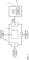
- Fig. 1 shows a schematic representation of a control unit 100 which is configured for executing the method for determining a dynamic laser beam shape for laser cutting by means of a laser cutting machine L.
- the laser machine L has a cutting head CH, which may comprise at least one optical module.
- the optical module may be implemented as a dynamic laser beam shaping module DBSM or as another type of optical module for varying the shape of the laser beam dynamically.
- the laser is equipped with the controller PLC.
- the control unit 100 may be provided as separate entity being in data exchange with the laser cutting machine L and in particular with the controller PLC of the same. Alternatively, or in addition, the control unit 100 may be implemented directly on the controller PLC of the laser cutting machine L.
- the control unit 100 comprises a cutting plan interface 101 which is configured for receiving a cutting plan to be processed on the laser cutting machine L for cutting out parts of a workpiece.
- Each part is defined by a cutting contour according to the cutting plan.
- the cutting contour itself is segmented or subdivided in a set of different types of cutting segments, for example a straight-line segment, a curve segment with the first radius and another curve segment with a second radius, a corner segment a lead-in the segment etc.
- the part shares the properties of the workpiece (before cutting, the part and the workpiece are not separated).
- the workpiece has properties.
- the workpiece is made of a certain type of material and has a certain type of thickness. Also, further properties may be processed.
- the properties are encoded by a property indicator.
- the type of material is encoded in the material indicator and/or the thickness is encoded in a thickness indicator.
- the control unit 100 further comprises an interface 102, interfacing with the shape storage ShS.
- the shape storage ShS is configured for storing a set of different dynamic laser beam shapes, in particular more than two such different dynamic laser beam shapes.
- the control unit 100 further comprises a processor P which is configured for automatically calculating for each of the cutting segments iteratively for all parts to be cut out of the workpiece an allocation to the particular dynamic laser beam shape of the set of dynamic laser beam shapes, stored in the shape storage ShS. Calculating the allocation is based on the property indicator of the related workpiece.
- the property indicator(s) may be derived from the cutting plan. Automatically calculating the allocation "type of cutting segment - selected dynamic laser beam shape" is executed specifically for each type of cutting segment.
- a first type of cutting segment (e.g., a straight-line segment) is allocated to a first dynamic laser beam shape and a second type of cutting segment (e.g., a corner segment) is allocated to a second dynamic laser beam shape and third type of cutting segment (e.g., a lead-in segment) is allocated again to the first dynamic laser beam shape and so on and so forth.
- the relation between the type of segment and the type of dynamic laser beam shape may be an n:m-relation.
- the allocation may be provided by executing an allocation algorithm.
- the allocation algorithm may access a rule database R-DB.
- the rule database is configured for storing rules for determining the relation between segment type and type of dynamic laser beam shape.
- the allocation algorithm may apply machine learning algorithm and/or a neural network.
- the processor P is configured for providing control instructions CI on an output interface 103, which connects the control unit 100 with the laser cutting machine L.
- the provided control instructions CI are configured for controlling the laser cutting machine L for executing the received cutting plan by applying the determined dynamic laser beam shapes for each cutting segment or each type of cutting segment specifically.
- the laser cutting machine is configured for processing /cutting materials and thicknesses for example as follows:
- Material properties may comprise:
- Fig. 2 shows a module or a method, respectively for training the allocation algorithm.
- the training is executed on a processing entity, which may be different from the processor and/or the control unit.
- the processing entity on which the training is executed on is a separate unit.
- the processing entity comprises an input interface 21, which is configured for receiving a tuple, consisting of a particular dynamic laser beam shape i (represented by its indicators, like e.g., oscillation frequencies in various directions) and a particular type of segment a. Both, the dynamic laser beam shape and the type of segment are provided as result dataset of the allocation algorithm. With other words, the allocation algorithm has matched the dynamic laser beam shape i to the type of segment a.
- the result of the allocation algorithm is forwarded via the output interface 23 to the processing entity.
- an assessment of the cutting result is executed.
- the assessment may e.g., be a quality assessment.
- the assessment is encoded in an assessment dataset.
- the assessment dataset is provided to the processing entity by means of the input interface 22.
- the processing entity is configured for evaluating the assessment dataset and optionally for comparing it with reference assessment datasets for providing an assessment of the allocation by means of output interface 23.
- the assessment of the allocation relates to the received particular dynamic laser beam shape i and the received particular segment a.
- a training data set and/or weights may be fed back to the allocation algorithm in order to calibrate and/or train the same.
- allocations between dynamic laser beam shapes and segment types will be rewarded if they have a positive assessment of the allocation and otherwise will be penalized if they have a negative assessment of the allocation.
- Fig. 3 is a flow chart of a method for determining a segment-specific dynamic laser beam shape for laser cutting contour according to a cutting plan according to a preferred embodiment of the present invention.
- a cutting plan is received.
- the cutting plan encodes contours of parts which are to be cut out of a workpiece.
- the cutting plan further includes workpiece properties, indicating the type of material and/or the thickness of the material.
- the properties of the workpiece are identical to the properties of the parts to be cut out of the workpiece.
- step S2 the shape storage ShS is accessed with the cutting segment of the set of cutting segments, received with the cutting plan in the preceding step.
- a set of dynamic laser beam shapes is stored, particularly more than two and preferably an amount of dynamic laser beam shapes.
- frequency and/or amplitude in X/Y/Z direction can in principle be selected arbitrarily within the adjustment ranges. The amount may be above 3 at minimum for pierce-in, Curve segment, Straight-Line segment and until several hundred or a thousand dynamic laser beam shapes and in particular, in the range between 3 and 100.
- Step S3 relates to automatically calculating for each of the cutting segments iteratively for all parts to be cut out of the workpiece an allocation to a dynamic laser beam shape of the set of dynamic laser beam shapes, accessed in the shape storage ShS. Calculating the allocation, S3, is based on the property indicator of the workpiece. Calculating the allocation is specific for the respective type of cutting segment.
- Step S4 relates to providing control instructions CI for controlling the laser cutting machine L for executing the received cutting plan by applying the determined dynamic laser beam shapes for each cutting segment specifically. After this, the method may be reiterated or may end.
- Fig. 4 is an example of a cutting contour with different types of segments.
- the cutting contour comprises a part of a circle element with one circle cut-out and a small circle cutting segment above the cut-out and in the upper right portion of the circle cutting contour.
- the transition segments are depicted in figure 4 by a left hatched pattern.
- Reference numeral 81a (on the right-hand side of Fig. 4 ) depicts a "pierce in” cutting segment for the outer circle cutting contour.
- Reference numeral 81a2 represents the dynamic laser beam shaping transition zone from segment 81 a to segment 82a.
- the latter segment 82a represents a "lead in straight” cutting segment.
- Reference numeral 82a3 depicts that dynamic laser beam shaping transition zone between segment 82a to segment 83.
- the latter segment 83 represents “straight-line” cutting segment, there the laser cutting head may be moved quicker compared to corner segments.
- Reference numeral 834 represents the dynamic laser beam shaping transition zone or phase between segment 83 and segment 84.
- the segment 84 is "right turn corner” cutting segment.
- Reference numeral 845 represents the dynamic laser beam shaping transition zone or phase between segment 84 and segment 85. Segment 85 refers to another straight-line cutting segment. Reference numeral 856 represents a dynamic laser beam shaping transition zone or phase between segment 85 and segment 86. Segment 86 represents a "left turn corner" cutting segment.
- the contour further comprises another circle cutting segment, represented in figure 4 by reference numeral 87.
- This circle contour has a "pierce in” cutting segment, represented in figure 4 with reference 81b.
- the dynamic laser beam shaping transition zone between segment 81b and segment 82b is represented in figure 4 with the reference numeral 81b2b.
- Fig. 5 is another example of a cutting contour with different types of segments.
- the contour comprises a straight-line segment 51. Proceeding in a clock-wise manner, the next segment in the contour is segment 52, which is a corner segment. Then, segment 53 is again another straight-line segment, followed by corner segment 54, followed by another corner segment 55, having another radius.
- Segment 56 is a straight-line segment, followed by a sequence of corner or radii segments, which are represented in Fig. 5 with reference numeral 56-1, 56-2, 56-3 and 56-4. As can be seen in the Figure, the radii are varying between the different 56-segments.
- a segment 57 is provided, followed by different radii segments 58, 59, followed again by a straight-line segment 60. Subsequently, the laser cutting head H has to move on to corner segment 61 for closing the closed contour structure again.
Landscapes
- Engineering & Computer Science (AREA)
- Physics & Mathematics (AREA)
- Optics & Photonics (AREA)
- Mechanical Engineering (AREA)
- Plasma & Fusion (AREA)
- Artificial Intelligence (AREA)
- Evolutionary Computation (AREA)
- Laser Beam Processing (AREA)
Priority Applications (6)
| Application Number | Priority Date | Filing Date | Title |
|---|---|---|---|
| EP21204460.6A EP4169653A1 (fr) | 2021-10-25 | 2021-10-25 | Détermination automatique d'une forme de faisceau laser dynamique pour une machine de découpe laser |
| PCT/EP2022/079623 WO2023072846A1 (fr) | 2021-10-25 | 2022-10-24 | Détermination automatique d'une forme de faisceau laser dynamique pour une machine de découpe laser |
| CN202280071150.4A CN118159383B (zh) | 2021-10-25 | 2022-10-24 | 用于确定动态激光束形状的计算机实现方法、控制单元、计算机程序产品以及计算机可读存储介质 |
| US18/701,048 US12269114B2 (en) | 2021-10-25 | 2022-10-24 | Automatic determination of a dynamic laser beam shape for a laser cutting machine |
| JP2024522651A JP7638449B2 (ja) | 2021-10-25 | 2022-10-24 | レーザ切断機のための動的レーザビーム形状の自動決定 |
| EP22809374.6A EP4392200B1 (fr) | 2021-10-25 | 2022-10-24 | Détermination automatique d'une forme de faisceau laser dynamique pour une machine de découpe laser |
Applications Claiming Priority (1)
| Application Number | Priority Date | Filing Date | Title |
|---|---|---|---|
| EP21204460.6A EP4169653A1 (fr) | 2021-10-25 | 2021-10-25 | Détermination automatique d'une forme de faisceau laser dynamique pour une machine de découpe laser |
Publications (1)
| Publication Number | Publication Date |
|---|---|
| EP4169653A1 true EP4169653A1 (fr) | 2023-04-26 |
Family
ID=78617143
Family Applications (2)
| Application Number | Title | Priority Date | Filing Date |
|---|---|---|---|
| EP21204460.6A Withdrawn EP4169653A1 (fr) | 2021-10-25 | 2021-10-25 | Détermination automatique d'une forme de faisceau laser dynamique pour une machine de découpe laser |
| EP22809374.6A Active EP4392200B1 (fr) | 2021-10-25 | 2022-10-24 | Détermination automatique d'une forme de faisceau laser dynamique pour une machine de découpe laser |
Family Applications After (1)
| Application Number | Title | Priority Date | Filing Date |
|---|---|---|---|
| EP22809374.6A Active EP4392200B1 (fr) | 2021-10-25 | 2022-10-24 | Détermination automatique d'une forme de faisceau laser dynamique pour une machine de découpe laser |
Country Status (5)
| Country | Link |
|---|---|
| US (1) | US12269114B2 (fr) |
| EP (2) | EP4169653A1 (fr) |
| JP (1) | JP7638449B2 (fr) |
| CN (1) | CN118159383B (fr) |
| WO (1) | WO2023072846A1 (fr) |
Cited By (1)
| Publication number | Priority date | Publication date | Assignee | Title |
|---|---|---|---|---|
| CN120055579A (zh) * | 2025-04-23 | 2025-05-30 | 宿迁力士乐智能装备有限公司 | 一种实现数字化高精度控制的激光切割机 |
Families Citing this family (5)
| Publication number | Priority date | Publication date | Assignee | Title |
|---|---|---|---|---|
| CN118305474B (zh) * | 2024-04-26 | 2024-09-27 | 北京允升吉电子有限公司 | 金属微孔模板振镜激光切割质量优化控制方法及系统 |
| CN119159250B (zh) * | 2024-10-21 | 2025-04-25 | 南通西塔自动化科技有限公司 | 用于复杂形状切割的激光切割系统 |
| CN119689975B (zh) * | 2024-12-31 | 2025-09-09 | 昆山冠业达精密工业有限公司 | 用于异形零件的数控切割路径优化方法及系统 |
| CN119733971B (zh) * | 2025-03-04 | 2025-05-30 | 深圳旭伟兴精密设备有限公司 | 一种基于激光切割设备的节能控制方法及装置 |
| CN120370845B (zh) * | 2025-04-21 | 2025-10-17 | 江苏觅科激光设备有限公司 | 激光切割机光束稳定与传输优化方法及平台 |
Citations (1)
| Publication number | Priority date | Publication date | Assignee | Title |
|---|---|---|---|---|
| WO2019145536A1 (fr) | 2018-01-29 | 2019-08-01 | Bystronic Laser Ag | Dispositif optique de mise en forme d'un faisceau d'ondes électromagnétiques et son utilisation, dispositif de traitement de faisceau et son utilisation, et procédé de traitement de faisceau |
Family Cites Families (20)
| Publication number | Priority date | Publication date | Assignee | Title |
|---|---|---|---|---|
| US5004890A (en) * | 1990-02-20 | 1991-04-02 | Amada Company, Limited | Method of evaluating quality of a laser beam in a laser processing machine |
| DE4404141A1 (de) * | 1994-02-09 | 1995-08-10 | Fraunhofer Ges Forschung | Vorrichtung und Verfahren zur Laserstrahlformung, insbesondere bei der Laserstrahl-Oberflächenbearbeitung |
| US5856649A (en) * | 1994-02-25 | 1999-01-05 | Fanuc Ltd. | Laser beam machine |
| US8497450B2 (en) * | 2001-02-16 | 2013-07-30 | Electro Scientific Industries, Inc. | On-the fly laser beam path dithering for enhancing throughput |
| US7173212B1 (en) * | 2004-02-13 | 2007-02-06 | Semak Vladimir V | Method and apparatus for laser cutting and drilling of semiconductor materials and glass |
| US8198564B2 (en) * | 2008-09-09 | 2012-06-12 | Electro Scientific Industries, Inc. | Adaptive optic beamshaping in laser processing systems |
| JP2012115899A (ja) | 2010-11-09 | 2012-06-21 | Amada Co Ltd | レーザ切断加工方法及びレーザ加工装置 |
| JP5255137B2 (ja) | 2011-10-07 | 2013-08-07 | ファナック株式会社 | 加工経路におけるコーナ部を加工する制御装置 |
| US10005154B2 (en) * | 2012-02-14 | 2018-06-26 | Murata Machinery, Ltd. | Laser processing machine |
| JP6071641B2 (ja) * | 2013-02-27 | 2017-02-01 | 三菱重工業株式会社 | 加工装置、加工方法 |
| WO2014133013A1 (fr) * | 2013-02-27 | 2014-09-04 | コマツ産機株式会社 | Procédé pour commander la production d'une machine de traitement au laser à fibre et machine de traitement au laser à fibre |
| JP6025652B2 (ja) * | 2013-05-15 | 2016-11-16 | 株式会社アマダホールディングス | レーザ加工方法及びレーザ加工プログラム作成装置 |
| US9446472B2 (en) * | 2014-03-05 | 2016-09-20 | Lincoln Global, Inc. | System and method for integrated controller |
| JP6116757B2 (ja) | 2014-04-10 | 2017-04-19 | 三菱電機株式会社 | レーザ加工装置 |
| US10239155B1 (en) * | 2014-04-30 | 2019-03-26 | The Boeing Company | Multiple laser beam processing |
| DE102016111455B4 (de) * | 2016-06-22 | 2019-07-25 | Trumpf Laser- Und Systemtechnik Gmbh | Verfahren zur Bestimmung einer Referenz-Fokuslage sowie Werkzeugmaschine |
| EP3404396B1 (fr) * | 2017-05-17 | 2019-12-18 | Roche Diagnostics GmbH | Système de traitement d'un substrat d'échantillon de fluide séché et procédé associé |
| JP6795567B2 (ja) * | 2018-10-30 | 2020-12-02 | ファナック株式会社 | 加工条件設定装置及び三次元レーザ加工システム |
| EP3671373A1 (fr) * | 2018-12-19 | 2020-06-24 | Bystronic Laser AG | Méthode de prédiction pour prédire le résultat de l'usinage pour une méthode d'usinage à laser |
| JP6923585B2 (ja) * | 2019-03-18 | 2021-08-18 | ファナック株式会社 | 機械学習装置、制御装置、レーザ加工機、及び機械学習方法 |
-
2021
- 2021-10-25 EP EP21204460.6A patent/EP4169653A1/fr not_active Withdrawn
-
2022
- 2022-10-24 JP JP2024522651A patent/JP7638449B2/ja active Active
- 2022-10-24 EP EP22809374.6A patent/EP4392200B1/fr active Active
- 2022-10-24 CN CN202280071150.4A patent/CN118159383B/zh active Active
- 2022-10-24 US US18/701,048 patent/US12269114B2/en active Active
- 2022-10-24 WO PCT/EP2022/079623 patent/WO2023072846A1/fr not_active Ceased
Patent Citations (1)
| Publication number | Priority date | Publication date | Assignee | Title |
|---|---|---|---|---|
| WO2019145536A1 (fr) | 2018-01-29 | 2019-08-01 | Bystronic Laser Ag | Dispositif optique de mise en forme d'un faisceau d'ondes électromagnétiques et son utilisation, dispositif de traitement de faisceau et son utilisation, et procédé de traitement de faisceau |
Non-Patent Citations (3)
| Title |
|---|
| CINDY GOPPOLDTHOMAS PINDERPATRICK HERWIG: "Dynamic beam shaping for thick sheet metal cutting", LASERS IN MANUFACTURING CONFERENCE, 2017 |
| SHEKEL, EYAL: "Advanced Laser Welding With Dynamic Beam", 8 July 2020 (2020-07-08), XP055907514, Retrieved from the Internet <URL:https://www.youtube.com/watch?v=LDClb_aNEnI> * |
| SHEKEL, EYAL: "Beam Shaping in lasers for material processing Webinar", 22 March 2021 (2021-03-22), XP055907533, Retrieved from the Internet <URL:https://www.youtube.com/watch?v=SN3qk58P310> * |
Cited By (1)
| Publication number | Priority date | Publication date | Assignee | Title |
|---|---|---|---|---|
| CN120055579A (zh) * | 2025-04-23 | 2025-05-30 | 宿迁力士乐智能装备有限公司 | 一种实现数字化高精度控制的激光切割机 |
Also Published As
| Publication number | Publication date |
|---|---|
| EP4392200A1 (fr) | 2024-07-03 |
| JP7638449B2 (ja) | 2025-03-03 |
| EP4392200B1 (fr) | 2024-11-20 |
| CN118159383B (zh) | 2025-05-27 |
| US12269114B2 (en) | 2025-04-08 |
| WO2023072846A9 (fr) | 2024-03-28 |
| WO2023072846A1 (fr) | 2023-05-04 |
| CN118159383A (zh) | 2024-06-07 |
| US20240326160A1 (en) | 2024-10-03 |
| JP2024539040A (ja) | 2024-10-28 |
Similar Documents
| Publication | Publication Date | Title |
|---|---|---|
| EP4392200B1 (fr) | Détermination automatique d'une forme de faisceau laser dynamique pour une machine de découpe laser | |
| US10780577B2 (en) | Machine learning device, robot system, and machine learning method for learning operations of robot and laser scanner | |
| Knaak et al. | Improving build quality in laser powder bed fusion using high dynamic range imaging and model-based reinforcement learning | |
| Cao et al. | A machine learning method to quantitatively predict alpha phase morphology in additively manufactured Ti-6Al-4V | |
| US10884396B2 (en) | Sensor based smart segmentation | |
| CN115775249B (zh) | 一种增材制造造件成形质量监测方法、系统及存储介质 | |
| Garcia-Moreno et al. | Ex-situ porosity classification in metallic components by laser metal deposition: A machine learning-based approach | |
| Moradi et al. | Intelligent laser-based metal additive manufacturing: A review on machine learning for process optimization and property prediction | |
| CN114406502A (zh) | 激光金属切割方法及系统 | |
| US11954413B2 (en) | Evaluating candidate virtual build volumes | |
| Tatzel et al. | Image-based modelling and visualisation of the relationship between laser-cut edge and process parameters | |
| WO2023205431A1 (fr) | Prédiction de distorsion pour fabrication additive à l'aide d'une analyse d'image | |
| Pan et al. | Predictive analysis and feature extraction of weld penetration in P-GMAW based on interpretable deep learning | |
| EP4422820B1 (fr) | Détermination des phases de transition pour la transformation de différentes formes dynamiques de faisceau laser pour une machine de découpe laser | |
| CN119347794B (zh) | 一种坡口路径与焊接速度规划方法和系统 | |
| Nguyen et al. | Optimizing selective laser melting 3D printing lines with convolutional neural networks model | |
| Memari et al. | Correlation between Process Parameters and Defects in Additively Manufactured Components Using Image Processing and Machine Learning | |
| CN121467963A (zh) | 工艺优化方法、系统、电子设备及存储介质 | |
| Jiang | Analysis of laser melting and resolidification related to additive manufacturing | |
| Gawade | Integration of Physics With Data Science Models for Predicting Porosity and Emission in Additive Manufacturing | |
| Alves | Computer Vision for Laser Metal Deposition (LMD) | |
| US20220291661A1 (en) | Additive manufacturing simulations | |
| Mubarak et al. | Classification of microscopic aluminium inclusions using machine learning techniques and generative methods | |
| Broderick | Defect Detection Automation for Metal Additive Manufacturing With Deep Learning | |
| CN120962175A (zh) | 一种用于板件加工的激光切孔系统 |
Legal Events
| Date | Code | Title | Description |
|---|---|---|---|
| PUAI | Public reference made under article 153(3) epc to a published international application that has entered the european phase |
Free format text: ORIGINAL CODE: 0009012 |
|
| STAA | Information on the status of an ep patent application or granted ep patent |
Free format text: STATUS: THE APPLICATION HAS BEEN PUBLISHED |
|
| AK | Designated contracting states |
Kind code of ref document: A1 Designated state(s): AL AT BE BG CH CY CZ DE DK EE ES FI FR GB GR HR HU IE IS IT LI LT LU LV MC MK MT NL NO PL PT RO RS SE SI SK SM TR |
|
| STAA | Information on the status of an ep patent application or granted ep patent |
Free format text: STATUS: THE APPLICATION IS DEEMED TO BE WITHDRAWN |
|
| 18D | Application deemed to be withdrawn |
Effective date: 20231027 |