EP4169654A1 - Bestimmung von übergangsphasen zur transformation unterschiedlicher dynamischer laserstrahlformen für eine laserschneidmaschine - Google Patents
Bestimmung von übergangsphasen zur transformation unterschiedlicher dynamischer laserstrahlformen für eine laserschneidmaschine Download PDFInfo
- Publication number
- EP4169654A1 EP4169654A1 EP21204469.7A EP21204469A EP4169654A1 EP 4169654 A1 EP4169654 A1 EP 4169654A1 EP 21204469 A EP21204469 A EP 21204469A EP 4169654 A1 EP4169654 A1 EP 4169654A1
- Authority
- EP
- European Patent Office
- Prior art keywords
- laser beam
- cutting
- dynamic laser
- specific dynamic
- transition
- Prior art date
- Legal status (The legal status is an assumption and is not a legal conclusion. Google has not performed a legal analysis and makes no representation as to the accuracy of the status listed.)
- Withdrawn
Links
Images




Classifications
-
- B—PERFORMING OPERATIONS; TRANSPORTING
- B23—MACHINE TOOLS; METAL-WORKING NOT OTHERWISE PROVIDED FOR
- B23K—SOLDERING OR UNSOLDERING; WELDING; CLADDING OR PLATING BY SOLDERING OR WELDING; CUTTING BY APPLYING HEAT LOCALLY, e.g. FLAME CUTTING; WORKING BY LASER BEAM
- B23K26/00—Working by laser beam, e.g. welding, cutting or boring
- B23K26/02—Positioning or observing the workpiece, e.g. with respect to the point of impact; Aligning, aiming or focusing the laser beam
- B23K26/06—Shaping the laser beam, e.g. by masks or multi-focusing
- B23K26/064—Shaping the laser beam, e.g. by masks or multi-focusing by means of optical elements, e.g. lenses, mirrors or prisms
-
- B—PERFORMING OPERATIONS; TRANSPORTING
- B23—MACHINE TOOLS; METAL-WORKING NOT OTHERWISE PROVIDED FOR
- B23K—SOLDERING OR UNSOLDERING; WELDING; CLADDING OR PLATING BY SOLDERING OR WELDING; CUTTING BY APPLYING HEAT LOCALLY, e.g. FLAME CUTTING; WORKING BY LASER BEAM
- B23K26/00—Working by laser beam, e.g. welding, cutting or boring
- B23K26/02—Positioning or observing the workpiece, e.g. with respect to the point of impact; Aligning, aiming or focusing the laser beam
- B23K26/06—Shaping the laser beam, e.g. by masks or multi-focusing
- B23K26/073—Shaping the laser spot
-
- B—PERFORMING OPERATIONS; TRANSPORTING
- B23—MACHINE TOOLS; METAL-WORKING NOT OTHERWISE PROVIDED FOR
- B23K—SOLDERING OR UNSOLDERING; WELDING; CLADDING OR PLATING BY SOLDERING OR WELDING; CUTTING BY APPLYING HEAT LOCALLY, e.g. FLAME CUTTING; WORKING BY LASER BEAM
- B23K26/00—Working by laser beam, e.g. welding, cutting or boring
- B23K26/36—Removing material
- B23K26/38—Removing material by boring or cutting
-
- G—PHYSICS
- G05—CONTROLLING; REGULATING
- G05B—CONTROL OR REGULATING SYSTEMS IN GENERAL; FUNCTIONAL ELEMENTS OF SUCH SYSTEMS; MONITORING OR TESTING ARRANGEMENTS FOR SUCH SYSTEMS OR ELEMENTS
- G05B19/00—Program-control systems
- G05B19/02—Program-control systems electric
- G05B19/18—Numerical control [NC], i.e. automatically operating machines, in particular machine tools, e.g. in a manufacturing environment, so as to execute positioning, movement or co-ordinated operations by means of program data in numerical form
- G05B19/4097—Numerical control [NC], i.e. automatically operating machines, in particular machine tools, e.g. in a manufacturing environment, so as to execute positioning, movement or co-ordinated operations by means of program data in numerical form characterised by using design data to control NC machines, e.g. CAD/CAM
-
- G—PHYSICS
- G05—CONTROLLING; REGULATING
- G05B—CONTROL OR REGULATING SYSTEMS IN GENERAL; FUNCTIONAL ELEMENTS OF SUCH SYSTEMS; MONITORING OR TESTING ARRANGEMENTS FOR SUCH SYSTEMS OR ELEMENTS
- G05B2219/00—Program-control systems
- G05B2219/30—Nc systems
- G05B2219/36—Nc in input of data, input key till input tape
- G05B2219/36199—Laser cutting
-
- G—PHYSICS
- G05—CONTROLLING; REGULATING
- G05B—CONTROL OR REGULATING SYSTEMS IN GENERAL; FUNCTIONAL ELEMENTS OF SUCH SYSTEMS; MONITORING OR TESTING ARRANGEMENTS FOR SUCH SYSTEMS OR ELEMENTS
- G05B2219/00—Program-control systems
- G05B2219/30—Nc systems
- G05B2219/45—Nc applications
- G05B2219/45041—Laser cutting
-
- G—PHYSICS
- G05—CONTROLLING; REGULATING
- G05B—CONTROL OR REGULATING SYSTEMS IN GENERAL; FUNCTIONAL ELEMENTS OF SUCH SYSTEMS; MONITORING OR TESTING ARRANGEMENTS FOR SUCH SYSTEMS OR ELEMENTS
- G05B2219/00—Program-control systems
- G05B2219/30—Nc systems
- G05B2219/49—Nc machine tool, till multiple
- G05B2219/49353—Control of output power of tool, laser beam
-
- G—PHYSICS
- G05—CONTROLLING; REGULATING
- G05B—CONTROL OR REGULATING SYSTEMS IN GENERAL; FUNCTIONAL ELEMENTS OF SUCH SYSTEMS; MONITORING OR TESTING ARRANGEMENTS FOR SUCH SYSTEMS OR ELEMENTS
- G05B2219/00—Program-control systems
- G05B2219/30—Nc systems
- G05B2219/49—Nc machine tool, till multiple
- G05B2219/49371—Variable laser spot width, small for boundary, large for rest
Definitions
- the present invention relates to laser cutting by means of a laser cutting machine, which is provided with at least one optical module, e.g., a dynamic laser beam shaping module, for dynamically varying the shape of the laser beam.
- a laser cutting machine which is provided with at least one optical module, e.g., a dynamic laser beam shaping module, for dynamically varying the shape of the laser beam.
- the present invention refers to a method for determining transition phases for transforming different dynamic laser beam shapes during laser cutting, a control unit and a computer program.
- a laser cutting process may be optimized for contrary demands, like inter alia productivity and quality.
- Key factor for cutting is transforming absorbed laser energy into heat, to melt material. The energy coupling is determined by many factors and interacts with cut kerf conditions for instance.
- the laser cutting machine is equipped with a dynamic laser beam shaping module.
- a dynamic laser beam shaping module For applying a DBS, the laser cutting machine is equipped with a dynamic laser beam shaping module.
- An example embodiment with such a DBS application is described in WO 2019 145 536 A1 .
- the present invention relates to a computer-implemented method for determining transition phases for transforming different dynamic laser beam shapes for laser cutting by means of a laser cutting machine.
- the laser cutting machine comprises at least one optical module, which may e.g. be implemented as a dynamic laser beam shaping module, for dynamically varying the shape of the laser beam.
- the method may comprise the method steps of:
- contour errors are further minimized and cutting quality is enhanced as there will be no hard switch from one dynamic laser beam shape to a directly following or consecutive one.
- the transition between different dynamic laser beam shapes is smoothed and improved.
- Enhanced cutting quality thereby includes an enhanced smoothness of the cutting edge, a minimization of burr (adhesion of melt adjacent to the cutting edge), minimization of expelled melt particles and a minimization of the risk of tear-off of the laser beam during cutting.
- the laser cutting machine may comprise more than one optical model, which assist in or cause varying the laser beam dynamically.
- two (2) galvo scanner mirrors one for movement in X and one in Y may be used.
- 3D beam shaping may be achieved by means of a 2-axis module for X/Y variation and a Z-wobbling module for movement in the direction of the beam axis.
- a CIVAN laser system may be used for shaping the beam by interconnection of e.g., 32 single optical modules.
- the cutting segments are selected from the group, comprising:
- the allocation tool and/or the transition tool may comprise or may access a trained model, in particular a neural network model.
- the neural network may be, for example, a convolutional neural network (CNN).
- CNN convolutional neural network
- the neural network has been trained to determine a transition phase for transforming a dynamic laser beam shape between two consecutive cutting segments. For instance, for segment i and segment i+1 the neural network or machine learning model is trained to provide a transition phase for transforming the dynamic laser beam between segment i and segment i+1.
- the trained neural network model may be stored e.g., on a cloud-based sever, which is in data exchange with the control unit.
- the (deep) machine learning algorithms are data and computation intensive and are therefore preferably computed on a graphics processing unit (GPU) or a tensor processing unit (TPU) or networks of processors.
- GPU graphics processing unit
- TPU tensor processing unit
- Each layer of the neural network can be computed on powerful massively parallelizable processors, especially multi-core or many-core processors.
- the computing unit is preferably designed as or comprises a graphics card or the other hardware modules mentioned above.
- the machine learning model is trained to recognize transition phases without a preceding analysis of properties (or features - feature extraction), which properties/features, in particular which spatial and/or temporal properties, of the first and second cutting segment are relevant for the determination of the transition phase.
- This approach thus implements a featureextractor-free (or feature-free) process. This means that a so-called end-to-end algorithm can be implemented.
- End-to-end in this context means that the raw data, i.e., the acquired transition phases, can be used without substantial preprocessing and, in particular, without manual determination of the features in the cutting segments and its processing, which are subsequently further processed (e.g., classified) to a result using a machine learning algorithm (also referred to as ML algorithm for short in the following).
- machine learning algorithm also referred to as ML algorithm for short in the following.
- Without significant preprocessing in this context means apart from marginal preprocessing, such as histogram equalization, image depth reduction and/or region of interest (ROI) cropping.
- the end-to-end approach does not require separate preprocessing of the raw data to extract the 'features' that are important for learning.
- the essential information is often also contained in very complex, superimposed or hardly graspable signal, image or representation of the cutting sequence features, which makes an optimal feature analysis difficult. Therefore, it is not surprising that the deep learning approach implemented here is superior to feature extractor-based approaches without any feature extraction.
- the neural network may have been trained with a training algorithm based on annotated or partially annotated training data, which comprise an assessment of the cutting result with the applied transition phase.
- the training algorithm may be a supervised learning method or a semi-supervised learning method.
- the training algorithm may be based on historical data.
- Reinforcement learning methods can also be used to update or adapt the models. Reinforcement learning makes it possible to find solutions to this complex problem without initial data and (prior) knowledge about the laser cutting process and the transition phases. In addition, reinforcement learning eliminates the need for time-consuming collection and processing of training data.
- GRU gated recurrent units
- LSTM long short-term memory networks
- the transition tool comprises an assessment tool, wherein the assessment tool is configured for assessing the determined and applied specific dynamic laser beam shapes and/or transition phases manually by means of using a user interface and/or automatically by a sensory automatic assessment unit for providing an assessment dataset.
- the sensory automatic assessment unit may comprise an in process optical system, in particular a camera and/or a set of diodes. Also, both may be combined, so that both modes (automatic and manual mode) may be used as verification step, which may be provided as a semi-automatic mode. So, for example, first the sensory automatic assessment unit may provide a first assessment dataset automatically, which may be subject to a verification step by manual input (via a human machine interface). Based on the manual input, a second assessment dataset is generated. The second assessment dataset may be compared with the first one and in case of deviations being higher than a preconfigured threshold, a warning message may be generated, indicating that the assessment may be subject to further evaluation and/or verification.
- the assessment dataset comprises setting a configurable share of different assessment criteria in common, comprising a quality assessment, a performance assessment, an energy consumption assessment, and/or a process stability assessment, wherein the different assessment criteria have interdependencies which are modelled on a user interface selection button, provided on a human machine interface.
- the user interface selection button is configured such that inconsistent input is not possible anymore. So, e.g., if a user would like to input a highest ranking for quality and in addition a highest ranking for performance and in addition also a lowest ranking of energy consumption, this would be evaluated as inconsistent and denied as admissible input.
- the user is requested to input corrected values.
- the transition phases for each two consecutive specific dynamic laser beam shapes are determined specifically for a type of material property and/or a type of cutting machine.
- the type of material property may comprise a material type (type of material, like steel, alloy, aluminum etc.) and/or material thickness (e.g., for flat material with a thickness in between 0.1 mm to 100 mm).
- the transition phases for each two consecutive specific dynamic laser beam shapes are determined in dependence of a speed and/or acceleration and/or jerk of the laser cutting head and/or of a type of cutting segment and/or of laser cutting process parameters, including laser power and/or dynamic limits of drives.
- the transition phase is determined by generating focal point oscillation schemes by spatiotemporal distribution of laser energy over a focal plane and/or a material surface with respect to:
- a transfer function f is applied which transfers the first specific dynamic laser beam shape of the two consecutive specific dynamic laser beam shapes in the second specific dynamic laser beam shape, wherein the transfer function f transforms a frequency, an amplitude and/or a phase shift of the first dynamic laser beam shape.
- the transfer function f may be linear, higher order exponential, trigonometric, or logarithmic.
- the transition tool for determining the transition phases between each two consecutive specific dynamic laser beam shapes is configured for determining a transition phase between each two consecutive specific dynamic laser beam shapes, which differ from each other.
- a first cutting segment differs from the consecutive second cutting segment per definition.
- the first cutting segment may be a straight-line segment and the second segment may be a corner segment with a curve.
- the first cutting segment differs from the second one.
- the queue of cutting segments may be defined differently, so that a first cutting segment may be of a first type and the second cutting segment may be of the same (first) type.
- the transition tool does not need to be accessed so that no transition phase will be calculated between two identical or similar consecutive cutting segments, in order to reduce computing resource consumption.
- the definition of cutting segments may be configured in a preceding configuration phase, by means of user input.
- the similarity of the cutting segments may be defined according to a predefined scheme. For example, a straight-line segment, followed by another straight-line segment, in a slightly different angle may be judged to be similar. Threshold values may be defined in a preparation phase of the method.
- control unit for providing control instructions for controlling a laser cutting machine by determining transition phases for transforming different dynamic laser beam shapes for the laser cutting machine, comprising at least one optical module, which in a preferred embodiment may be implemented as a dynamic laser beam shaping module, for dynamically varying the shape of the laser beam.
- the control unit is configured for executing the method as described above.
- the control unit may comprise:
- the invention in another aspect relates to a computer program comprising a computer program code, the computer program code when executed by a processor causing the processor to perform the steps of the method as described above.
- the invention relates to a computer readable storage medium in which computer program as described above is stored.
- the at least one optical module is configured for assisting in and/or causing a variation of the laser beam dynamically.
- the at least one optical module may comprise a dynamic laser beam shaping module.
- the dynamic laser beam shaping module is configured for dynamically change the shape of the laser beam during cutting a contour according to the cutting plan.
- the dynamic laser beam shaping module may apply a wobbling and/or a dynamic laser beam shaping.
- the dynamic laser beam shaping module may be configured to use also a combination of the before mentioned options, i.e., a combination of using the variable laser beam diameter with the wobbling of the focal position and the DBS parameters (X, Y axis).
- a cutting segment typically is provided in an ordered series or queue of cutting segments.
- the cutting segments are ordered such as a first cutting segment is preceding a second one, which is preceding a third one etc.
- the cutting segments and/or the queue of cutting segments may be defined in a cutting plan or may be calculated from data within the cutting plan.
- the queue is, in particular, based on a cutting direction of the laser cutting head, moving over a surface of the workpiece to be cut.
- a cutting segment represents different types of cuts on a geometry according to the cutting plan to be executed.
- a cutting segment may be e.g., a straight line, a curve with varying radii (parameterized curve), which may represent a corner, a circle or circle segment, a pierce-in, a lead-in, a lead-out, and/or an engraving.
- a transition phase is to be construed as a special and/or temporal phase for transforming a first specific dynamic laser beam shape in a consecutive second specific dynamic laser beam shape for two consecutive cutting segments in the queue of cutting segments.
- the transition phase may be represented as a transition zone or pattern.
- the transition phase may be configured such that a smooth transformation between the respective two consecutive specific dynamic laser beam shapes is provided by defining the transition between two segments by the cutting speed.
- maximal cutting speed e.g., the horseshoe-shape is assumed to fit best the user-defined performance criteria. The slower the cutting speed, the more circular the dynamic laser beam shape is assumed to be best.
- Different phases of the transition may be provided, e.g., the dynamic laser beam shape at full speed, in the corner at zero speed and in between. Further examples, are provided in the detailed description.
- a workpiece may be a metal workpiece.
- the workpiece may be a sheet or a tube workpiece.
- the workpiece may e.g., be a metal sheet of different type and/or having different thickness.
- the cutting plan defines the parts which need to be cut out of the workpiece.
- the parts to be cut out from the workpiece may have a particular contour, which may differ from part to part. For instance, a first set of circle parts need to be cut out completely from the workpiece and a second set of rectangle parts need to be cut out.
- Each part to be cut out may be defined by a cutting contour.
- the cutting contour may consist of a set or a number of cutting segments.
- a rectangle part may comprise a first segment as a first straight-line segment, followed by second segment, being a corner segment (radius), followed by a third segment, being a second straight-line segment, followed by a fourth segment, being a corner segment, followed by a fifth segment, being a first straight-line segment again etc.
- the cutting contour defines the shape of a part from a top view.
- the queue of cutting segments is defined by the movement direction of the cutting head.
- the queue is an ordered list of cutting segments, which are cut one after the other.
- the laser cutting machine is configured for applying a laser beam on a workpiece for thermal separation of workpiece material by laser radiation.
- the workpiece may be a tube workpiece or a flat, sheet-like workpiece with a cutting length of up to 12 meters and a width of 2 to 3 meters.
- the laser cutting machine may be configured for 3D metal sheets, like tubes or bended parts.
- the laser cutting machine is equipped with at least one optical module.
- the laser cutting machine may, e.g.,comprise a dynamic laser beam shaping module which may comprise e.g., a laser scanner optics (e.g., as described in WO2019145536A1 ) or a lens-optics which is actuated or oscillated in x and y directions perpendicular to the laser beam axis (as e.g., described in WO 2019/145536 A1 ).
- the technical purpose of the dynamic laser beam shaping (module), DBSM is quality and/or performance improvement.
- the DBSM may be used to provide the energy on a bigger area on the workpiece.
- DBSM serves for providing less damage of material properties because of lower interaction time with high power laser (less heat accumulation), which is a major improvement.
- quality improvement Amongst standard cutting parameters (focal position, laser power, gas pressure, ...) using additionally dynamic laser beam shapes allows, choosing the cutting and dynamic laser beam shaping parameters accordingly, to reach better quality and/or performance with higher dimensions of parameter space.
- the dynamic beam shaping may be applied with different beam shaping frequencies.
- the beam shaping frequencies may be in the range between 100Hz and one or more Mega Hz and preferably in the range between 100Hz and 900KHz or between 100Hz and several hundred Kilo Hz.
- the beam shaping frequency may be varied in each of the above-mentioned directions, i.e., in X and Y and even in Z direction.
- the beam shaping frequencies may be set differently in each of these directions, so that e.g., in X direction a first beam shaping frequency of e.g., 200Hz may be applied and in Y direction a second beam shaping frequency of e.g., 900kHz may be used.
- the beam shaping frequency settings for each direction may be set and configured independently form each other on a user interface.
- the laser pulse frequency may be varied.
- the laser pulse frequency may be varied in between 0 and 5kHz.
- laser pulse frequency is only used for specific applications, e.g., engraving, pulsed cutting (e.g., when piercing, curves, corners) so that energy input may be regulated by pulsing.
- changing the pulse frequency of the laser beam may be used to reduce the energy to be provided on the workpiece.
- the setting of the laser pulse frequency may be configured on a human machine or user interface, HMI.
- the HMI may provide settings for configuration of the beam shaping frequency for each direction separately and in addition for configuration of the laser pulse frequency, in a combined form or in a separate manner.
- the allocation tool and/or the transition tool is/are an electronic module or may be a software module, implemented in a hardware module with a processor or may be a hardware module (as described below, e.g., FPGA; ASIC).
- a "processor” may be understood to mean, for example, a machine or an electronic circuit.
- a processor may be a central processing unit (CPU), a microprocessor or a microcontroller, for example, an application-specific integrated circuit or a digital signal processor, possibly in combination with a memory unit for storing program instructions, etc.
- a processor may also be, for example, an IC (integrated circuit), in particular an FPGA (field programmable gate array) or an ASIC (application-specific integrated circuit), or e.g., a multi-chip module, e.g., a 2.5D or 3D multi-chip module, in which in particular several so-called dies are connected to one another directly or via an interposer, or a DSP (Digital Signal Processor) or a GPU (Graphic Processing Unit).
- a processor can also be a virtualized processor, a virtual machine or a soft CPU.
- a programmable processor which is equipped with configuration steps for carrying out the said method according to the invention or is configured with configuration steps in such a way that the programmable processor implements the features according to the invention of the method, the component, the modules, or other aspects and/or partial aspects of the invention., like a FPGA or ASIC.
- the allocation tool and/or the transition tool may be part of a controller for controlling the laser cutting machine or may be a separate module, which is in data connection with the controller.
- the allocation tool may be configured for allocating a particular dynamic laser beam shape for a particular cutting segment.
- the allocation tool may be provided as table data structure with a set of entries, which may be accessed with a specific cutting segment to deduce the associated dynamic laser beam shape or vice versa.
- the step of allocating may be extended by applying a rule-based association algorithm.
- the rules for the association algorithm may be stored in a rule storage of the allocation tool and/or on another external storage, which may be accessed via a network connection by the allocation tool.
- the rules may be e.g., in the form:
- the rules may be amended independently from executing the method for determining transition phases for the dynamic laser beam shapes.
- the transition tool may be configured for defining a transition phase between two consecutive specific dynamic laser beam shapes.
- a horseshoe-shape is assumed to fit best the user-defined performance criteria. The slower the cutting speed, the more circular the dynamic laser beam shape is assumed to be best.
- Different phases of the transition may be provided, e.g., the dynamic laser beam shape at full speed, in the corner at zero speed and in between with a configurable speed.
- a transition phase is a transformation from a first specific dynamic laser beam shape to a following one.
- the transition parameters may be defined in accordance to a transfer function.
- the transfer function may be selected from a catalogue or set of functions, which may be configured in a preparation phase and which may even be amended in an operating phase of the laser machine.
- the transfer function may be selected from a database with stored transfer functions.
- the transfer function may be defined e.g., according to a transfer function catalogue.
- Optimal laser beam shapes are defined for each segment of the part.
- the transition phase between the segments is proposed to be dependent on the path speed and/or acceleration and/or jerk. Any combination of speed, acceleration and jerk dependency is possible.
- the corresponding laser beam shape may for example be represented in a Lissajous Figure.
- the amplitude A 1 and frequency a 1 are used with the time shift ⁇ 1 .
- the Y direction is given.
- the LF in the transition zone is dependent on the cutting speed LF t ( v c ) .
- Trigonometric dependencies are possible.
- the method is not limited to use only one single dependency. Alternatively, a combination of speed, acceleration and/or jerk dependent transitions are possible and might be advantageous.
- the assessment tool is an electronic module.
- the assessment tool may be a software module, implemented in a hardware module with a processor or may be a hardware module, like a FPGA or an ASIC.
- the assessment tool is configured for assessing the determined and applied specific dynamic laser beam shapes and/or transition phases manually by means of using a user interface and/or automatically by a sensory automatic assessment unit for providing an assessment dataset, which represents the assessment result.
- the invention in another aspect relates to a computer program product comprising a computer program, the computer program being loadable into a memory unit of a computing unit, including program code sections to make the computing unit execute the method for determining transition phases, as described above, when the computer program is executed in said computing unit.
- the invention in another aspect relates to a computer-readable medium, on which program code sections of a computer program are stored or saved, said program code sections being loadable into and/or executable in a computing unit to make the computing unit execute the method for determining transition phases, as described above, when the program code sections are executed in the computing unit.
- the present invention provides a tool for defining transition zones for the transformation from one dynamic laser beam shape applied in a first cutting segment to a following dynamic laser beam shape of a subsequent cutting segment in a cutting sequence.
- the cutting segments may be e.g., a "pierce in”, “straight line”, “circle”, “curvature”, “corner” etc.
- the goal of the solution described herein is to define a smooth transition from one dynamic laser beam shape (e.g., Lissajous figure or the like) to a following one, each one used on cutting segments of a cutting sequence that are following one after the other.
- one dynamic laser beam shape e.g., Lissajous figure or the like
- a possible workflow may be:
- Fig. 1 shows in a schematic representation a control unit 100 for interacting with a programmable logic control PLC for controlling a laser cutting machine L.
- the control unit 100 is configured to determine transition phases for transforming different dynamic laser beam shapes during or for laser cutting by means of the laser cutting machine L.
- the control unit 100 comprises a processor P which has implemented thereon an allocation tool 102 and a transition tool 104.
- the laser machine L has a cutting head CH that comprises at least one optical model, preferably a dynamic laser beam shaping module DBSM.
- the spatiotemporal beam oscillation may e.g., be realized by a commercial high-dynamic 2D-scanner unit which is ready for integration into the collimated beam path of the laser cutting head. Thus, optical properties are not affected.
- the scanner may consist of two oscillating mirrors where each mirror has a time-dependent position, defined by a certain frequency and amplitude. The phase shift between both mirrors is the fifth parameter to specify the energy distribution.
- Control of the dynamic laser beam shaping module DBSM is executed by means of control instructions CI, which are provided by the control unit 100.
- the control unit 100 is further configured to receive a cutting plan via a cutting plan interface 101. Based on the received cutting plan, the control unit 100 is further configured to provide control instructions CI to be forwarded to the controller PLC of the laser cutting machine L.
- the laser cutting machine L is configured for cutting workpieces according to a predefined cutting plan. For example, several parts may be cut out of a workpiece. Cutting is executed by moving the laser cutting head of the laser cutting machine L over the workpiece during application of a laser beam.
- the laser cutting machine L may be equipped with a dynamic laser beam shaping module DBSM.
- the dynamic laser beam shaping module DBSM is configured for dynamically varying the shape of the laser beam, e.g., by oscillating the laser beam in an angular direction with respect to the direction of propagation of the laser beam.
- the control unit 100 is preferably equipped with three different interfaces:
- the control unit 100 further comprises an allocation tool 102 and a transition tool 104.
- the allocation tool 102 is configured to allocate a specific dynamic laser beam shape from a (stored) set of dynamic laser beam shapes to each cutting segment in the queue of cutting segments according to pre-defined allocation criteria.
- the transition tool 104 is configured for determining the transition phase between each two consecutive specific dynamic laser beam shapes. Thus, a first specific dynamic laser beam shape of the two consecutive specific dynamic laser beam shapes is transformed into a second specific dynamic laser beam shape of the two consecutive specific dynamic laser beam shapes within a certain transition time.
- control unit 100 is provided as separate module in addition to the controller PLC of the laser cutting machine L.
- control unit 100 may be deployed on a cloud-based server, being in data exchange with the local controller PLC of the laser cutting machine L.
- FIG. 2 shows a more detailed representation of the allocation tool 102.
- the allocation tool 102 may be configured to execute an allocation algorithm in order to allocate a specific dynamic laser beam shape to each cutting segment according to pre-defined allocation criteria.
- the allocation algorithm may access a rule base with stored rules for determining the allocation under the given requirements (allocation criteria).
- allocation criteria may be based on a trained machine learning model.
- the allocation tool comprises a first interface 102-1 which is configured for receiving allocation criteria, a second interface 102-2 which is configured for receiving a digital representation of a cutting segment (one after the other in the queue of cutting segments, which are defined according to the contour to be cut according to the cutting plan) and, a third interface 102-3 which is configured to access a storage or a database DB for storing a set of dynamic laser beams shapes.
- the storage may be implemented as a database.
- the allocation tool 102 further comprises of fourth interface 102-4 for providing a result of the allocation step and in particular for providing a specific dynamic laser beam shape for a specific cutting segment.
- the allocation criteria may be defined by an allocation module and/or by manual input and/or by accessing a storage with stored allocation criteria.
- FIG. 3 shows a more detailed representation of the transition tool 104.
- the transition tool 104 comprises a first interface 104-1 for receiving a first or i-th and a respective consecutive second or i+1-th specific dynamic laser beam shape, which have been provided by the allocation tool 102.
- the transition tool 104 comprises a second interface Ul, which may be provided as a human machine interface, HMI.
- This second interface UI may serve for receiving a manual assessment data set which represents a manual assessment of the determined and applied specific dynamic laser beam shapes and/or transition phases.
- the assessment may be a quality assessment, a performance assessment, and energy consumption assessment, and/or a process stability assessment.
- the second interface UI may further serve for providing a result of an automatic assessment by means of using an automatic assessment unit, which is depicted in figure 3 with reference 104-2.
- the second interface UI may further serve for providing the calculated transition phases as an interim result for the purpose of (user-based) verification.
- the transition tool 104 further comprises another interface which serves as result interface 104-3 and which is configured for providing the determined transition phases as final result.
- the transition tool 104 may further comprise a configuration tool 104-4, which is configured for providing configuration parameters for configuring the determination of the transition zones or phases.
- the configuration tool 104-4 may be used to determine whether the determination or calculation of the transition phases should be speed-dependent and/or acceleration-dependent and/or jerk-dependent.
- the configuration tool 104-4 may be provided as a software module which generates respective entry fields on the human machine interface for specifying the assessment by means of receiving numerical input or catek-dependent.
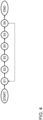
- Figure 4 shows a flowchart of an embodiment of a method for determining transition phases for transforming different dynamic laser beam shapes for laser cutting.
- a cutting plan is received.
- the allocation tool 102 is provided.
- the allocation tool 102 is accessed iteratively for determining specific dynamic laser beam shapes for each cutting segment of the queue of cutting segments.
- the transition tool 104 is provided. The transition tool 104 is configured for determining the transition phase between each two determined specific consecutive dynamic laser beams shapes, wherein the first specific dynamic laser beam shape of the two consecutive specific dynamic laser beam shapes is transformed into a second specific dynamic laser beam shape of the two consecutive specific dynamic laser beam shapes.
- step S5 the transition tool 104 is accessed for determining all transition phases between each two consecutive specific dynamic laser beam shapes.
- control instructions CI are provided for controlling the laser cutting machine L for executing the received cutting plan by applying the determined specific dynamic laser beam shape, which has been determined by the allocation tool 102 and by applying the transition phases for each of the cutting segments of all parts of the workpiece to be cut according to the cutting plan, wherein the transition phases have been determined by the transition tool 104.
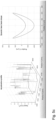
- Fig. 5a , b , and c show an acceleration dependent determination of the transition phase between each two consecutive specific dynamic laser beam shapes.
- an acceleration profile for the cutting contour according to the cutting plan is depicted.
- the position in X and Y direction is depicted and the speed is represented on the Z axis.
- the dynamic laser beam shape is depicted (here: a circle) for a position on the contour, which is represented in the acceleration profile on the left-hand side with a star (in the upper right corner of the cutting contour).
- the matching of a (point of the) cutting contour segment and dynamic laser beam shape is provided by the allocation tool 102.
- Figure 5b shows the same acceleration profile as shown in figure 5a and another dynamic laser beam shape, which is shown on the right side and which has been allocated by the allocation tool 102.
- Figure 5c shows the same acceleration profile as shown in figure 5a and 5b and still another allocated dynamic laser beam shape, which is shown on the right side of figure 5c and which also has been allocated by the allocation tool 102.
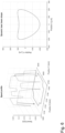
- Fig. 6 shows another preferred embodiment of the present invention, where the determination of the transition phases between each two consecutive specific dynamic laser beam shapes is executed in dependence of the cutting speed of the laser cutting head, being moved over the workpiece surface for the purpose of cutting.
- the speed profile is depicted for the same cutting contour, as shown in figure 5 .
- a specific dynamic laser beam shape is depicted, which is allocated by the allocation tool 102 for the point in the cutting segment within the cutting contour, which is shown on the left-hand side by the star (on the lower left corner of the cutting contour).
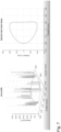
- Fig. 7 still shows another preferred embodiment of the present invention, where the determination of the transition phases between each two consecutive specific dynamic laser beam shapes is executed dependent on the jerk. Accordingly, on the left-hand side of figure 7 a jerk profile is depicted for the contour, which is also the basis of figures 5 and 6 . On the right-hand side of figure 7 an allocated dynamic laser beam shape is depicted, which is allocated to a cutting segment, which comprises the "star", as depicted on the left-hand side of figure 7 (upper right corner of the contour).
- a part has different geometrical dimensions and shapes, which result in different conditions for the laser cutting process (e.g., cutting speed).
- optimal laser beam shapes can be found for each of these segments.
- a corner segment may have other cutting properties than a straight-line segment, which generally, may be cut with higher cutting speed.
- the transition between the segments will be performed in a smooth way (continuous transition between segments). At least, the following segments are relevant:
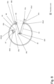
- Fig. 8 shows an example cutting contour with mainly two different cutting segments and with different transition zones or transitions phases.
- the cutting contour comprises a part of a circle element with one circle cut-out and a small circle cutting segment above the cut-out and in the upper right portion of the circle cutting contour.
- the transition zones are depicted in figure 8 by a left hatched pattern.
- Reference numeral 81a depicts a "pierce in” cutting segment for the outer circle cutting contour.
- Reference numeral 81a2 represents the dynamic laser beam shaping transition zone or pattern from segment 81a to segment 82a.
- the latter segment 82a represents a "lead in straight” cutting segment.
- Reference numeral 82a3 depicts that dynamic laser beam shaping transition zone between segment 82a to segment 83.
- the latter segment 83 represents “straight-line” cutting segment, there the laser cutting head may be moved quicker compared to corner segments.
- Reference numeral 834 represents the dynamic laser beam shaping transition zone or phase between segment 83 and segment 84.
- the segment 84 is “right turn corner” cutting segment.
- Reference numeral 845 represents the dynamic laser beam shaping transition zone or phase between segment 84 and segment 85. Segment 85 refers to another straight-line cutting segment.
- Reference numeral 856 represents a dynamic laser beam shaping transition zone or phase between segment 85 and segment 86. Segment 86 represents a "left turn corner” cutting segment
- the contour further comprises of another circle cutting segment, represented in figure 8 by reference numeral 87.
- This circle contour has a "pierce in” cutting segment, represented in figure 8 with reference 81b.
- the dynamic laser beam shaping transition zone between segment 81b and segment 82b is represented in figure 8 with the reference numeral 81b2b.
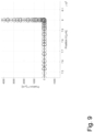
- Fig. 9 shows a position-based diagram for the different dynamic laser beam shapes and its transition phases in between, there the laser beam shape is oriented in cutting direction, where cutting is first in X direction followed by cutting in Y direction.
Landscapes
- Physics & Mathematics (AREA)
- Optics & Photonics (AREA)
- Engineering & Computer Science (AREA)
- Plasma & Fusion (AREA)
- Mechanical Engineering (AREA)
- Laser Beam Processing (AREA)
Priority Applications (6)
| Application Number | Priority Date | Filing Date | Title |
|---|---|---|---|
| EP21204469.7A EP4169654A1 (de) | 2021-10-25 | 2021-10-25 | Bestimmung von übergangsphasen zur transformation unterschiedlicher dynamischer laserstrahlformen für eine laserschneidmaschine |
| JP2024524652A JP7590628B2 (ja) | 2021-10-25 | 2022-10-24 | レーザ切断機のための異なる動的レーザビーム形状を変形させるための遷移相の決定 |
| CN202280071641.9A CN118159385B (zh) | 2021-10-25 | 2022-10-24 | 用于转换激光切割机的不同动态激光束形状的过渡阶段的确定 |
| US18/701,001 US12275085B2 (en) | 2021-10-25 | 2022-10-24 | Determination of transition phases for transforming different dynamic laser beam shapes for a laser cutting machine |
| PCT/EP2022/079622 WO2023072845A1 (en) | 2021-10-25 | 2022-10-24 | Determination of transition phases for transforming different dynamic laser beam shapes for a laser cutting machine |
| EP22809373.8A EP4422820B1 (de) | 2021-10-25 | 2022-10-24 | Bestimmung von übergangsphasen zur transformation unterschiedlicher dynamischer laserstrahlformen für eine laserschneidmaschine |
Applications Claiming Priority (1)
| Application Number | Priority Date | Filing Date | Title |
|---|---|---|---|
| EP21204469.7A EP4169654A1 (de) | 2021-10-25 | 2021-10-25 | Bestimmung von übergangsphasen zur transformation unterschiedlicher dynamischer laserstrahlformen für eine laserschneidmaschine |
Publications (1)
| Publication Number | Publication Date |
|---|---|
| EP4169654A1 true EP4169654A1 (de) | 2023-04-26 |
Family
ID=78621648
Family Applications (2)
| Application Number | Title | Priority Date | Filing Date |
|---|---|---|---|
| EP21204469.7A Withdrawn EP4169654A1 (de) | 2021-10-25 | 2021-10-25 | Bestimmung von übergangsphasen zur transformation unterschiedlicher dynamischer laserstrahlformen für eine laserschneidmaschine |
| EP22809373.8A Active EP4422820B1 (de) | 2021-10-25 | 2022-10-24 | Bestimmung von übergangsphasen zur transformation unterschiedlicher dynamischer laserstrahlformen für eine laserschneidmaschine |
Family Applications After (1)
| Application Number | Title | Priority Date | Filing Date |
|---|---|---|---|
| EP22809373.8A Active EP4422820B1 (de) | 2021-10-25 | 2022-10-24 | Bestimmung von übergangsphasen zur transformation unterschiedlicher dynamischer laserstrahlformen für eine laserschneidmaschine |
Country Status (5)
| Country | Link |
|---|---|
| US (1) | US12275085B2 (de) |
| EP (2) | EP4169654A1 (de) |
| JP (1) | JP7590628B2 (de) |
| CN (1) | CN118159385B (de) |
| WO (1) | WO2023072845A1 (de) |
Families Citing this family (1)
| Publication number | Priority date | Publication date | Assignee | Title |
|---|---|---|---|---|
| CN120406100B (zh) * | 2025-07-02 | 2025-09-23 | 深圳市鹏鼎智控科技有限公司 | 一种基于大数据的激光振镜智能控制系统及方法 |
Citations (5)
| Publication number | Priority date | Publication date | Assignee | Title |
|---|---|---|---|---|
| US20100059490A1 (en) * | 2008-09-09 | 2010-03-11 | Electro Scientific Industries, Inc. | Adaptive optic beamshaping in laser processing systems |
| WO2019145536A1 (en) | 2018-01-29 | 2019-08-01 | Bystronic Laser Ag | Optical device for shaping an electromagnetic wave beam and use thereof, beam treatment device and use thereof, and beam treatment method |
| WO2019179603A1 (de) * | 2018-03-20 | 2019-09-26 | Robert Bosch Gmbh | Verfahren und vorrichtung zur prozessorientierten strahlformanpassung und strahlorientierung |
| US20200298335A1 (en) * | 2019-03-18 | 2020-09-24 | Fanuc Corporation | Laser machining method for cutting workpiece |
| US20200331096A1 (en) * | 2019-04-19 | 2020-10-22 | Fanuc Corporation | Device and method for learning focal position offset of laser processing apparatus, and laser processing system correcting focal position offset |
Family Cites Families (12)
| Publication number | Priority date | Publication date | Assignee | Title |
|---|---|---|---|---|
| JPH0780674A (ja) * | 1993-09-17 | 1995-03-28 | Hitachi Constr Mach Co Ltd | レーザ加工方法及びレーザ加工装置 |
| IL121890A (en) * | 1997-10-06 | 2000-11-21 | Dov Zahavi | Laser assisted polishing |
| US6639177B2 (en) * | 2001-03-29 | 2003-10-28 | Gsi Lumonics Corporation | Method and system for processing one or more microstructures of a multi-material device |
| JP2006007257A (ja) * | 2004-06-24 | 2006-01-12 | Matsushita Electric Ind Co Ltd | レーザ加工装置 |
| US8350187B2 (en) * | 2009-03-28 | 2013-01-08 | Electro Scientific Industries, Inc. | Method and apparatus for laser machining |
| DE102010020183B4 (de) * | 2010-05-11 | 2013-07-11 | Precitec Kg | Laserschneidkopf und Verfahren zum Schneiden eines Werkstücks mittels eines Laserschneidkopfes |
| JP6025652B2 (ja) * | 2013-05-15 | 2016-11-16 | 株式会社アマダホールディングス | レーザ加工方法及びレーザ加工プログラム作成装置 |
| US11780029B2 (en) * | 2014-03-05 | 2023-10-10 | Panasonic Connect North America, division of Panasonic Corporation of North America | Material processing utilizing a laser having a variable beam shape |
| US10663742B2 (en) * | 2016-09-29 | 2020-05-26 | Nlight, Inc. | Method and system for cutting a material using a laser having adjustable beam characteristics |
| EP3671373A1 (de) * | 2018-12-19 | 2020-06-24 | Bystronic Laser AG | Prognoseverfahren zur prognose eines bearbeitungsergebnisses für ein laserbearbeitungsverfahren |
| US12332573B2 (en) * | 2019-09-05 | 2025-06-17 | Asml Netherlands B.V. | Method for determining defectiveness of pattern based on after development image |
| US20230321750A1 (en) * | 2020-08-27 | 2023-10-12 | Mitsubishi Electric Corporation | Laser machining apparatus |
-
2021
- 2021-10-25 EP EP21204469.7A patent/EP4169654A1/de not_active Withdrawn
-
2022
- 2022-10-24 WO PCT/EP2022/079622 patent/WO2023072845A1/en not_active Ceased
- 2022-10-24 JP JP2024524652A patent/JP7590628B2/ja active Active
- 2022-10-24 CN CN202280071641.9A patent/CN118159385B/zh active Active
- 2022-10-24 US US18/701,001 patent/US12275085B2/en active Active
- 2022-10-24 EP EP22809373.8A patent/EP4422820B1/de active Active
Patent Citations (5)
| Publication number | Priority date | Publication date | Assignee | Title |
|---|---|---|---|---|
| US20100059490A1 (en) * | 2008-09-09 | 2010-03-11 | Electro Scientific Industries, Inc. | Adaptive optic beamshaping in laser processing systems |
| WO2019145536A1 (en) | 2018-01-29 | 2019-08-01 | Bystronic Laser Ag | Optical device for shaping an electromagnetic wave beam and use thereof, beam treatment device and use thereof, and beam treatment method |
| WO2019179603A1 (de) * | 2018-03-20 | 2019-09-26 | Robert Bosch Gmbh | Verfahren und vorrichtung zur prozessorientierten strahlformanpassung und strahlorientierung |
| US20200298335A1 (en) * | 2019-03-18 | 2020-09-24 | Fanuc Corporation | Laser machining method for cutting workpiece |
| US20200331096A1 (en) * | 2019-04-19 | 2020-10-22 | Fanuc Corporation | Device and method for learning focal position offset of laser processing apparatus, and laser processing system correcting focal position offset |
Non-Patent Citations (1)
| Title |
|---|
| CINDY GOPPOLDTHOMAS PINDERPATRICK HERWIG: "Dynamic beam shaping for thick sheet metal cutting", LASERS IN MANUFACTURING CONFERENCE, 2017 |
Also Published As
| Publication number | Publication date |
|---|---|
| US20240335904A1 (en) | 2024-10-10 |
| EP4422820A1 (de) | 2024-09-04 |
| WO2023072845A9 (en) | 2024-03-21 |
| WO2023072845A1 (en) | 2023-05-04 |
| US12275085B2 (en) | 2025-04-15 |
| JP7590628B2 (ja) | 2024-11-26 |
| CN118159385A (zh) | 2024-06-07 |
| CN118159385B (zh) | 2025-07-29 |
| JP2024539285A (ja) | 2024-10-28 |
| EP4422820B1 (de) | 2025-08-06 |
Similar Documents
| Publication | Publication Date | Title |
|---|---|---|
| EP4392200B1 (de) | Automatische bestimmung einer dynamischen laserstrahlform für eine laserschneidmaschine | |
| US10780577B2 (en) | Machine learning device, robot system, and machine learning method for learning operations of robot and laser scanner | |
| CN110268402B (zh) | 用于在增材制造过程中提供珠粒尺寸变化以提高沉积层的几何精度的系统和方法 | |
| EP4422820B1 (de) | Bestimmung von übergangsphasen zur transformation unterschiedlicher dynamischer laserstrahlformen für eine laserschneidmaschine | |
| CN116588084B (zh) | 一种车辆的泊车路径规划方法、装置、设备以及存储介质 | |
| US20150021304A1 (en) | Laser machining method, laser machining apparatus, and laser machining program | |
| JP2019150902A (ja) | 工具経路を生成するための方法及び装置 | |
| CN114025912A (zh) | 加工条件搜索装置以及加工条件搜索方法 | |
| JP5274714B1 (ja) | 加工プログラム生成装置、加工プログラム生成方法、および加工プログラム生成プログラム | |
| US20180178318A1 (en) | Data generating device setting machining condition suitable for foil placed on workpiece to be machined by irradiating laser beam thereon | |
| Pham et al. | Reinforcement learning-based laser cutting machine parameter optimization | |
| US10350706B2 (en) | Laser processing system and recording medium storing computer readable programs for controlling the same | |
| JP2016187830A (ja) | レーザ加工装置 | |
| US11467556B2 (en) | System and method for projection of light pattern on work-piece | |
| Wang et al. | Prediction of toolpath redundancy for NC machining of free-form surfaces based on automatic recognition of steep-wall features | |
| Shrivastava et al. | Grey relational analysis based particle swarm optimisation (PSO) of quality characteristics in laser cutting of titanium alloy sheet | |
| CN212526539U (zh) | 一种异型孔激光加工装置 | |
| JP7367591B2 (ja) | レーザ加工装置 | |
| CN121613827A (zh) | 基于几何特征的机器人工艺路径数据处理方法及装置 | |
| Qiu et al. | Research on Performance Improvement of Deep Learning Models for Small Target Detection | |
| JP2017064735A (ja) | 加工データ作成装置と、その制御プログラム及び加工データの作成方法 | |
| US20240028004A1 (en) | Machine-learning device, control device, and machine-learning method | |
| CN120014253A (zh) | 点云语义分割方法及装置 | |
| JP2021137840A (ja) | レーザ加工システム、制御装置、及び制御プログラム |
Legal Events
| Date | Code | Title | Description |
|---|---|---|---|
| PUAI | Public reference made under article 153(3) epc to a published international application that has entered the european phase |
Free format text: ORIGINAL CODE: 0009012 |
|
| STAA | Information on the status of an ep patent application or granted ep patent |
Free format text: STATUS: THE APPLICATION HAS BEEN PUBLISHED |
|
| AK | Designated contracting states |
Kind code of ref document: A1 Designated state(s): AL AT BE BG CH CY CZ DE DK EE ES FI FR GB GR HR HU IE IS IT LI LT LU LV MC MK MT NL NO PL PT RO RS SE SI SK SM TR |
|
| STAA | Information on the status of an ep patent application or granted ep patent |
Free format text: STATUS: THE APPLICATION IS DEEMED TO BE WITHDRAWN |
|
| 18D | Application deemed to be withdrawn |
Effective date: 20231027 |