EP4169680A1 - Dispositif de guidage de conduites - Google Patents
Dispositif de guidage de conduites Download PDFInfo
- Publication number
- EP4169680A1 EP4169680A1 EP22200750.2A EP22200750A EP4169680A1 EP 4169680 A1 EP4169680 A1 EP 4169680A1 EP 22200750 A EP22200750 A EP 22200750A EP 4169680 A1 EP4169680 A1 EP 4169680A1
- Authority
- EP
- European Patent Office
- Prior art keywords
- axis
- arm
- robot
- restoring
- swivel arm
- Prior art date
- Legal status (The legal status is an assumption and is not a legal conclusion. Google has not performed a legal analysis and makes no representation as to the accuracy of the status listed.)
- Granted
Links
Images


Classifications
-
- B—PERFORMING OPERATIONS; TRANSPORTING
- B25—HAND TOOLS; PORTABLE POWER-DRIVEN TOOLS; MANIPULATORS
- B25J—MANIPULATORS; CHAMBERS PROVIDED WITH MANIPULATION DEVICES
- B25J19/00—Accessories fitted to manipulators, e.g. for monitoring, for viewing; Safety devices combined with or specially adapted for use in connection with manipulators
- B25J19/0025—Means for supplying energy to the end effector
Definitions
- the invention relates to a device for guiding cables on an industrial robot according to the preamble of claim 1.
- Devices of the type mentioned have long been known in different configurations, for example from EP 1 179 397 A1 . They are used to guide lines, for example in the form of line packages, on an industrial robot, which are used to supply a tool mounted on the industrial robot with energy or other media. There is a need to route the lines in such a way that they do not impede the movements of the robot axes and are also not damaged by the movements of the robot axes.
- a swivel arm is provided, which is mounted on a robot axis and can then be swiveled about a swivel axis fixed to the robot axis.
- the swivel arm carries a holder at a free end, which fixes the lines or holds them in place so that they can be displaced longitudinally to a limited extent.
- one or more return springs are provided which push the swivel arm back into the rest position with their restoring force.
- the return springs of the previously known devices have large surfaces on which dirt can accumulate and which are difficult to clean. This is particularly disadvantageous for food and drug manufacturing and processing applications.
- the invention is based on the idea of keeping the wire windings of the at least one return spring at a distance from one another, so that they do not rest against one another, but instead there are gaps that allow the spring wire to be cleaned. If the coils of wire do not rest against one another when the swivel arm is in the rest position, cleaning of the spring wire over its entire circumference is possible at least when the swivel arm is in the rest position. It is possible that only one restoring spring acts on the pivot arm with a restoring force, or that two or more restoring springs arranged parallel to one another are provided. These are then expediently structurally identical. The total restoring force applied by the restoring springs is greater, the more restoring springs are used, without these having to be built large.
- each restoring spring is designed as a tension and compression spring which opposes a further restoring force when the pivoting arm pivots in a second pivoting direction opposite to the first pivoting direction when it is compressed against the longitudinal direction. This measure at least makes it more difficult to reduce the distance between the turns.
- their windings are arranged at a mutual distance of at least 3 mm and preferably at least 4 mm. This distance plus the thickness of the spring wire can also be referred to as the pitch of the coil spring.
- the holder is expediently arranged on the swivel arm such that it can be rotated about an axis of rotation, in order to avoid excessive bending of the lines when the robot is moved accordingly.
- the holder is arranged detachably and rotatably about the axis of rotation on a first fastening element, which is fixed on the swivel arm. This measure allows the holder to be replaced, on the one hand when it is worn and on the other hand to replace it with a holder of a different size.
- the pivot axis advantageously extends between two second fastening elements fixed to the robot axis.
- a component that defines the pivot axis and is rotatable with respect to the robot axis is then mounted at both of its ends in one of the second fastening elements, so that it is stably fastened to the robot axis.
- the first fastening element and the second fastening elements are expediently of the same construction, so that fewer different components have to be kept available.
- a counter bearing is advantageously provided for mounting on the robot axis, with each restoring spring being fastened with a first end to the swivel arm and with a second end to the counter bearing.
- the swivel arm and the counter bearing are each provided with notches into which a wire section of the return spring or one of the return springs engages so that it cannot slip in the longitudinal direction of the swivel arm or the counter bearing.
- the notches suitably run around the counter bearing or the swivel arm.
- the device according to the invention can also have a mounting element, for example a metal sheet, for mounting on the robot axis on which the Pivot arm is arranged pivotable about the pivot axis.
- the stop and/or the counter bearing can also be arranged on the mounting element. The entire device can then be prefabricated and mounted on the robot axis by mounting the mounting element.
- a six-axis industrial robot 10 is shown in part, on whose third robot axis 12 a device 14 for guiding lines combined in a line package 16 is mounted.
- the lines of the line package 16 are surrounded by a protective hose 18 .
- the guide device 14 has a mounting element in the form of a mounting plate 20 on which a pivot arm 22 is arranged pivotable about a pivot axis 24 . Since the mounting plate 20 is fixed to the third robot axis 12, the pivot axis 24 is fixed to the robot axis. Arranged on a free end of the pivot arm 22 facing away from the pivot axis 24 is a holder 26 which surrounds the line package 16 and holds it in place. In order to fasten the holder 26 to the swivel arm 22 , a first fastening element 28 is mounted on the latter, on which the holder 26 is fastened so that it can rotate about an axis of rotation 30 .
- the pivot axis 24 is the central longitudinal axis of a tubular pivot element 34 arranged between two second fastening elements 32, the ends of which are each accommodated in one of the two second fastening elements 32 so as to be rotatable about the pivot axis 24, and on which the pivot arm 22 is fixed.
- the second fasteners 32 are in turn fixed to the mounting plate 20. They are identical in construction and also identical in construction to the first fastening element 28.
- a rod-shaped counter bearing 36 is mounted on the mounting plate 20 at a distance from the swivel arm 22 .
- Extending between the pivot axis 24 and the counter bearing 36 are two restoring springs 28 of the same construction, each designed as a cylindrical helical spring and as a tension spring, each of which is fastened with its first end 40 to the pivot arm 22 and with its second end 42 to the counter bearing 36. If the swivel arm 22 is swiveled from the rest position shown in the drawing in a first swivel direction 44 about the swivel axis 24, the restoring springs 38 are stretched in a longitudinal direction 46 and apply a restoring force.
- a pivoting of the pivoting arm 22 in a second pivoting direction 48 opposite to the first pivoting direction 44 out of the rest position is prevented by a stop 50 arranged on the mounting plate 20 against which the pivoting arm 22 bears in the rest position.
- return springs 38 can also be embodied as compression springs at the same time, which, due to their compression against longitudinal direction 46, counteract the pivoting of pivot arm 22 out of the rest position in the second pivot direction 48 with a further restoring force.
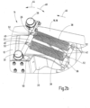
- the return springs 38 are, as in Figure 2a , b shown in detail, constructed and arranged with their turns spaced from each other. The distance between two consecutive turns viewed in the longitudinal direction 46 is at least 3 mm. Both the swivel arm 22 and the counter bearing 36 are each provided with two circumferential notches 52, in each of which a hook-shaped bent wire section is hooked at the first and second end 40, 42 of the relevant return spring 38.
- the invention relates to a device 14 for guiding lines 16 on an industrial robot 10 with a swivel arm 22 for mounting on a robot axis 12 in a fixed position about a robot axis Pivot axis 24 pivotable arrangement, with a bracket 26 mounted on the pivot arm 22 for the lines 16 and with at least one return spring 38, against whose restoring force the pivot arm 22 can be pivoted in a first pivot direction 44 from a rest position.
- the at least one restoring spring 38 is a tension spring designed as a helical spring that can be stretched in a longitudinal direction 46 against the restoring force, the coils of which are arranged at a distance from one another in the longitudinal direction 46 when the swivel arm 22 is in the rest position.
Landscapes
- Engineering & Computer Science (AREA)
- Robotics (AREA)
- Mechanical Engineering (AREA)
- Manipulator (AREA)
Applications Claiming Priority (1)
| Application Number | Priority Date | Filing Date | Title |
|---|---|---|---|
| DE102021127283.1A DE102021127283A1 (de) | 2021-10-21 | 2021-10-21 | Vorrichtung zur Führung von Leitungen |
Publications (2)
| Publication Number | Publication Date |
|---|---|
| EP4169680A1 true EP4169680A1 (fr) | 2023-04-26 |
| EP4169680B1 EP4169680B1 (fr) | 2024-06-12 |
Family
ID=84044917
Family Applications (1)
| Application Number | Title | Priority Date | Filing Date |
|---|---|---|---|
| EP22200750.2A Active EP4169680B1 (fr) | 2021-10-21 | 2022-10-11 | Dispositif de guidage de conduites |
Country Status (3)
| Country | Link |
|---|---|
| EP (1) | EP4169680B1 (fr) |
| DE (1) | DE102021127283A1 (fr) |
| ES (1) | ES2985503T3 (fr) |
Citations (3)
| Publication number | Priority date | Publication date | Assignee | Title |
|---|---|---|---|---|
| EP1179397A1 (fr) | 2000-07-14 | 2002-02-13 | Abb Ab | Manipulateur équipé d'un dispositif pour soutenir les cables d'alimentation |
| EP1284177B1 (fr) * | 2001-08-14 | 2006-11-15 | Cimlec Industrie | Dispositif de maintien d'éléments de faisceau de transport d'énergie à un automate et son application à un robot de soudage |
| EP2913162B1 (fr) * | 2014-02-28 | 2020-09-23 | Sumcab Specialcable GmbH | Système de retour de conduite |
-
2021
- 2021-10-21 DE DE102021127283.1A patent/DE102021127283A1/de not_active Withdrawn
-
2022
- 2022-10-11 ES ES22200750T patent/ES2985503T3/es active Active
- 2022-10-11 EP EP22200750.2A patent/EP4169680B1/fr active Active
Patent Citations (3)
| Publication number | Priority date | Publication date | Assignee | Title |
|---|---|---|---|---|
| EP1179397A1 (fr) | 2000-07-14 | 2002-02-13 | Abb Ab | Manipulateur équipé d'un dispositif pour soutenir les cables d'alimentation |
| EP1284177B1 (fr) * | 2001-08-14 | 2006-11-15 | Cimlec Industrie | Dispositif de maintien d'éléments de faisceau de transport d'énergie à un automate et son application à un robot de soudage |
| EP2913162B1 (fr) * | 2014-02-28 | 2020-09-23 | Sumcab Specialcable GmbH | Système de retour de conduite |
Also Published As
| Publication number | Publication date |
|---|---|
| ES2985503T3 (es) | 2024-11-06 |
| DE102021127283A1 (de) | 2023-04-27 |
| EP4169680B1 (fr) | 2024-06-12 |
Similar Documents
| Publication | Publication Date | Title |
|---|---|---|
| DE102012100290B4 (de) | Gelenkige Schutz- und Führungsvorrichtung für Kabel und Schläuche | |
| DE102008007552B4 (de) | Vorrichtung zur Erhöhung der Biegesteifigkeit von Schläuchen | |
| EP2913162B1 (fr) | Système de retour de conduite | |
| DE602004005369T2 (de) | Vorrichtung zum Verlegen von Leitungselementen | |
| DE102010043121A1 (de) | Roboteranordnung mit einem Führungselement für Versorgungsleitungen | |
| DE102007018543B4 (de) | Vorrichtung zum Führen von Versorgungsleitungen entlang der Struktur eines Industrieroboters | |
| DE102009037515B4 (de) | Vorrichtung und Verfahren zum Führen von Versorgungsleitungen an einem Gelenkroboter | |
| DE102009037516A1 (de) | Vorrichtung und Verfahren zum Führen von Versorungsleitungen an einem Gelenkroboter | |
| EP4169680B1 (fr) | Dispositif de guidage de conduites | |
| DE102009043454B4 (de) | Rillschlauchspannvorrichtung | |
| EP3000551B1 (fr) | Machine à souder pour grillage | |
| DE102007062332A1 (de) | Roboterarm | |
| DE102017109923A1 (de) | Vorschubvorrichtung | |
| EP2448723B1 (fr) | Dispositif pour guider une ligne électrique ou une conduite | |
| DE102008051628A1 (de) | Vorrichtung und Verfahren zum Führen von Versorgungsleitungen entlang der Struktur eines Industrieroboters | |
| DE102017105024A1 (de) | Greifeinrichtung, Rinsersystem und Verfahren zum Greifen, Halten und Führen von Behältern | |
| EP3168495A1 (fr) | Chaine de guidage d'energie dotee d'element de renfort | |
| DE202018004030U1 (de) | Gelenkverbindung an den starren Segmenten einer Endlos-Kletterwand | |
| EP3161197B1 (fr) | Dispositif de pression servant à presser un flexible tressé sur une partie centrale d'élément et tresseuse | |
| DE102017106871A1 (de) | Vorschubeinrichtung und Reinigungsgerät | |
| EP1747609A1 (fr) | Transmetteur rotatif pour des raccords de cable | |
| EP2422946A1 (fr) | Dispositif de transmission pour rayonnement | |
| DE102020125385B4 (de) | Vorrichtung zur Befestigung eines Leitungspakets | |
| DE10227924B4 (de) | Silo-Austragvorrichtung | |
| DE2047366C3 (de) | Schaber- oder Wischervorrichtung |
Legal Events
| Date | Code | Title | Description |
|---|---|---|---|
| PUAI | Public reference made under article 153(3) epc to a published international application that has entered the european phase |
Free format text: ORIGINAL CODE: 0009012 |
|
| STAA | Information on the status of an ep patent application or granted ep patent |
Free format text: STATUS: THE APPLICATION HAS BEEN PUBLISHED |
|
| AK | Designated contracting states |
Kind code of ref document: A1 Designated state(s): AL AT BE BG CH CY CZ DE DK EE ES FI FR GB GR HR HU IE IS IT LI LT LU LV MC ME MK MT NL NO PL PT RO RS SE SI SK SM TR |
|
| STAA | Information on the status of an ep patent application or granted ep patent |
Free format text: STATUS: REQUEST FOR EXAMINATION WAS MADE |
|
| 17P | Request for examination filed |
Effective date: 20230914 |
|
| RBV | Designated contracting states (corrected) |
Designated state(s): AL AT BE BG CH CY CZ DE DK EE ES FI FR GB GR HR HU IE IS IT LI LT LU LV MC ME MK MT NL NO PL PT RO RS SE SI SK SM TR |
|
| GRAP | Despatch of communication of intention to grant a patent |
Free format text: ORIGINAL CODE: EPIDOSNIGR1 |
|
| STAA | Information on the status of an ep patent application or granted ep patent |
Free format text: STATUS: GRANT OF PATENT IS INTENDED |
|
| INTG | Intention to grant announced |
Effective date: 20240130 |
|
| GRAJ | Information related to disapproval of communication of intention to grant by the applicant or resumption of examination proceedings by the epo deleted |
Free format text: ORIGINAL CODE: EPIDOSDIGR1 |
|
| STAA | Information on the status of an ep patent application or granted ep patent |
Free format text: STATUS: REQUEST FOR EXAMINATION WAS MADE |
|
| GRAS | Grant fee paid |
Free format text: ORIGINAL CODE: EPIDOSNIGR3 |
|
| STAA | Information on the status of an ep patent application or granted ep patent |
Free format text: STATUS: GRANT OF PATENT IS INTENDED |
|
| GRAP | Despatch of communication of intention to grant a patent |
Free format text: ORIGINAL CODE: EPIDOSNIGR1 |
|
| GRAA | (expected) grant |
Free format text: ORIGINAL CODE: 0009210 |
|
| STAA | Information on the status of an ep patent application or granted ep patent |
Free format text: STATUS: THE PATENT HAS BEEN GRANTED |
|
| INTC | Intention to grant announced (deleted) | ||
| INTG | Intention to grant announced |
Effective date: 20240506 |
|
| AK | Designated contracting states |
Kind code of ref document: B1 Designated state(s): AL AT BE BG CH CY CZ DE DK EE ES FI FR GB GR HR HU IE IS IT LI LT LU LV MC ME MK MT NL NO PL PT RO RS SE SI SK SM TR |
|
| REG | Reference to a national code |
Ref country code: GB Ref legal event code: FG4D Free format text: NOT ENGLISH |
|
| REG | Reference to a national code |
Ref country code: CH Ref legal event code: EP |
|
| REG | Reference to a national code |
Ref country code: IE Ref legal event code: FG4D Free format text: LANGUAGE OF EP DOCUMENT: GERMAN |
|
| REG | Reference to a national code |
Ref country code: DE Ref legal event code: R096 Ref document number: 502022001037 Country of ref document: DE |
|
| P01 | Opt-out of the competence of the unified patent court (upc) registered |
Free format text: CASE NUMBER: APP_40181/2024 Effective date: 20240705 |
|
| PG25 | Lapsed in a contracting state [announced via postgrant information from national office to epo] |
Ref country code: BG Free format text: LAPSE BECAUSE OF FAILURE TO SUBMIT A TRANSLATION OF THE DESCRIPTION OR TO PAY THE FEE WITHIN THE PRESCRIBED TIME-LIMIT Effective date: 20240612 |
|
| PG25 | Lapsed in a contracting state [announced via postgrant information from national office to epo] |
Ref country code: FI Free format text: LAPSE BECAUSE OF FAILURE TO SUBMIT A TRANSLATION OF THE DESCRIPTION OR TO PAY THE FEE WITHIN THE PRESCRIBED TIME-LIMIT Effective date: 20240612 Ref country code: HR Free format text: LAPSE BECAUSE OF FAILURE TO SUBMIT A TRANSLATION OF THE DESCRIPTION OR TO PAY THE FEE WITHIN THE PRESCRIBED TIME-LIMIT Effective date: 20240612 |
|
| REG | Reference to a national code |
Ref country code: LT Ref legal event code: MG9D |
|
| REG | Reference to a national code |
Ref country code: NL Ref legal event code: MP Effective date: 20240612 |
|
| PG25 | Lapsed in a contracting state [announced via postgrant information from national office to epo] |
Ref country code: LV Free format text: LAPSE BECAUSE OF FAILURE TO SUBMIT A TRANSLATION OF THE DESCRIPTION OR TO PAY THE FEE WITHIN THE PRESCRIBED TIME-LIMIT Effective date: 20240612 |
|
| PG25 | Lapsed in a contracting state [announced via postgrant information from national office to epo] |
Ref country code: NO Free format text: LAPSE BECAUSE OF FAILURE TO SUBMIT A TRANSLATION OF THE DESCRIPTION OR TO PAY THE FEE WITHIN THE PRESCRIBED TIME-LIMIT Effective date: 20240912 Ref country code: LV Free format text: LAPSE BECAUSE OF FAILURE TO SUBMIT A TRANSLATION OF THE DESCRIPTION OR TO PAY THE FEE WITHIN THE PRESCRIBED TIME-LIMIT Effective date: 20240612 Ref country code: HR Free format text: LAPSE BECAUSE OF FAILURE TO SUBMIT A TRANSLATION OF THE DESCRIPTION OR TO PAY THE FEE WITHIN THE PRESCRIBED TIME-LIMIT Effective date: 20240612 Ref country code: FI Free format text: LAPSE BECAUSE OF FAILURE TO SUBMIT A TRANSLATION OF THE DESCRIPTION OR TO PAY THE FEE WITHIN THE PRESCRIBED TIME-LIMIT Effective date: 20240612 Ref country code: BG Free format text: LAPSE BECAUSE OF FAILURE TO SUBMIT A TRANSLATION OF THE DESCRIPTION OR TO PAY THE FEE WITHIN THE PRESCRIBED TIME-LIMIT Effective date: 20240612 Ref country code: RS Free format text: LAPSE BECAUSE OF FAILURE TO SUBMIT A TRANSLATION OF THE DESCRIPTION OR TO PAY THE FEE WITHIN THE PRESCRIBED TIME-LIMIT Effective date: 20240912 |
|
| REG | Reference to a national code |
Ref country code: ES Ref legal event code: FG2A Ref document number: 2985503 Country of ref document: ES Kind code of ref document: T3 Effective date: 20241106 |
|
| PG25 | Lapsed in a contracting state [announced via postgrant information from national office to epo] |
Ref country code: NL Free format text: LAPSE BECAUSE OF FAILURE TO SUBMIT A TRANSLATION OF THE DESCRIPTION OR TO PAY THE FEE WITHIN THE PRESCRIBED TIME-LIMIT Effective date: 20240612 |
|
| PG25 | Lapsed in a contracting state [announced via postgrant information from national office to epo] |
Ref country code: NL Free format text: LAPSE BECAUSE OF FAILURE TO SUBMIT A TRANSLATION OF THE DESCRIPTION OR TO PAY THE FEE WITHIN THE PRESCRIBED TIME-LIMIT Effective date: 20240612 |
|
| PG25 | Lapsed in a contracting state [announced via postgrant information from national office to epo] |
Ref country code: PT Free format text: LAPSE BECAUSE OF FAILURE TO SUBMIT A TRANSLATION OF THE DESCRIPTION OR TO PAY THE FEE WITHIN THE PRESCRIBED TIME-LIMIT Effective date: 20241014 |
|
| PG25 | Lapsed in a contracting state [announced via postgrant information from national office to epo] |
Ref country code: PT Free format text: LAPSE BECAUSE OF FAILURE TO SUBMIT A TRANSLATION OF THE DESCRIPTION OR TO PAY THE FEE WITHIN THE PRESCRIBED TIME-LIMIT Effective date: 20241014 |
|
| PG25 | Lapsed in a contracting state [announced via postgrant information from national office to epo] |
Ref country code: PL Free format text: LAPSE BECAUSE OF FAILURE TO SUBMIT A TRANSLATION OF THE DESCRIPTION OR TO PAY THE FEE WITHIN THE PRESCRIBED TIME-LIMIT Effective date: 20240612 |
|
| PG25 | Lapsed in a contracting state [announced via postgrant information from national office to epo] |
Ref country code: EE Free format text: LAPSE BECAUSE OF FAILURE TO SUBMIT A TRANSLATION OF THE DESCRIPTION OR TO PAY THE FEE WITHIN THE PRESCRIBED TIME-LIMIT Effective date: 20240612 |
|
| PG25 | Lapsed in a contracting state [announced via postgrant information from national office to epo] |
Ref country code: IS Free format text: LAPSE BECAUSE OF FAILURE TO SUBMIT A TRANSLATION OF THE DESCRIPTION OR TO PAY THE FEE WITHIN THE PRESCRIBED TIME-LIMIT Effective date: 20241012 |
|
| PG25 | Lapsed in a contracting state [announced via postgrant information from national office to epo] |
Ref country code: CZ Free format text: LAPSE BECAUSE OF FAILURE TO SUBMIT A TRANSLATION OF THE DESCRIPTION OR TO PAY THE FEE WITHIN THE PRESCRIBED TIME-LIMIT Effective date: 20240612 |
|
| PG25 | Lapsed in a contracting state [announced via postgrant information from national office to epo] |
Ref country code: RO Free format text: LAPSE BECAUSE OF FAILURE TO SUBMIT A TRANSLATION OF THE DESCRIPTION OR TO PAY THE FEE WITHIN THE PRESCRIBED TIME-LIMIT Effective date: 20240612 Ref country code: SK Free format text: LAPSE BECAUSE OF FAILURE TO SUBMIT A TRANSLATION OF THE DESCRIPTION OR TO PAY THE FEE WITHIN THE PRESCRIBED TIME-LIMIT Effective date: 20240612 |
|
| PG25 | Lapsed in a contracting state [announced via postgrant information from national office to epo] |
Ref country code: SM Free format text: LAPSE BECAUSE OF FAILURE TO SUBMIT A TRANSLATION OF THE DESCRIPTION OR TO PAY THE FEE WITHIN THE PRESCRIBED TIME-LIMIT Effective date: 20240612 |
|
| PG25 | Lapsed in a contracting state [announced via postgrant information from national office to epo] |
Ref country code: SM Free format text: LAPSE BECAUSE OF FAILURE TO SUBMIT A TRANSLATION OF THE DESCRIPTION OR TO PAY THE FEE WITHIN THE PRESCRIBED TIME-LIMIT Effective date: 20240612 Ref country code: SK Free format text: LAPSE BECAUSE OF FAILURE TO SUBMIT A TRANSLATION OF THE DESCRIPTION OR TO PAY THE FEE WITHIN THE PRESCRIBED TIME-LIMIT Effective date: 20240612 Ref country code: RO Free format text: LAPSE BECAUSE OF FAILURE TO SUBMIT A TRANSLATION OF THE DESCRIPTION OR TO PAY THE FEE WITHIN THE PRESCRIBED TIME-LIMIT Effective date: 20240612 Ref country code: PL Free format text: LAPSE BECAUSE OF FAILURE TO SUBMIT A TRANSLATION OF THE DESCRIPTION OR TO PAY THE FEE WITHIN THE PRESCRIBED TIME-LIMIT Effective date: 20240612 Ref country code: IS Free format text: LAPSE BECAUSE OF FAILURE TO SUBMIT A TRANSLATION OF THE DESCRIPTION OR TO PAY THE FEE WITHIN THE PRESCRIBED TIME-LIMIT Effective date: 20241012 Ref country code: EE Free format text: LAPSE BECAUSE OF FAILURE TO SUBMIT A TRANSLATION OF THE DESCRIPTION OR TO PAY THE FEE WITHIN THE PRESCRIBED TIME-LIMIT Effective date: 20240612 Ref country code: CZ Free format text: LAPSE BECAUSE OF FAILURE TO SUBMIT A TRANSLATION OF THE DESCRIPTION OR TO PAY THE FEE WITHIN THE PRESCRIBED TIME-LIMIT Effective date: 20240612 |
|
| REG | Reference to a national code |
Ref country code: DE Ref legal event code: R097 Ref document number: 502022001037 Country of ref document: DE |
|
| PG25 | Lapsed in a contracting state [announced via postgrant information from national office to epo] |
Ref country code: DK Free format text: LAPSE BECAUSE OF FAILURE TO SUBMIT A TRANSLATION OF THE DESCRIPTION OR TO PAY THE FEE WITHIN THE PRESCRIBED TIME-LIMIT Effective date: 20240612 |
|
| PLBE | No opposition filed within time limit |
Free format text: ORIGINAL CODE: 0009261 |
|
| STAA | Information on the status of an ep patent application or granted ep patent |
Free format text: STATUS: NO OPPOSITION FILED WITHIN TIME LIMIT |
|
| 26N | No opposition filed |
Effective date: 20250313 |
|
| PG25 | Lapsed in a contracting state [announced via postgrant information from national office to epo] |
Ref country code: MC Free format text: LAPSE BECAUSE OF FAILURE TO SUBMIT A TRANSLATION OF THE DESCRIPTION OR TO PAY THE FEE WITHIN THE PRESCRIBED TIME-LIMIT Effective date: 20240612 |
|
| PG25 | Lapsed in a contracting state [announced via postgrant information from national office to epo] |
Ref country code: LU Free format text: LAPSE BECAUSE OF NON-PAYMENT OF DUE FEES Effective date: 20241011 Ref country code: BE Free format text: LAPSE BECAUSE OF NON-PAYMENT OF DUE FEES Effective date: 20241031 |
|
| REG | Reference to a national code |
Ref country code: BE Ref legal event code: MM Effective date: 20241031 |
|
| PG25 | Lapsed in a contracting state [announced via postgrant information from national office to epo] |
Ref country code: SE Free format text: LAPSE BECAUSE OF FAILURE TO SUBMIT A TRANSLATION OF THE DESCRIPTION OR TO PAY THE FEE WITHIN THE PRESCRIBED TIME-LIMIT Effective date: 20240612 |
|
| PG25 | Lapsed in a contracting state [announced via postgrant information from national office to epo] |
Ref country code: IE Free format text: LAPSE BECAUSE OF NON-PAYMENT OF DUE FEES Effective date: 20241011 |
|
| PGFP | Annual fee paid to national office [announced via postgrant information from national office to epo] |
Ref country code: DE Payment date: 20250925 Year of fee payment: 4 |
|
| PGFP | Annual fee paid to national office [announced via postgrant information from national office to epo] |
Ref country code: AT Payment date: 20260113 Year of fee payment: 4 |
|
| PGFP | Annual fee paid to national office [announced via postgrant information from national office to epo] |
Ref country code: IT Payment date: 20251031 Year of fee payment: 4 |
|
| PGFP | Annual fee paid to national office [announced via postgrant information from national office to epo] |
Ref country code: FR Payment date: 20251030 Year of fee payment: 4 |
|
| PG25 | Lapsed in a contracting state [announced via postgrant information from national office to epo] |
Ref country code: CY Free format text: LAPSE BECAUSE OF FAILURE TO SUBMIT A TRANSLATION OF THE DESCRIPTION OR TO PAY THE FEE WITHIN THE PRESCRIBED TIME-LIMIT; INVALID AB INITIO Effective date: 20221011 |
|
| PGFP | Annual fee paid to national office [announced via postgrant information from national office to epo] |
Ref country code: ES Payment date: 20251216 Year of fee payment: 4 |
|
| PG25 | Lapsed in a contracting state [announced via postgrant information from national office to epo] |
Ref country code: HU Free format text: LAPSE BECAUSE OF FAILURE TO SUBMIT A TRANSLATION OF THE DESCRIPTION OR TO PAY THE FEE WITHIN THE PRESCRIBED TIME-LIMIT; INVALID AB INITIO Effective date: 20221011 |