EP4169701B1 - Dispositif de mise en forme de matériau composite renforcé de fibres et procédé de mise en forme de matériau composite renforcé de fibres - Google Patents
Dispositif de mise en forme de matériau composite renforcé de fibres et procédé de mise en forme de matériau composite renforcé de fibres Download PDFInfo
- Publication number
- EP4169701B1 EP4169701B1 EP20965847.5A EP20965847A EP4169701B1 EP 4169701 B1 EP4169701 B1 EP 4169701B1 EP 20965847 A EP20965847 A EP 20965847A EP 4169701 B1 EP4169701 B1 EP 4169701B1
- Authority
- EP
- European Patent Office
- Prior art keywords
- molding
- fiber preform
- resin material
- core portion
- fiber
- Prior art date
- Legal status (The legal status is an assumption and is not a legal conclusion. Google has not performed a legal analysis and makes no representation as to the accuracy of the status listed.)
- Active
Links
Images






Classifications
-
- B—PERFORMING OPERATIONS; TRANSPORTING
- B29—WORKING OF PLASTICS; WORKING OF SUBSTANCES IN A PLASTIC STATE IN GENERAL
- B29C—SHAPING OR JOINING OF PLASTICS; SHAPING OF MATERIAL IN A PLASTIC STATE, NOT OTHERWISE PROVIDED FOR; AFTER-TREATMENT OF THE SHAPED PRODUCTS, e.g. REPAIRING
- B29C70/00—Shaping composites, i.e. plastics material comprising reinforcements, fillers or preformed parts, e.g. inserts
- B29C70/04—Shaping composites, i.e. plastics material comprising reinforcements, fillers or preformed parts, e.g. inserts comprising reinforcements only, e.g. self-reinforcing plastics
- B29C70/28—Shaping operations therefor
- B29C70/40—Shaping or impregnating by compression not applied
- B29C70/42—Shaping or impregnating by compression not applied for producing articles of definite length, i.e. discrete articles
- B29C70/46—Shaping or impregnating by compression not applied for producing articles of definite length, i.e. discrete articles using matched moulds, e.g. for deforming sheet moulding compounds [SMC] or prepregs
- B29C70/48—Shaping or impregnating by compression not applied for producing articles of definite length, i.e. discrete articles using matched moulds, e.g. for deforming sheet moulding compounds [SMC] or prepregs and impregnating the reinforcements in the closed mould, e.g. resin transfer moulding [RTM], e.g. by vacuum
-
- B—PERFORMING OPERATIONS; TRANSPORTING
- B29—WORKING OF PLASTICS; WORKING OF SUBSTANCES IN A PLASTIC STATE IN GENERAL
- B29C—SHAPING OR JOINING OF PLASTICS; SHAPING OF MATERIAL IN A PLASTIC STATE, NOT OTHERWISE PROVIDED FOR; AFTER-TREATMENT OF THE SHAPED PRODUCTS, e.g. REPAIRING
- B29C70/00—Shaping composites, i.e. plastics material comprising reinforcements, fillers or preformed parts, e.g. inserts
- B29C70/04—Shaping composites, i.e. plastics material comprising reinforcements, fillers or preformed parts, e.g. inserts comprising reinforcements only, e.g. self-reinforcing plastics
- B29C70/28—Shaping operations therefor
- B29C70/40—Shaping or impregnating by compression not applied
- B29C70/42—Shaping or impregnating by compression not applied for producing articles of definite length, i.e. discrete articles
- B29C70/44—Shaping or impregnating by compression not applied for producing articles of definite length, i.e. discrete articles using isostatic pressure, e.g. pressure difference-moulding, vacuum bag-moulding, autoclave-moulding or expanding rubber-moulding
- B29C70/443—Shaping or impregnating by compression not applied for producing articles of definite length, i.e. discrete articles using isostatic pressure, e.g. pressure difference-moulding, vacuum bag-moulding, autoclave-moulding or expanding rubber-moulding and impregnating by vacuum or injection
-
- B—PERFORMING OPERATIONS; TRANSPORTING
- B29—WORKING OF PLASTICS; WORKING OF SUBSTANCES IN A PLASTIC STATE IN GENERAL
- B29C—SHAPING OR JOINING OF PLASTICS; SHAPING OF MATERIAL IN A PLASTIC STATE, NOT OTHERWISE PROVIDED FOR; AFTER-TREATMENT OF THE SHAPED PRODUCTS, e.g. REPAIRING
- B29C33/00—Moulds or cores; Details thereof or accessories therefor
- B29C33/30—Mounting, exchanging or centering
- B29C33/306—Exchangeable mould parts, e.g. cassette moulds, mould inserts
-
- B—PERFORMING OPERATIONS; TRANSPORTING
- B29—WORKING OF PLASTICS; WORKING OF SUBSTANCES IN A PLASTIC STATE IN GENERAL
- B29C—SHAPING OR JOINING OF PLASTICS; SHAPING OF MATERIAL IN A PLASTIC STATE, NOT OTHERWISE PROVIDED FOR; AFTER-TREATMENT OF THE SHAPED PRODUCTS, e.g. REPAIRING
- B29C33/00—Moulds or cores; Details thereof or accessories therefor
- B29C33/44—Moulds or cores; Details thereof or accessories therefor with means for, or specially constructed to facilitate, the removal of articles, e.g. of undercut articles
-
- B—PERFORMING OPERATIONS; TRANSPORTING
- B29—WORKING OF PLASTICS; WORKING OF SUBSTANCES IN A PLASTIC STATE IN GENERAL
- B29C—SHAPING OR JOINING OF PLASTICS; SHAPING OF MATERIAL IN A PLASTIC STATE, NOT OTHERWISE PROVIDED FOR; AFTER-TREATMENT OF THE SHAPED PRODUCTS, e.g. REPAIRING
- B29C70/00—Shaping composites, i.e. plastics material comprising reinforcements, fillers or preformed parts, e.g. inserts
- B29C70/04—Shaping composites, i.e. plastics material comprising reinforcements, fillers or preformed parts, e.g. inserts comprising reinforcements only, e.g. self-reinforcing plastics
- B29C70/28—Shaping operations therefor
- B29C70/54—Component parts, details or accessories; Auxiliary operations, e.g. feeding or storage of prepregs or SMC after impregnation or during ageing
-
- B—PERFORMING OPERATIONS; TRANSPORTING
- B29—WORKING OF PLASTICS; WORKING OF SUBSTANCES IN A PLASTIC STATE IN GENERAL
- B29C—SHAPING OR JOINING OF PLASTICS; SHAPING OF MATERIAL IN A PLASTIC STATE, NOT OTHERWISE PROVIDED FOR; AFTER-TREATMENT OF THE SHAPED PRODUCTS, e.g. REPAIRING
- B29C70/00—Shaping composites, i.e. plastics material comprising reinforcements, fillers or preformed parts, e.g. inserts
- B29C70/04—Shaping composites, i.e. plastics material comprising reinforcements, fillers or preformed parts, e.g. inserts comprising reinforcements only, e.g. self-reinforcing plastics
- B29C70/28—Shaping operations therefor
- B29C70/54—Component parts, details or accessories; Auxiliary operations, e.g. feeding or storage of prepregs or SMC after impregnation or during ageing
- B29C70/546—Measures for feeding or distributing the matrix material in the reinforcing structure
- B29C70/548—Measures for feeding or distributing the matrix material in the reinforcing structure using distribution constructions, e.g. channels incorporated in or associated with the mould
-
- B—PERFORMING OPERATIONS; TRANSPORTING
- B29—WORKING OF PLASTICS; WORKING OF SUBSTANCES IN A PLASTIC STATE IN GENERAL
- B29D—PRODUCING PARTICULAR ARTICLES FROM PLASTICS OR FROM SUBSTANCES IN A PLASTIC STATE
- B29D99/00—Subject matter not provided for in other groups of this subclass
- B29D99/001—Producing wall or panel-like structures, e.g. for hulls, fuselages, or buildings
- B29D99/0014—Producing wall or panel-like structures, e.g. for hulls, fuselages, or buildings provided with ridges or ribs, e.g. joined ribs
Definitions
- the present disclosure relates to a fiber-reinforced composite material molding device and a fiber-reinforced composite material molding method.
- PTL 1 discloses a method of molding a fiber-reinforced composite material to which resin transfer molding (RTM) is applied, in which a fiber preform is infiltrated by a resin by utilizing a pressure difference between a vacuum pressure and an atmospheric pressure.
- RTM resin transfer molding
- a core material which is a molding tool for forming a composite material, has a large groove serving as a passage for a resin and a large number of small grooves branched from the large groove. The resin is diffused in a surface direction of the fiber preform via the large groove and the small grooves, and the diffused resin infiltrates in a thickness direction of the fiber preform.
- US2018297299A1 discloses a method of forming a composite part having a skin and at least one elongated stiffener extending from the skin, the method comprising: providing a mold having a mold surface and a respective elongated compaction cavity for each stiffener, each compaction cavity opening into the mold surface; for each stiffener: placing a bagged insert including an insert received in a tubular bag in the respective compaction cavity, supporting the stiffener with the bagged insert.
- the resin is cured along a shape of the groove portion and adheres to a surface of the fiber preform.
- the molding tool moves so as to be separated from the surface of the fiber preform, the molding tool does not interfere with the cured resin along the shape of the groove portion.
- the molding tool interferes with the resin that is cured along the shape of the groove portion.
- the molding tool interferes with the resin cured along the shape of the groove portion, the molding tool cannot be moved appropriately, or there is a possibility that the resin cured along the shape of the groove portion is peeled off by moving the molding tool, and a molded product is damaged.
- the present disclosure has been made in view of such circumstances, and an object thereof is to provide a fiber-reinforced composite material molding device and a fiber-reinforced composite material molding method in which a core portion can be moved without interfering with a product, and a resin material can be diffused in a surface direction of a fiber preform to infiltrate into the entire fiber preform.
- a fiber-reinforced composite material molding device includes: a core portion having a first molding surface for molding a fiber preform; a molding tool having a second molding surface for molding the fiber preform and a recessed portion that accommodates the core portion; a sealing member that forms a sealed space by sealing the fiber preform on the molding tool in which the core portion is accommodated in the recessed portion, a suction portion that suctions air from the sealed space to depressurize the sealed space; a resin injection portion that injects a resin material into the fiber preform which is sealed in the sealed space depressurized by the suction portion; and a moving mechanism that separates the first molding surface from the fiber preform including the resin material which is molded by the first molding surface and cured, in which a first groove portion which extends in a predetermined direction and through which the resin material flows is formed on the first molding surface, and the moving mechanism moves the core portion along the predetermined direction in which the first groove portion extends, while maintaining a state in which the first molding
- a fiber-reinforced composite material molding method includes: a disposing step of disposing a core portion having a first molding surface for molding a fiber preform in a recessed portion of a molding tool having a second molding surface for molding the fiber preform; a sealing step of forming a sealed space by sealing the fiber preform on the molding tool in which the core portion is accommodated in the recessed portion, with a sealing member; a resin injection step of suctioning air from the sealed space to depressurize the sealed space and injecting a resin material into the fiber preform sealed in the sealed space; and a moving step of separating the first molding surface from the fiber preform including the resin material which is molded by the first molding surface and cured, in which a first groove portion which extends in a predetermined direction and through which the resin material flows is formed on the first molding surface, and in the moving step, the core portion is moved along the predetermined direction in which the first groove portion extends, while maintaining a state in which the first molding surface is in contact
- a fiber-reinforced composite material molding device and a fiber-reinforced composite material molding method in which a core portion can be moved without interfering with a product, and a resin material can be diffused in a surface direction of a fiber preform to infiltrate into the entire fiber preform.
- Fig. 1 is a perspective view showing a state in which the molding device 100 according to the embodiment of the present disclosure is disassembled.
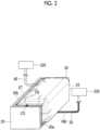
- Fig. 2 is a perspective view showing a state in which the molding device according to the embodiment of the present disclosure is assembled.
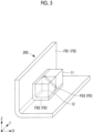
- Fig. 3 is a perspective view showing a composite material molded by the molding device 100 according to the embodiment of the present disclosure.
- a bagging film 30, a suction line 40, and a resin injection line 50 which will be described later, are not illustrated.
- the molding device 100 of the present embodiment includes a pair of core portions 11 and 12, a first curing mold (molding tool) 20, a second curing mold 25, the bagging film (sealing member) 30, the suction line (suction portion) 40, the resin injection line (resin injection portion) 50, and moving mechanisms 61 and 62 (see Fig. 5 described later).
- the molding device 100 of the present embodiment is a device that performs infusion molding in which a fiber preform FB is sealed with the bagging film 30 in a state where the fiber preform FB is sandwiched between the first curing mold 20 and the second curing mold 25, and a sealed space CS is depressurized to allow a resin material RM to fill the sealed space CS and cure.
- Infusion molding is a method of resin transfer molding (RTM) or resin infusion in which a fiber preform is infiltrated by a resin by utilizing a pressure difference between a vacuum pressure and an atmospheric pressure.
- the molding device 100 of the present embodiment molds a composite material (fiber-reinforced composite material) 200 shown in Fig. 3 .
- the composite material 200 shown in Fig. 3 is, for example, a member used as a reinforcing material for reinforcing an aircraft fuselage.
- the composite material 200 has a long shape extending along a Y-axis direction, and is formed by causing a first fiber preform FB1, a second fiber preform FB2, and a third fiber preform FB3 to be infiltrated by the resin material RM and curing the resin material RM.
- the first fiber preform FB1 is a member that has a long shape extending along the Y-axis direction, and is formed in a substantially L-shape in a cross-sectional view in which a side disposed parallel to an XY plane and a side disposed parallel to a YZ plane are connected by end portions.
- the second fiber preform FB2 is a member that is smaller than the first fiber preform FB1, has a long shape extending along the Y-axis direction, and is formed in a substantially L-shape in a cross-sectional view in which a side disposed parallel to the XY plane and a side disposed parallel to the YZ plane are connected by end portions.
- the third fiber preform FB3 is a member having a substantially triangular shape that is disposed parallel to an XZ plane, and is a member of which an end surface is in contact with a substantially L-shaped portion of the second fiber preform FB2.
- the third fiber preform FB3 is a member that reinforces the second fiber preform FB2 so as to maintain a shape of the substantially L-shaped portion.
- the second fiber preform FB2 is a member that reinforces the first fiber preform FB1 so as to maintain a shape of a substantially L-shaped portion thereof in a state of being reinforced by the third fiber preform FB3.
- the fiber preform FB (the first fiber preform FB1, the second fiber preform FB2, and the third fiber preform FB3) is a member formed by laminating a plurality of layers of sheets formed of a reinforcing fiber material such as carbon fiber or glass fiber.
- the fiber preform FB may be a prepreg partially infiltrated by the resin material RM, or a combination of the prepreg and the reinforcing fiber material.
- the resin material RM is, for example, a thermosetting resin material such as an epoxy resin, an unsaturated polyester, a vinyl ester, a phenol, a cyanate ester, and a polyimide.
- the resin material RM is a thermosetting resin material, but for example, a thermoplastic resin may also be used.
- thermoplastic resin include polyether ether ketone (PEEK), polyethylene terephthalate (PET), polybutylene terephthalate (PBT), nylon 6 (PA6), nylon 66 (PA66), polyphenylene sulfide (PPS), polyetherimide (PEI), and polyetherketoneketone (PEKK).
- the third fiber preform FB3 is disposed parallel to the XZ plane so as to be orthogonal to the sides of the first fiber preform FB1 and the second fiber preform FB2 having a substantially L-shape.
- the molding device 100 of the present embodiment is provided with a recessed portion 21 in the first curing mold 20, and uses the core portion 11 and the core portion 12 accommodated in the recessed portion 21.
- the core portion 11 and the core portion 12 are members accommodated in the recessed portion 21 of the first curing mold 20 with the third fiber preform FB3 interposed therebetween.
- the core portion 11 has a molding surface (first molding surface) 11a for molding the third fiber preform FB3.
- the core portion 12 has a molding surface (first molding surface) 12a for molding the third fiber preform FB3.
- the molding surface 11a of the core portion 11 is a surface for molding an end surface FB3a (a surface hidden in Fig. 3 ) parallel to the XZ plane of the third fiber preform FB3 shown in Fig. 3 .
- the molding surface 12a of the core portion 12 is a surface for molding an end surface FB3b (a surface that is not hidden in Fig. 3 ) parallel to the XZ plane of the third fiber preform FB3 shown in Fig. 3 .
- the core portion 11 and the core portion 12 are members having a hardness capable of maintaining a constant shape even in a case where the sealed space CS is in a vacuum state.
- the first curing mold 20 is formed in a substantially rectangular parallelepiped shape, and has the recessed portion 21 formed at a corner portion of a central region in a longitudinal direction LD.
- the first curing mold 20 is formed of a material having a hardness capable of maintaining a constant shape even in the case where the sealed space CS is in the vacuum state.
- the first curing mold 20 has a molding surface 20a for molding the first fiber preform FB1 and a molding surface 20b for molding the first fiber preform FB1.
- a plurality of groove portions 22a for diffusing the resin material RM into the first fiber preform FB1 are formed on the molding surface 20a of the first curing mold 20 .
- a plurality of groove portions 22b for diffusing the resin material RM into the first fiber preform FB1 are formed on the molding surface 20b of the first curing mold 20.
- the second curing mold 25 extends along the longitudinal direction LD and is formed in a substantially L-shape in cross-sectional view.
- the second curing mold 25 is a member having a hardness capable of maintaining a constant shape even in the case where the sealed space CS is in the vacuum state.
- the second curing mold 25 has a molding surface 25a for molding the first fiber preform FB1 and a molding surface 25b for molding the first fiber preform FB1.
- a plurality of groove portions (not shown) for diffusing the resin material RM into the first fiber preform FB1 are formed on the molding surface 25a of the second curing mold 25 .
- a plurality of groove portions (not shown) for diffusing the resin material RM into the first fiber preform FB1 are formed on the molding surface 25b of the second curing mold 25 .
- the bagging film 30 is a member that forms the sealed space CS by sealing the first curing mold 20 and the second curing mold 25 in which the core portion 11 and the core portion 12 are accommodated in the recessed portion 21, with the fiber preform FB.
- the bagging film 30 is formed of, for example, a resin material primarily containing nylon.
- the bagging film 30 is joined to the first curing mold 20 by a sealant tape ST so as to cover an entire periphery of the molding surface 20a and the molding surface 20b of the first curing mold 20.
- the suction line 40 is a pipe body having one end connected to a suction source 320 such as a vacuum pump and the other end connected to the sealed space CS.
- the suction line 40 connects the suction source 320 to the sealed space CS and thus allows the air existing in the sealed space CS to be suctioned and discharged from the sealed space CS, so that a pressure of the sealed space CS can be reduced to a pressure (for example, vacuum pressure) lower than the atmospheric pressure.
- the resin injection line 50 is a pipe body that injects the resin material RM into the fiber preform FB sealed in the sealed space CS depressurized by the suction line 40.
- One end of the resin injection line 50 is connected to a supply source 330 for supplying the resin material RM, and the other end is connected to the sealed space CS.
- the resin injection line 50 connects the supply source 330 to the sealed space CS and thus can supply the resin material RM from the supply source 330 to the sealed space CS depressurized by the suction line 40.
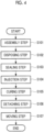
- Fig. 4 is a flowchart showing the composite material molding method according to the present embodiment.
- step S101 assembly step
- assembly is performed so that the third fiber preform FB3 is sandwiched between the core portion 11 and the core portion 12, and the second fiber preform FB2 is in a state of being in contact with the core portion 11 and the core portion 12.
- step S102 the core portion 11 and the core portion 12 assembled in step S101 are disposed in the recessed portion 21 of the first curing mold 20 together with the second fiber preform FB2 and the third fiber preform FB3.
- the first fiber preform FB1 is disposed on the first curing mold 20 so as to be in contact with the molding surface 20a and the molding surface 20b of the first curing mold 20.
- the second curing mold 25 is disposed so that the molding surface 25a and the molding surface 25b come into contact with the first fiber preform FB1.
- step S103 the fiber preform FB is sealed in the first curing mold 20 and the second curing mold 25 to form the sealed space CS.
- the bagging film 30 is joined to the first curing mold 20 by the sealant tape ST so as to cover an entire periphery of the first curing mold 20, so that the sealed space CS is formed.
- auxiliary materials such as a release film, a peel ply, and a breather may be disposed between the bagging film 30 and the fiber preform FB, as necessary.
- the formation of the sealed space CS by the bagging film 30 is an example.
- another curing mold (not shown) may be disposed above the first curing mold 20 so as to cover the fiber preform FB disposed on the first curing mold 20, and the sealed space CS may be formed by the first curing mold 20 and the other curing mold.
- step S103 when the sealed space CS is formed, the resin injection line 50 connected to the supply source 330 of the resin material RM and the sealed space CS enter a state of communicating with each other.
- the suction line 40 connected to the suction source 320 and the sealed space CS enter a state of communicating with each other.
- step S104 injection step
- the air in the sealed space CS formed in step S102 is suctioned such that the sealed space CS is depressurized and the resin material RM is injected into the fiber preform FB sealed in the sealed space CS.
- the suction source 320 is operated such that the air existing in the sealed space CS is discharged from the sealed space CS via the suction line 40 and the pressure of the sealed space CS is reduced to a vacuum state lower than the atmospheric pressure or a pressure close to the vacuum state.
- the supply source 330 is brought into a state where the resin material RM can be supplied to the resin injection line 50, and the resin material RM is injected into the sealed space CS by a pressure difference between the resin injection line 50 and the depressurized sealed space CS.
- the resin material RM injected into the sealed space CS infiltrates into the fiber preform FB when the resin material RM is guided from a region into which the resin material RM is injected from the resin injection line 50 to a region suctioned by the suction line 40.
- step S104 injection step
- the sealed space CS is depressurized to a vacuum state or a pressure close to the vacuum state
- the fiber preform FB and the infiltrating resin material RM are pressurized by the atmospheric pressure.
- step S105 the thermosetting resin material RM injected into the fiber preform FB in step S104 (injection step) is heated to a temperature equal to or higher than a thermosetting temperature by a heating unit (not shown) to cure the resin material RM.
- step S105 the resin material RM is cooled so that the resin material RM is sufficiently lower than a softening temperature.
- step S106 the composite material 200 including the resin material RM and the fiber preform FB cured in step S104 (curing step) is detached from the molding device 100. Specifically, the sealant tape ST that joins the bagging film 30 and the first curing mold 20 is removed, and the bagging film 30 is detached from the first curing mold 20.
- the second curing mold 25 is detached from the first curing mold 20 from which the bagging film 30 has been detached. Thereafter, the composite material 200 (a product in which the fiber preform FB is infiltrated by the resin material RM and is cured) in a state where the core portion 11 and the core portion 12 are attached is detached from the first curing mold 20.
- the composite material 200 a product in which the fiber preform FB is infiltrated by the resin material RM and is cured
- Fig. 5 is a perspective view showing a state in which the composite material 200 molded by the molding device 100 is detached from the first curing mold 20. As shown in Fig. 5 , the core portion 11 and the core portion 12 are in a state of being attached to the composite material 200.
- Fig. 6 is a perspective view showing a state in which the core portions 11 and 12 shown in Fig. 5 are moved by the moving mechanisms 61 and 62.
- step S107 moving step
- the molding surface 11a is separated by the moving mechanism 61 from the third fiber preform FB3 containing the resin material RM molded and cured by the molding surface 11a of the core portion 11.
- the molding surface 12a is separated by the moving mechanism 62 from the third fiber preform FB3 containing the resin material RM molded and cured by the molding surface 12a of the core portion 12.
- step S107 the moving mechanism 61 moves the core portion 11 along a predetermined direction PD in which groove portions (first groove portions) 11b formed on the molding surface 11a extend, while maintaining a state in which the molding surface 11a is in contact with the end surface FB3a of the third fiber preform FB3.
- the moving mechanism 62 moves the core portion 12 along the predetermined direction PD in which groove portions (first groove portions) 12b formed on the molding surface 12a extend, while maintaining a state in which the molding surface 12a is in contact with the end surface FB3b of the third fiber preform FB3.
- Fig. 7 is a view showing the molding surface 12a of the core portion 12 being in contact with the end surface FB3b of the third fiber preform FB3.
- Fig. 8 is a view showing a side surface 12c of the core portion 12 being in contact with a side surface FB3c of the second fiber preform FB2.
- Fig. 9 is a view showing a bottom surface 12d of the core portion 12 being in contact with an upper surface FB3d of the second fiber preform FB2.
- the groove portions 12b which extend in the predetermined direction PD on a plane parallel to the XZ plane and through which the resin material RM flows are formed.
- the groove portions 12b allow the resin material RM to flow such that the resin material RM is diffused into the end surface FB3b of the third fiber preform FB3 which is molded by the molding surface 12a.
- groove portions 12e which extend in a Z-axis direction on a plane parallel to the YZ plane and through which the resin material RM flows are formed.
- the groove portions 12e allow the resin material RM to flow such that the resin material RM is diffused into the side surface FB3c of the second fiber preform FB2 which is molded by the side surface 12c.
- groove portions 12f which extend in an X-axis direction on a plane parallel to the XY plane and through which the resin material RM flows are formed.
- the groove portions 12f allow the resin material RM to flow such that the resin material RM is diffused into the upper surface FB3d of the second fiber preform FB2 which is molded by the bottom surface 12d.
- a shape corresponding to the groove portions 12b formed on the molding surface 12a of the core portion 12 is formed on the end surface FB3b
- a shape corresponding to the groove portions 12e formed on the side surface 12c of the core portion 12 is formed on the side surface FB3c
- a shape corresponding to the groove portions 12f formed on the bottom surface 12d of the core portion 12 is formed on the upper surface FB3d.
- step S107 moving step
- the moving mechanism 62 moves the core portion 12 along the predetermined direction PD in which the groove portions (first groove portions) 12b formed on the molding surface 12a extend, while maintaining a state in which the molding surface 12a is in contact with the end surface FB3b of the third fiber preform FB3.
- the resin material RM cured along the shape of the groove portions 12b adheres to the end surface FB3b of the third fiber preform FB3 and enters a state of meshing with the groove portions 12b.
- the groove portions 12b do not interfere with the resin material RM having a protruding shape formed on the end surface FB3b of the third fiber preform FB3.
- Fig. 10 is a view showing the molding surface 11a of the core portion 11 being in contact with the end surface FB3a of the third fiber preform FB3.
- Fig. 8 is a view showing a side surface 11c of the core portion 11 being in contact with a side surface FB3e of the second fiber preform FB2.
- Fig. 9 is a view showing a bottom surface 11d of the core portion 11 being in contact with an upper surface FB3f of the second fiber preform FB2.
- the groove portions 11b which extend in the predetermined direction PD on a plane parallel to the XZ plane and through which the resin material RM flows are formed.
- the groove portions 11b allow the resin material RM to flow such that the resin material RM is diffused into the end surface FB3a of the third fiber preform FB3 which is molded by the molding surface 11a.
- groove portions 11e which extend in the Z-axis direction on a plane parallel to the YZ plane and through which the resin material RM flows are formed.
- the groove portions 11e allow the resin material RM to flow such that the resin material RM is diffused into the side surface FB3e of the second fiber preform FB2 which is molded by the side surface 11c.
- groove portions 11f which extend in the X-axis direction on a plane parallel to the XY plane and through which the resin material RM flows are formed.
- the groove portions 11f allow the resin material RM to flow such that the resin material RM is diffused into the upper surface FB3f of the second fiber preform FB2 which is molded by the bottom surface 11d.
- a shape corresponding to the groove portions 11b formed on the molding surface 11a of the core portion 11 is formed on the end surface FB3a, a shape corresponding to the groove portions 11e formed on the side surface 11c of the core portion 11 is formed on the side surface FB3e, and a shape corresponding to the groove portions 11f formed on the bottom surface 11d of the core portion 11 is formed on the upper surface FB3f.
- step S107 moving step
- the moving mechanism 61 moves the core portion 11 along the predetermined direction PD in which the groove portions (first groove portions) 11b formed on the molding surface 11a extend, while maintaining a state in which the molding surface 11a is in contact with the end surface FB3a of the third fiber preform FB3. This is because the resin material RM cured along the shape of the groove portions 11b adheres to the end surface FB3a of the third fiber preform FB3 and enters a state of meshing with the groove portions 11b.
- the groove portions 11b do not interfere with the resin material RM having a protruding shape formed on the end surface FB3a of the third fiber preform FB3.
- step S107 described above the moving mechanism 61 moves the core portion 11 and the moving mechanism 62 moves the core portion 12.
- another form may be used.
- an operator may hold the core portion 11 via a bare hand or a jig (not shown) and move the core portion 11 in the same manner as the moving mechanism 61.
- the operator may hold the core portion 12 via a bare hand or a jig (not shown) and move the core portion 12 in the same manner as the moving mechanism 62.
- core portions 11A and 12A of a modification example of the present embodiment and a moving step of moving the core portions 11A and 12A of the modification example will be described.
- the core portion 11A of the modification example is different from the core portion 11A described above in a shape of groove portions formed on a surface.
- Fig. 11 is a perspective view showing a state in which the core portions 11A and 12A are moved by the moving mechanisms 61 and 62.
- Fig. 12 is a view showing a molding surface 12Aa of the core portion 12A being in contact with the end surface FB3b of the third fiber preform FB3.
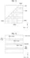
- Fig. 13 is a view showing a side surface 12Ac of the core portion 12A being in contact with the side surface FB3c of the second fiber preform FB2.
- Fig. 14 is a view showing a bottom surface 12Ad of the core portion 12A being in contact with the upper surface FB3d of the second fiber preform FB2.
- a plurality of groove portions 12Ab1 which extend along a Z-axis on a plane parallel to the XZ plane and through which the resin material RM flows, and a plurality of groove portions 12Ab2 which extend along an X-axis and through which the resin material RM flows are formed.
- the groove portions 12Ab1 and the groove portions 12Ab2 allow the resin material RM to flow such that the resin material RM is diffused into the end surface FB3b of the third fiber preform FB3 which is molded by the molding surface 12Aa.
- a plurality of groove portions 12Ae which extend along the predetermined direction PDb parallel to a Y-axis on a plane parallel to the YZ plane and through which the resin material RM flows are formed.
- the groove portions 12Ae allow the resin material RM to flow such that the resin material RM is diffused into the side surface FB3c of the second fiber preform FB2 which is molded by the side surface 12Ac.
- a plurality of groove portions 12Af which extend along the predetermined direction PDb parallel to the Y-axis on a plane parallel to the XY plane and through which the resin material RM flows are formed.
- the groove portions 12Af allow the resin material RM to flow such that the resin material RM is diffused into the upper surface FB3d of the second fiber preform FB2 which is molded by the bottom surface 12Ad.
- a shape corresponding to the groove portions 12Ab1 and 12Ab2 formed on the molding surface 12Aa of the core portion 12A is formed on the end surface FB3b
- a shape corresponding to the groove portions 12Ae formed on the side surface 12Ac of the core portion 12A is formed on the side surface FB3c
- a shape corresponding to the groove portions 12Af formed on the bottom surface 12Ad of the core portion 12A is formed on the upper surface FB3d.
- step S107 the moving mechanism 62 moves the core portion 12A along the predetermined direction PDb in which the groove portions (first groove portions) 12Ae formed on the side surface 12Ac extend, while maintaining a state in which the side surface 12Ac is in contact with the side surface FB3c of the third fiber preform FB3.
- the moving mechanism 62 moves the core portion 12A along the predetermined direction PDb in which the groove portions (first groove portions) 12Af formed on the bottom surface 12Ad extend, while maintaining a state in which the bottom surface 12Ad is in contact with the upper surface FB3d of the third fiber preform FB3.
- the core portion 12A is moved along the predetermined direction PDb because the resin material RM cured along the shapes of the groove portions 12Ae and the groove portions 12Af adheres to the side surface FB3c and the upper surface FB3d of the third fiber preform FB3 and enters a state of meshing with the groove portions 12Ae and the groove portions 12Af.
- the groove portions 12Ae do not interfere with the resin material RM having a protruding shape formed on the side surface FB3c of the third fiber preform FB3.
- the groove portions 12Af do not interfere with the resin material RM having a protruding shape formed on the upper surface FB3d of the third fiber preform FB3.
- Fig. 15 is a view showing a molding surface 11Aa of the core portion 11A being in contact with the end surface FB3a of the third fiber preform FB3.
- Fig. 13 is a view showing a side surface 11Ac of the core portion 11A being in contact with the side surface FB3e of the second fiber preform FB2.
- Fig. 14 is a view showing a bottom surface 11Ad of the core portion 11A being in contact with the upper surface FB3f of the second fiber preform FB2.
- a plurality of groove portions 11Ab1 which extend along the Z-axis on a plane parallel to the XZ plane and through which the resin material RM flows, and a plurality of groove portions 11Ab2 which extend along the X-axis and through which the resin material RM flows are formed.
- the groove portions 11Ab1 and the groove portions 11Ab2 allow the resin material RM to flow such that the resin material RM is diffused into the end surface FB3a of the third fiber preform FB3 which is molded by the molding surface 11Aa.
- a plurality of groove portions 11e which extend along the predetermined direction PDa parallel to the Y-axis on a plane parallel to the YZ plane and through which the resin material RM flows are formed.
- the groove portions 11Ae allow the resin material RM to flow such that the resin material RM is diffused into the side surface FB3e of the second fiber preform FB2 which is molded by the side surface 11Ac.
- a plurality of groove portions 11Af which extend along the predetermined direction PDa parallel to the Y-axis on a plane parallel to the XY plane and through which the resin material RM flows are formed.
- the groove portions 11Af allow the resin material RM to flow such that the resin material RM is diffused into the upper surface FB3f of the second fiber preform FB2 which is molded by the bottom surface 11Ad.
- a shape corresponding to the groove portions 11Ab1 and 11Ab2 formed on the molding surface 11Aa of the core portion 11A is formed on the end surface FB3a, and a shape corresponding to the groove portions 11Ae formed on the side surface 11Ac of the core portion 11A is formed on the side surface FB3e, and a shape corresponding to the groove portions 11Af formed on the bottom surface 11Ad of the core portion 11A is formed on the upper surface FB3f.
- step S107 moving step
- the moving mechanism 61 moves the core portion 11A along the predetermined direction PDa in which the groove portions (first groove portions) 11Ae formed on the side surface 11Ac extend, while maintaining a state in which the side surface 11Ac is in contact with the side surface FB3e of the third fiber preform FB3.
- the moving mechanism 61 moves the core portion 11A along the predetermined direction PDa in which the groove portions (first groove portions) 11Af formed on the bottom surface 11Ad extend, while maintaining a state in which the bottom surface 11Ad is in contact with the upper surface FB3f of the third fiber preform FB3.
- the core portion 11A is moved along the predetermined direction PDa because the resin material RM cured along the shapes of the groove portions 11Ae and the groove portions 11Af adheres to the side surface FB3e and the upper surface FB3f of the third fiber preform FB3 and enters a state of meshing with the groove portions 11Ae and the groove portions 11Af.
- the groove portions 11Ae do not interfere with the resin material RM having a protruding shape formed on the side surface FB3e of the third fiber preform FB3.
- the groove portions 11Af do not interfere with the resin material RM having a protruding shape formed on the upper surface FB3f of the third fiber preform FB3.
- Fig. 16 is a plan view of the recessed portion 21 of the first curing mold 20 as viewed from above, and shows a state in which the pair of core portions 11 and 12 are disposed.
- the plurality of groove portions 22a are formed on the molding surface 20a of the first curing mold 20.
- the resin material RM guided to the groove portions 22a disposed at a position corresponding to the recessed portion 21 is guided to the recessed portion 21 via the groove portions 22a.
- An upper surface (contact surface) 21a of the recessed portion 21 of the first curing mold 20 shown in Fig. 16 is a surface that comes into contact with the bottom surface 11d of the core portion 11 and the bottom surface 12d of the core portion 12.
- Groove portions (third groove portions) 21b through which the resin material RM flows between the recessed portion 21 and the core portions 11 and 12 are on the upper surface 21a.
- the core portion 11 has groove portions (second groove portions) 11g through which the resin material RM flows from the upper surface 21a of the recessed portion 21 toward the third fiber preform FB3.
- the core portion 12 has groove portions (second groove portions) 12g in which the resin material RM flows from the upper surface 21a of the recessed portion 21 toward the third fiber preform FB3.
- the core portion 11 is disposed in the recessed portion 21 so that end portions of the groove portions 11g on an upper surface 21a side communicate with the groove portions 21b.
- the core portion 12 is disposed in the recessed portion 21 so that end portions of the groove portions 12g on the upper surface 21a side communicate with the groove portions 21b.
- the groove portions 11g and the groove portions 12g form flow paths through which the resin material RM flows from the upper surface 21a of the recessed portion 21 toward the third fiber preform FB3. Through the flow paths, the resin material RM guided to the recessed portion 21 of the first curing mold 20 can be guided to the third fiber preform FB3 via the core portion 11 and the core portion 12.
- the groove portions 21b formed on the upper surface 21a of the recessed portion 21 are formed to extend toward a central portion of the recessed portion 21 in the longitudinal direction LD, but may have another form.
- the groove portions 21b may be formed as shown in Fig. 17 .
- Fig. 17 is a plan view of the recessed portion 21 of the first curing mold 20 of a modification example as viewed from above, and shows a state in which the pair of core portions 11 and 12 are disposed.
- the plurality of groove portions 21b formed on the upper surface 21a of the recessed portion 21 may be formed to extend in the same direction.
- at least any one of the plurality of groove portions 21b is disposed so as to communicate with the end portions of the groove portions 11g of the core portion 11 and the groove portions 12g of the core portion 12.
- the fiber preform FB is disposed on the molding surfaces 11a and 12a of the core portions 11 and 12 and the molding surfaces 20a and 20b of the first curing mold 20, the sealed space CS is formed by sealing the fiber preform FB on the first curing mold 20 in which the core portions 11 and 12 are accommodated in the recessed portion 21 of the first curing mold 20, with the bagging film 30, and the air in the sealed space CS is suctioned to depressurize the sealed space CS, so that the resin material RM is injected into the sealed space CS.
- the resin material RM injected into the sealed space CS infiltrates into the fiber preform FB when the resin material RM is guided from a region into which the resin material RM is injected from the resin injection line 50 to a region suctioned by the suction line 40.
- the groove portions 11b and 12b which extend in the predetermined direction PD and through which the resin material RM flows are formed.
- the resin material RM is reliably diffused into the surfaces of the fiber preform FB which is molded by the molding surfaces 11a and 12a of the core portions 11 and 12.
- the resin material RM cured along the shapes of the groove portions 11b and 12b adheres to the surfaces of the fiber preform FB and enters a state of meshing with the groove portions 11b and 12b.
- the moving mechanisms 61 and 62 move the core portions 11 and 12 along the predetermined direction PD in which the groove portions 11b and 12b extend, while maintaining a state in which the molding surfaces 11a and 12a are in contact with the fiber preform FB. Since the direction in which the core portions 11 and 12 move coincides with the predetermined direction PD in which the groove portions 11b and 12b extend, when the core portions 11 and 12 move, the groove portions 11b and 12b do not interfere with the resin material having a protruding shape formed on a surface of a product. Therefore, the core portions 11 and 12 can be moved without interfering with the product, and the resin material RM can be diffused in the surface direction of the fiber preform FB to infiltrate into the entire fiber preform FB.
- the end portions of the groove portions 11g and 12g on the upper surface 21a side through which the resin material RM flows from the upper surface 21a of the recessed portion 21 toward the fiber preform FB communicate with the groove portions 21b formed on the upper surface 21a. Therefore, the resin material RM flowing through the groove portions 21b can be reliably guided to the fiber preform FB via the groove portions 11g and 12g.
- the fiber-reinforced composite material molding device according to the embodiment described above is identified as follows, for example.
- the fiber-reinforced composite material molding device includes: a core portion (11, 12) having a first molding surface (11a, 12a) for molding a fiber preform (FB); a molding tool (20) having a second molding surface (20a, 20b) for molding the fiber preform and a recessed portion (21) that accommodates the core portion; a sealing member (30) that forms a sealed space (CS) by sealing the fiber preform in the molding tool in which the core portion is accommodated in the recessed portion; a suction portion (40) that suctions the air in the sealed space to depressurize the sealed space; a resin injection portion (50) that injects a resin material (RM) into the fiber preform which is sealed in the sealed space depressurized by the suction portion; and a moving mechanism (61, 62) that separates the first molding surface from the fiber preform including the resin material which is molded by the first molding surface and cured, in which a first groove portion (11b, 12b) which extends in a pre
- the fiber preform is disposed on the first molding surface of the core portion and the second molding surface of the molding tool, the sealed space is formed by sealing the fiber preform on the molding tool in which the core portion is accommodated in the recessed portion of the molding tool, with the sealing member, and the air in the sealed space is suctioned to depressurize the sealed space, so that the resin material is injected into the sealed space.
- the resin material injected into the sealed space infiltrates into the fiber preform when the resin material is guided from a region into which the resin material is injected from the resin injection portion to a region suctioned by the suction portion.
- the first groove portion which extends in the predetermined direction and through which the resin material flows is formed.
- the resin material is reliably diffused into a surface of the fiber preform which is molded by the first molding surface of the core portion.
- the resin material remaining in the groove portion is cured, the resin material cured along a shape of the groove portion adheres to the surface of the fiber preform and enters a state of meshing with the first groove portion.
- the moving mechanism moves the core portion along the predetermined direction in which the first groove portion extends, while maintaining a state in which the first molding surface is in contact with the fiber preform. Since the direction in which the core portion moves coincides with the predetermined direction in which the first groove portion extends, when the core portion moves, the first groove portion does not interfere with the resin material having a protruding shape formed on the surface of the product. Therefore, it is possible to provide the fiber-reinforced composite material molding device in which the core portion can be moved without interfering with the product, and the resin material can be diffused in the surface direction of the fiber preform to infiltrate into the entire fiber preform.
- the core portion has a second groove portion (11g, 12g) through which the resin material flows from a contact surface (21a) of the recessed portion toward the fiber preform
- the molding tool has a third groove portion (21b) which is formed on the contact surface and through which the resin material flows, and the core portion is disposed in the recessed portion so that an end portion of the second groove portion on a contact surface side communicates with the third groove portion.
- the end portion of the second groove portion, through which the resin material flows from the contact surface of the recessed portion toward the fiber preform, on the contact surface side communicates with the third groove portion formed on the contact surface, the resin material flowing through the third groove portion can be reliably guided to the fiber preform through the second groove portion.
- the fiber-reinforced composite material molding method described in the embodiment described above is identified as follows, for example.
- the fiber-reinforced composite material molding method includes: a disposing step (S102) of disposing a core portion having a first molding surface for molding a fiber preform in a recessed portion of a molding tool having a second molding surface for molding the fiber preform; a sealing step (S103) of forming a sealed space by sealing the fiber preform on the molding tool in which the core portion is accommodated in the recessed portion, with a sealing member; a resin injection step (S104) of suctioning the air in the sealed space to depressurize the sealed space and inject a resin material into the fiber preform sealed in the sealed space; and a moving step (S107) of separating the first molding surface from the fiber preform including the resin material which is molded by the first molding surface and cured, in which a first groove portion which extends in a predetermined direction and through which the resin material flows is formed on the first molding surface, and in the moving step, the core portion is moved along the predetermined direction in which the first groove portion extends, while
- the fiber preform is disposed on the first molding surface of the core portion and the second molding surface of the molding tool, the sealed space is formed by sealing the fiber preform on the molding tool in which the core portion is accommodated in the recessed portion of the molding tool, with the sealing member, and the air in the sealed space is suctioned to depressurize the sealed space, so that the resin material is injected into the sealed space.
- the resin material injected into the sealed space infiltrates into the fiber preform when the resin material is guided from a region into which the resin material is injected from the resin injection portion to a region suctioned by the suction portion.
- the first groove portion which extends in the predetermined direction and through which the resin material flows is formed.
- the resin material is reliably diffused into a surface of the fiber preform which is molded by the first molding surface of the core portion.
- the resin material remaining in the groove portion is cured, the resin material cured along a shape of the groove portion adheres to the surface of the fiber preform and enters a state of meshing with the first groove portion.
- the core portion in the moving step, is moved along the predetermined direction in which the first groove portion extends, while maintaining a state in which the first molding surface is in contact with the fiber preform. Since the direction in which the core portion moves coincides with the predetermined direction in which the first groove portion extends, when the core portion moves, the first groove portion does not interfere with the resin material having a protruding shape formed on the surface of the product. Therefore, it is possible to provide the fiber-reinforced composite material molding method in which the core portion can be moved without interfering with the product, and the resin material can be diffused in the surface direction of the fiber preform to infiltrate into the entire fiber preform.
- a configuration is preferable in which the core portion has a second groove portion through which the resin material flows from a contact surface of the recessed portion toward the fiber preform, the molding tool has a third groove portion which is formed on the contact surface and through which the resin material flows, and in the disposing step, the core portion is disposed in the recessed portion so that an end portion of the second groove portion on a contact surface side communicates with the third groove portion.
- the end portion of the second groove portion, through which the resin material flows from the contact surface of the recessed portion toward the fiber preform, on the contact surface side communicates with the third groove portion formed on the contact surface, the resin material flowing through the third groove portion can be reliably guided to the fiber preform through the second groove portion.
Landscapes
- Engineering & Computer Science (AREA)
- Mechanical Engineering (AREA)
- Chemical & Material Sciences (AREA)
- Composite Materials (AREA)
- Architecture (AREA)
- Civil Engineering (AREA)
- Structural Engineering (AREA)
- Moulds For Moulding Plastics Or The Like (AREA)
- Moulding By Coating Moulds (AREA)
- Casting Or Compression Moulding Of Plastics Or The Like (AREA)
Claims (4)
- Dispositif de moulage de matériau composite renforcé de fibres, comprenant :une partie centrale (11, 12) présentant une première surface de moulage (11a, 12a) pour mouler une préforme de fibre (FB) ;un outil de moulage (20) présentant une deuxième surface de moulage (20a) pour mouler la préforme de fibre et une partie évidée (21) qui reçoit la partie centrale ;un élément de scellement (30) qui forme un espace scellé en scellant la préforme de fibre sur l'outil de moulage dans lequel la partie centrale est reçue dans la partie évidée ;une partie d'aspiration (40) qui aspire de l'air à partir de l'espace scellé afin de dépressuriser l'espace scellé ;caractérisé en ce que le dispositif de moulage comprend :une partie d'injection de résine (50) qui injecte un matériau de résine dans la préforme de fibre qui est scellée dans l'espace scellé dépressurisé par la partie d'aspiration ; etun mécanisme de déplacement (61, 62) qui sépare la première surface de moulage de la préforme de fibre incluant le matériau de résine qui est moulé par la première surface de moulage et durci,dans lequel une première partie de rainure (11b, 12b) qui s'étend dans une direction prédéterminée et à travers laquelle le matériau de résine s'écoule est formée sur la première surface de moulage, (11a, 12a), etle mécanisme de déplacement déplace la partie centrale le long de la direction prédéterminée dans laquelle la première partie de la rainure (11b, 12b) s'étend, tout en maintenant un état dans lequel la première surface de moulage (11a, 11b) est en contact avec la préforme de fibre (FB).
- Dispositif de moulage de matériau composite renforcé de fibres selon la revendication 1,dans lequel la partie centrale présente une deuxième partie de rainure (11g, 12g) à travers laquelle la résine s'écoule à partir d'une surface de contact de la partie évidée (21) en direction de la préforme de fibre,l'outil de moulage présente une troisième partie de rainure (21b) qui est formée sur la surface de contact et à travers laquelle le matériau de résine s'écoule, etla partie centrale est disposée dans la partie évidée de telle sorte qu'une partie d'extrémité de la deuxième partie de rainure sur un côté de la surface de contact communique avec la troisième partie de rainure.
- Procédé de moulage de matériau composite renforcé de fibres, comprenant :une étape de disposition pour disposer une partie centrale (11, 12) présentant une première surface de moulage (11a, 12a) pour mouler une préforme de fibre (FB) dans une partie évidée (21) d'un outil de moulage (20) présentant une deuxième surface de moulage (20a) pour mouler la préforme de fibre ;une étape de scellement pour former un espace scellé en scellant la préforme de fibre sur l'outil de moulage dans lequel la partie centrale est reçue dans la partie évidée, avec un élément de scellement (30) ;une étape d'injection de résine pour aspirer de l'air à partir de l'espace scellé afin de dépressuriser l'espace scellé et pour injecter un matériau de résine dans la préforme de fibre scellée dans l'espace scellé ; etune étape de déplacement pour séparer la première surface de moulage de la préforme de fibre incluant le matériau de résine qui est moulé par la première surface de moulage et durci,dans lequel une première partie de rainure (11b, 12b) qui s'étend dans une direction prédéterminée et à travers laquelle le matériau de résine s'écoule est formée sur la première surface de moulage (11a), etlors de l'étape de déplacement, la partie centrale est déplacée le long de la direction prédéterminée dans laquelle la première partie de la rainure (11b, 12b) s'étend, tout en maintenant un état dans lequel la première surface de moulage (11a) est en contact avec la préforme de fibre (FB).
- Procédé de moulage de matériau composite renforcé de fibres selon la revendication 3,dans lequel la partie centrale comprend une deuxième partie de rainure (11g, 12g) à travers laquelle la résine s'écoule à partir d'une surface de contact de la partie évidée (21) en direction de la préforme de fibre,l'outil de moulage présente une troisième partie de rainure (21b) qui est formée sur la surface de contact et à travers laquelle la résine s'écoule, etlors de l'étape de disposition, la partie centrale est disposée dans la partie évidée de telle sorte qu'une partie extrémité de la deuxième partie de rainure sur un côté de la surface de contact communique avec la troisième partie de rainure.
Applications Claiming Priority (1)
| Application Number | Priority Date | Filing Date | Title |
|---|---|---|---|
| PCT/JP2020/046549 WO2022130459A1 (fr) | 2020-12-14 | 2020-12-14 | Dispositif de mise en forme de matériau composite renforcé de fibres et procédé de mise en forme de matériau composite renforcé de fibres |
Publications (3)
| Publication Number | Publication Date |
|---|---|
| EP4169701A1 EP4169701A1 (fr) | 2023-04-26 |
| EP4169701A4 EP4169701A4 (fr) | 2023-08-09 |
| EP4169701B1 true EP4169701B1 (fr) | 2024-05-15 |
Family
ID=82057404
Family Applications (1)
| Application Number | Title | Priority Date | Filing Date |
|---|---|---|---|
| EP20965847.5A Active EP4169701B1 (fr) | 2020-12-14 | 2020-12-14 | Dispositif de mise en forme de matériau composite renforcé de fibres et procédé de mise en forme de matériau composite renforcé de fibres |
Country Status (4)
| Country | Link |
|---|---|
| US (1) | US12427731B2 (fr) |
| EP (1) | EP4169701B1 (fr) |
| JP (1) | JP7375227B2 (fr) |
| WO (1) | WO2022130459A1 (fr) |
Family Cites Families (6)
| Publication number | Priority date | Publication date | Assignee | Title |
|---|---|---|---|---|
| JP2571276Y2 (ja) * | 1991-09-30 | 1998-05-18 | いすゞ自動車株式会社 | 繊維強化樹脂成形用コア材 |
| US5958325A (en) | 1995-06-07 | 1999-09-28 | Tpi Technology, Inc. | Large composite structures and a method for production of large composite structures incorporating a resin distribution network |
| JPH11254566A (ja) | 1998-01-06 | 1999-09-21 | Toray Ind Inc | Frp構造体およびその製造方法 |
| JP2000043173A (ja) | 1998-07-31 | 2000-02-15 | Toray Ind Inc | コア材とそれを用いたfrp構造体およびその製造方法 |
| WO2017068497A1 (fr) * | 2015-10-19 | 2017-04-27 | Bombardier Inc. | Procédé et appareil pour former un ensemble composite peau-raidisseur |
| JP6728856B2 (ja) | 2016-03-25 | 2020-07-22 | 東レ株式会社 | Rtm製造装置および繊維強化プラスチックのrtm製造方法 |
-
2020
- 2020-12-14 WO PCT/JP2020/046549 patent/WO2022130459A1/fr not_active Ceased
- 2020-12-14 EP EP20965847.5A patent/EP4169701B1/fr active Active
- 2020-12-14 JP JP2022569334A patent/JP7375227B2/ja active Active
- 2020-12-14 US US18/016,551 patent/US12427731B2/en active Active
Also Published As
| Publication number | Publication date |
|---|---|
| EP4169701A4 (fr) | 2023-08-09 |
| US12427731B2 (en) | 2025-09-30 |
| WO2022130459A1 (fr) | 2022-06-23 |
| US20230278298A1 (en) | 2023-09-07 |
| JP7375227B2 (ja) | 2023-11-07 |
| EP4169701A1 (fr) | 2023-04-26 |
| JPWO2022130459A1 (fr) | 2022-06-23 |
Similar Documents
| Publication | Publication Date | Title |
|---|---|---|
| CA2987004C (fr) | Dispositif et procede de fabrication d'un article moule en matiere plastique renforce par fibres | |
| CA2770383C (fr) | Procede et dispositif pour fabriquer un element poutre | |
| KR101837217B1 (ko) | 일체화된 보강부재를 갖는 복합 구조물 그 제조 방법 | |
| KR101930112B1 (ko) | 복합재 스티프너를 이송하고 배치하여 밀착하기 위한 방법 및 장치 | |
| US11701797B2 (en) | Composite material molding jig and composite material molding method | |
| CN105899350B (zh) | 用于由纤维增强复合材料连续地制造组件的设备和方法以及模具组 | |
| JP5476916B2 (ja) | 繊維強化プラスチックの製造方法 | |
| US20230294371A1 (en) | Composite material molding method | |
| EP3072661A1 (fr) | Gabarit de moulage frp et procédé de moulage d'une structure frp | |
| CN108136696A (zh) | 形成复合表层加强件组件的方法和设备 | |
| CN105705320A (zh) | 用于生产复合材料部件的设备及方法 | |
| US12427731B2 (en) | Fiber-reinforced composite material shaping device and fiber-reinforced composite material shaping method | |
| EP4059688B1 (fr) | Procédé de mise en forme de composite renforcé par des fibres et appareil de formation de composite renforcé par des fibres | |
| JP7225474B2 (ja) | 繊維強化複合材成形装置および繊維強化複合材成形方法 | |
| KR20170133769A (ko) | Rtm 성형 방법 및 장치 | |
| KR20170123893A (ko) | 양방향 z-피닝 패치 및 그의 제조방법 | |
| CN114516181A (zh) | 复合材料零件的连续流水线制造 | |
| US20140150969A1 (en) | Device for the manufacture of a bonded component and also a method | |
| EP2873516A1 (fr) | Procédé et dispositif de fabrication d'un composant de matériau composite | |
| EP4063107B1 (fr) | Procédé de moulage de matériau composite renforcé par des fibres, et système comprenant un appareil de moulage de matériau composite renforcé par des fibres et un matériau de base en fibres. | |
| CA3061458C (fr) | Procede de moulage de materiau composite et dispositif de moulage de materiau composite | |
| EP4563334A1 (fr) | Procédé de moulage et dispositif de moulage d'un matériau composite | |
| EP4079485B1 (fr) | Procédé de façonnage et système | |
| KR20180055554A (ko) | Rtm 성형 장치 및 방법 |
Legal Events
| Date | Code | Title | Description |
|---|---|---|---|
| STAA | Information on the status of an ep patent application or granted ep patent |
Free format text: STATUS: THE INTERNATIONAL PUBLICATION HAS BEEN MADE |
|
| PUAI | Public reference made under article 153(3) epc to a published international application that has entered the european phase |
Free format text: ORIGINAL CODE: 0009012 |
|
| STAA | Information on the status of an ep patent application or granted ep patent |
Free format text: STATUS: REQUEST FOR EXAMINATION WAS MADE |
|
| 17P | Request for examination filed |
Effective date: 20230119 |
|
| AK | Designated contracting states |
Kind code of ref document: A1 Designated state(s): AL AT BE BG CH CY CZ DE DK EE ES FI FR GB GR HR HU IE IS IT LI LT LU LV MC MK MT NL NO PL PT RO RS SE SI SK SM TR |
|
| A4 | Supplementary search report drawn up and despatched |
Effective date: 20230712 |
|
| RIC1 | Information provided on ipc code assigned before grant |
Ipc: B29C 33/30 20060101ALI20230706BHEP Ipc: B29D 99/00 20100101ALI20230706BHEP Ipc: B29C 70/54 20060101ALI20230706BHEP Ipc: B29C 33/44 20060101ALI20230706BHEP Ipc: B29C 70/44 20060101ALI20230706BHEP Ipc: B29C 70/46 20060101AFI20230706BHEP |
|
| GRAP | Despatch of communication of intention to grant a patent |
Free format text: ORIGINAL CODE: EPIDOSNIGR1 |
|
| STAA | Information on the status of an ep patent application or granted ep patent |
Free format text: STATUS: GRANT OF PATENT IS INTENDED |
|
| DAV | Request for validation of the european patent (deleted) | ||
| DAX | Request for extension of the european patent (deleted) | ||
| INTG | Intention to grant announced |
Effective date: 20231208 |
|
| GRAS | Grant fee paid |
Free format text: ORIGINAL CODE: EPIDOSNIGR3 |
|
| GRAA | (expected) grant |
Free format text: ORIGINAL CODE: 0009210 |
|
| STAA | Information on the status of an ep patent application or granted ep patent |
Free format text: STATUS: THE PATENT HAS BEEN GRANTED |
|
| AK | Designated contracting states |
Kind code of ref document: B1 Designated state(s): AL AT BE BG CH CY CZ DE DK EE ES FI FR GB GR HR HU IE IS IT LI LT LU LV MC MK MT NL NO PL PT RO RS SE SI SK SM TR |
|
| REG | Reference to a national code |
Ref country code: CH Ref legal event code: EP |
|
| REG | Reference to a national code |
Ref country code: IE Ref legal event code: FG4D |
|
| REG | Reference to a national code |
Ref country code: DE Ref legal event code: R096 Ref document number: 602020031135 Country of ref document: DE |
|
| REG | Reference to a national code |
Ref country code: LT Ref legal event code: MG9D |
|
| REG | Reference to a national code |
Ref country code: NL Ref legal event code: MP Effective date: 20240515 |
|
| PG25 | Lapsed in a contracting state [announced via postgrant information from national office to epo] |
Ref country code: IS Free format text: LAPSE BECAUSE OF FAILURE TO SUBMIT A TRANSLATION OF THE DESCRIPTION OR TO PAY THE FEE WITHIN THE PRESCRIBED TIME-LIMIT Effective date: 20240915 |
|
| PG25 | Lapsed in a contracting state [announced via postgrant information from national office to epo] |
Ref country code: BG Free format text: LAPSE BECAUSE OF FAILURE TO SUBMIT A TRANSLATION OF THE DESCRIPTION OR TO PAY THE FEE WITHIN THE PRESCRIBED TIME-LIMIT Effective date: 20240515 |
|
| PG25 | Lapsed in a contracting state [announced via postgrant information from national office to epo] |
Ref country code: FI Free format text: LAPSE BECAUSE OF FAILURE TO SUBMIT A TRANSLATION OF THE DESCRIPTION OR TO PAY THE FEE WITHIN THE PRESCRIBED TIME-LIMIT Effective date: 20240515 Ref country code: HR Free format text: LAPSE BECAUSE OF FAILURE TO SUBMIT A TRANSLATION OF THE DESCRIPTION OR TO PAY THE FEE WITHIN THE PRESCRIBED TIME-LIMIT Effective date: 20240515 |
|
| PG25 | Lapsed in a contracting state [announced via postgrant information from national office to epo] |
Ref country code: GR Free format text: LAPSE BECAUSE OF FAILURE TO SUBMIT A TRANSLATION OF THE DESCRIPTION OR TO PAY THE FEE WITHIN THE PRESCRIBED TIME-LIMIT Effective date: 20240816 |
|
| PG25 | Lapsed in a contracting state [announced via postgrant information from national office to epo] |
Ref country code: PT Free format text: LAPSE BECAUSE OF FAILURE TO SUBMIT A TRANSLATION OF THE DESCRIPTION OR TO PAY THE FEE WITHIN THE PRESCRIBED TIME-LIMIT Effective date: 20240916 |
|
| REG | Reference to a national code |
Ref country code: AT Ref legal event code: MK05 Ref document number: 1686620 Country of ref document: AT Kind code of ref document: T Effective date: 20240515 |
|
| PG25 | Lapsed in a contracting state [announced via postgrant information from national office to epo] |
Ref country code: NL Free format text: LAPSE BECAUSE OF FAILURE TO SUBMIT A TRANSLATION OF THE DESCRIPTION OR TO PAY THE FEE WITHIN THE PRESCRIBED TIME-LIMIT Effective date: 20240515 |
|
| PG25 | Lapsed in a contracting state [announced via postgrant information from national office to epo] |
Ref country code: ES Free format text: LAPSE BECAUSE OF FAILURE TO SUBMIT A TRANSLATION OF THE DESCRIPTION OR TO PAY THE FEE WITHIN THE PRESCRIBED TIME-LIMIT Effective date: 20240515 |
|
| PG25 | Lapsed in a contracting state [announced via postgrant information from national office to epo] |
Ref country code: AT Free format text: LAPSE BECAUSE OF FAILURE TO SUBMIT A TRANSLATION OF THE DESCRIPTION OR TO PAY THE FEE WITHIN THE PRESCRIBED TIME-LIMIT Effective date: 20240515 |
|
| PG25 | Lapsed in a contracting state [announced via postgrant information from national office to epo] |
Ref country code: PL Free format text: LAPSE BECAUSE OF FAILURE TO SUBMIT A TRANSLATION OF THE DESCRIPTION OR TO PAY THE FEE WITHIN THE PRESCRIBED TIME-LIMIT Effective date: 20240515 |
|
| PG25 | Lapsed in a contracting state [announced via postgrant information from national office to epo] |
Ref country code: LV Free format text: LAPSE BECAUSE OF FAILURE TO SUBMIT A TRANSLATION OF THE DESCRIPTION OR TO PAY THE FEE WITHIN THE PRESCRIBED TIME-LIMIT Effective date: 20240515 |
|
| PG25 | Lapsed in a contracting state [announced via postgrant information from national office to epo] |
Ref country code: PT Free format text: LAPSE BECAUSE OF FAILURE TO SUBMIT A TRANSLATION OF THE DESCRIPTION OR TO PAY THE FEE WITHIN THE PRESCRIBED TIME-LIMIT Effective date: 20240916 Ref country code: PL Free format text: LAPSE BECAUSE OF FAILURE TO SUBMIT A TRANSLATION OF THE DESCRIPTION OR TO PAY THE FEE WITHIN THE PRESCRIBED TIME-LIMIT Effective date: 20240515 Ref country code: NO Free format text: LAPSE BECAUSE OF FAILURE TO SUBMIT A TRANSLATION OF THE DESCRIPTION OR TO PAY THE FEE WITHIN THE PRESCRIBED TIME-LIMIT Effective date: 20240815 Ref country code: NL Free format text: LAPSE BECAUSE OF FAILURE TO SUBMIT A TRANSLATION OF THE DESCRIPTION OR TO PAY THE FEE WITHIN THE PRESCRIBED TIME-LIMIT Effective date: 20240515 Ref country code: LV Free format text: LAPSE BECAUSE OF FAILURE TO SUBMIT A TRANSLATION OF THE DESCRIPTION OR TO PAY THE FEE WITHIN THE PRESCRIBED TIME-LIMIT Effective date: 20240515 Ref country code: IS Free format text: LAPSE BECAUSE OF FAILURE TO SUBMIT A TRANSLATION OF THE DESCRIPTION OR TO PAY THE FEE WITHIN THE PRESCRIBED TIME-LIMIT Effective date: 20240915 Ref country code: HR Free format text: LAPSE BECAUSE OF FAILURE TO SUBMIT A TRANSLATION OF THE DESCRIPTION OR TO PAY THE FEE WITHIN THE PRESCRIBED TIME-LIMIT Effective date: 20240515 Ref country code: GR Free format text: LAPSE BECAUSE OF FAILURE TO SUBMIT A TRANSLATION OF THE DESCRIPTION OR TO PAY THE FEE WITHIN THE PRESCRIBED TIME-LIMIT Effective date: 20240816 Ref country code: FI Free format text: LAPSE BECAUSE OF FAILURE TO SUBMIT A TRANSLATION OF THE DESCRIPTION OR TO PAY THE FEE WITHIN THE PRESCRIBED TIME-LIMIT Effective date: 20240515 Ref country code: ES Free format text: LAPSE BECAUSE OF FAILURE TO SUBMIT A TRANSLATION OF THE DESCRIPTION OR TO PAY THE FEE WITHIN THE PRESCRIBED TIME-LIMIT Effective date: 20240515 Ref country code: BG Free format text: LAPSE BECAUSE OF FAILURE TO SUBMIT A TRANSLATION OF THE DESCRIPTION OR TO PAY THE FEE WITHIN THE PRESCRIBED TIME-LIMIT Effective date: 20240515 Ref country code: AT Free format text: LAPSE BECAUSE OF FAILURE TO SUBMIT A TRANSLATION OF THE DESCRIPTION OR TO PAY THE FEE WITHIN THE PRESCRIBED TIME-LIMIT Effective date: 20240515 Ref country code: RS Free format text: LAPSE BECAUSE OF FAILURE TO SUBMIT A TRANSLATION OF THE DESCRIPTION OR TO PAY THE FEE WITHIN THE PRESCRIBED TIME-LIMIT Effective date: 20240815 |
|
| PG25 | Lapsed in a contracting state [announced via postgrant information from national office to epo] |
Ref country code: DK Free format text: LAPSE BECAUSE OF FAILURE TO SUBMIT A TRANSLATION OF THE DESCRIPTION OR TO PAY THE FEE WITHIN THE PRESCRIBED TIME-LIMIT Effective date: 20240515 |
|
| PG25 | Lapsed in a contracting state [announced via postgrant information from national office to epo] |
Ref country code: EE Free format text: LAPSE BECAUSE OF FAILURE TO SUBMIT A TRANSLATION OF THE DESCRIPTION OR TO PAY THE FEE WITHIN THE PRESCRIBED TIME-LIMIT Effective date: 20240515 |
|
| PG25 | Lapsed in a contracting state [announced via postgrant information from national office to epo] |
Ref country code: CZ Free format text: LAPSE BECAUSE OF FAILURE TO SUBMIT A TRANSLATION OF THE DESCRIPTION OR TO PAY THE FEE WITHIN THE PRESCRIBED TIME-LIMIT Effective date: 20240515 |
|
| PG25 | Lapsed in a contracting state [announced via postgrant information from national office to epo] |
Ref country code: SK Free format text: LAPSE BECAUSE OF FAILURE TO SUBMIT A TRANSLATION OF THE DESCRIPTION OR TO PAY THE FEE WITHIN THE PRESCRIBED TIME-LIMIT Effective date: 20240515 Ref country code: RO Free format text: LAPSE BECAUSE OF FAILURE TO SUBMIT A TRANSLATION OF THE DESCRIPTION OR TO PAY THE FEE WITHIN THE PRESCRIBED TIME-LIMIT Effective date: 20240515 |
|
| PG25 | Lapsed in a contracting state [announced via postgrant information from national office to epo] |
Ref country code: SM Free format text: LAPSE BECAUSE OF FAILURE TO SUBMIT A TRANSLATION OF THE DESCRIPTION OR TO PAY THE FEE WITHIN THE PRESCRIBED TIME-LIMIT Effective date: 20240515 |
|
| PG25 | Lapsed in a contracting state [announced via postgrant information from national office to epo] |
Ref country code: SM Free format text: LAPSE BECAUSE OF FAILURE TO SUBMIT A TRANSLATION OF THE DESCRIPTION OR TO PAY THE FEE WITHIN THE PRESCRIBED TIME-LIMIT Effective date: 20240515 Ref country code: SK Free format text: LAPSE BECAUSE OF FAILURE TO SUBMIT A TRANSLATION OF THE DESCRIPTION OR TO PAY THE FEE WITHIN THE PRESCRIBED TIME-LIMIT Effective date: 20240515 Ref country code: RO Free format text: LAPSE BECAUSE OF FAILURE TO SUBMIT A TRANSLATION OF THE DESCRIPTION OR TO PAY THE FEE WITHIN THE PRESCRIBED TIME-LIMIT Effective date: 20240515 Ref country code: EE Free format text: LAPSE BECAUSE OF FAILURE TO SUBMIT A TRANSLATION OF THE DESCRIPTION OR TO PAY THE FEE WITHIN THE PRESCRIBED TIME-LIMIT Effective date: 20240515 Ref country code: DK Free format text: LAPSE BECAUSE OF FAILURE TO SUBMIT A TRANSLATION OF THE DESCRIPTION OR TO PAY THE FEE WITHIN THE PRESCRIBED TIME-LIMIT Effective date: 20240515 Ref country code: CZ Free format text: LAPSE BECAUSE OF FAILURE TO SUBMIT A TRANSLATION OF THE DESCRIPTION OR TO PAY THE FEE WITHIN THE PRESCRIBED TIME-LIMIT Effective date: 20240515 |
|
| PG25 | Lapsed in a contracting state [announced via postgrant information from national office to epo] |
Ref country code: IT Free format text: LAPSE BECAUSE OF FAILURE TO SUBMIT A TRANSLATION OF THE DESCRIPTION OR TO PAY THE FEE WITHIN THE PRESCRIBED TIME-LIMIT Effective date: 20240515 |
|
| REG | Reference to a national code |
Ref country code: DE Ref legal event code: R097 Ref document number: 602020031135 Country of ref document: DE |
|
| PLBE | No opposition filed within time limit |
Free format text: ORIGINAL CODE: 0009261 |
|
| STAA | Information on the status of an ep patent application or granted ep patent |
Free format text: STATUS: NO OPPOSITION FILED WITHIN TIME LIMIT |
|
| 26N | No opposition filed |
Effective date: 20250218 |
|
| PG25 | Lapsed in a contracting state [announced via postgrant information from national office to epo] |
Ref country code: SI Free format text: LAPSE BECAUSE OF FAILURE TO SUBMIT A TRANSLATION OF THE DESCRIPTION OR TO PAY THE FEE WITHIN THE PRESCRIBED TIME-LIMIT Effective date: 20240515 |
|
| PG25 | Lapsed in a contracting state [announced via postgrant information from national office to epo] |
Ref country code: MC Free format text: LAPSE BECAUSE OF FAILURE TO SUBMIT A TRANSLATION OF THE DESCRIPTION OR TO PAY THE FEE WITHIN THE PRESCRIBED TIME-LIMIT Effective date: 20240515 |
|
| REG | Reference to a national code |
Ref country code: CH Ref legal event code: PL |
|
| PG25 | Lapsed in a contracting state [announced via postgrant information from national office to epo] |
Ref country code: LU Free format text: LAPSE BECAUSE OF NON-PAYMENT OF DUE FEES Effective date: 20241214 |
|
| GBPC | Gb: european patent ceased through non-payment of renewal fee |
Effective date: 20241214 |
|
| PG25 | Lapsed in a contracting state [announced via postgrant information from national office to epo] |
Ref country code: SE Free format text: LAPSE BECAUSE OF FAILURE TO SUBMIT A TRANSLATION OF THE DESCRIPTION OR TO PAY THE FEE WITHIN THE PRESCRIBED TIME-LIMIT Effective date: 20240515 |
|
| REG | Reference to a national code |
Ref country code: BE Ref legal event code: MM Effective date: 20241231 |
|
| PG25 | Lapsed in a contracting state [announced via postgrant information from national office to epo] |
Ref country code: BE Free format text: LAPSE BECAUSE OF NON-PAYMENT OF DUE FEES Effective date: 20241231 Ref country code: GB Free format text: LAPSE BECAUSE OF NON-PAYMENT OF DUE FEES Effective date: 20241214 |
|
| PG25 | Lapsed in a contracting state [announced via postgrant information from national office to epo] |
Ref country code: CH Free format text: LAPSE BECAUSE OF NON-PAYMENT OF DUE FEES Effective date: 20241231 |
|
| PG25 | Lapsed in a contracting state [announced via postgrant information from national office to epo] |
Ref country code: IE Free format text: LAPSE BECAUSE OF NON-PAYMENT OF DUE FEES Effective date: 20241214 |
|
| PGFP | Annual fee paid to national office [announced via postgrant information from national office to epo] |
Ref country code: DE Payment date: 20251028 Year of fee payment: 6 |
|
| PGFP | Annual fee paid to national office [announced via postgrant information from national office to epo] |
Ref country code: FR Payment date: 20251110 Year of fee payment: 6 |